Loading ...
Loading ...
Loading ...
07-02284A 4 LBG Distribution
AT THE END OF THE JOB
To reduce the possibility of drips when moving the unit, follow
these additional steps to ensure that all water is removed from the
unit.
NOTICE: To ensure all water is removed from the dehumidifier, the
unit will complete the defrost cycle even if the unit is turned off. If
the unit is unplugged during the defrost cycle, excessive water may
accumulate in the unit and may drip out when you move the unit.
NOTICE: To ensure the condensate tank empties completely while
purging, make sure the unit is placed upright on a horizontal surface.
1. If the unit is in a defrost cycle, wait until the unit has returned
to normal operating mode before proceeding. To check, review
the control panel. The control panel will show one of the
following:
Defrost in progress:
UNIT ON 00 HRS
DEFROST XX
Display mode when unit is in defrost mode. XX indicates the seconds
remaining on the defrost cycle.
Shutdown sequence
WAIT FOR
DEFROST XX
Display mode when unit in defrost and unit is powered down (shut off
by user). Unit will complete the defrost cycle to remove any built-up
ice then purge the pump. XX indicates the seconds remaining on the
defrost cycle.
Drying sequence
WAIT FOR
UNIT DRYING XX
Display mode when unit not in defrost and unit is powered down (shut
off by user). Unit will complete the 5 minute drying cycle then purge
the pump. XX indicates the seconds remaining on the drying cycle.
Normal display:
UNIT ON 00 HRS
INLET XX° C
Wait until the control shows the normal display before proceeding.
2. Gently rock the machine to ensure any water remaining on
interior surfaces falls into the pump area.
3. Press the PURGE key. When the purge cycle is complete, turn
the unit off.
4. Remove the external drain hose, drain it carefully, and secure
it by wrapping around the rear cord wrap.
5. Remove the power cord then wrap it around the Cord Wrap (see
Fig. A).
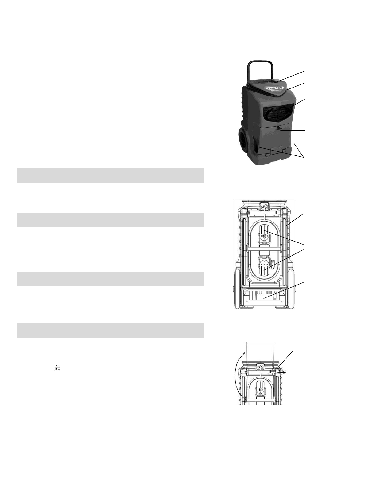
Fig. A: Parts Identification
BACK
Handle (in stored
position).
Hose storage tabs.
Rotate upper tab
180° to release/
secure hose.
Location of pump
and catch basin.
1. Rotate locking lever to
right to release handle.
2. Raise handle to upright
position and secure in
place with locking lever.
3. Reverse procedure to
secure handle for shipping
and storage.
SECURING HANDLE
Cord storage.
Air filter access
door. Lift handle
to release.
Air outlet. May be used
with standard 12 in.
rigid or layflat ducting.
Humid air inlet (both
sides of door).
Control panel
FRONT
Loading ...
Loading ...
Loading ...