
Loading ...
Loading ...
3
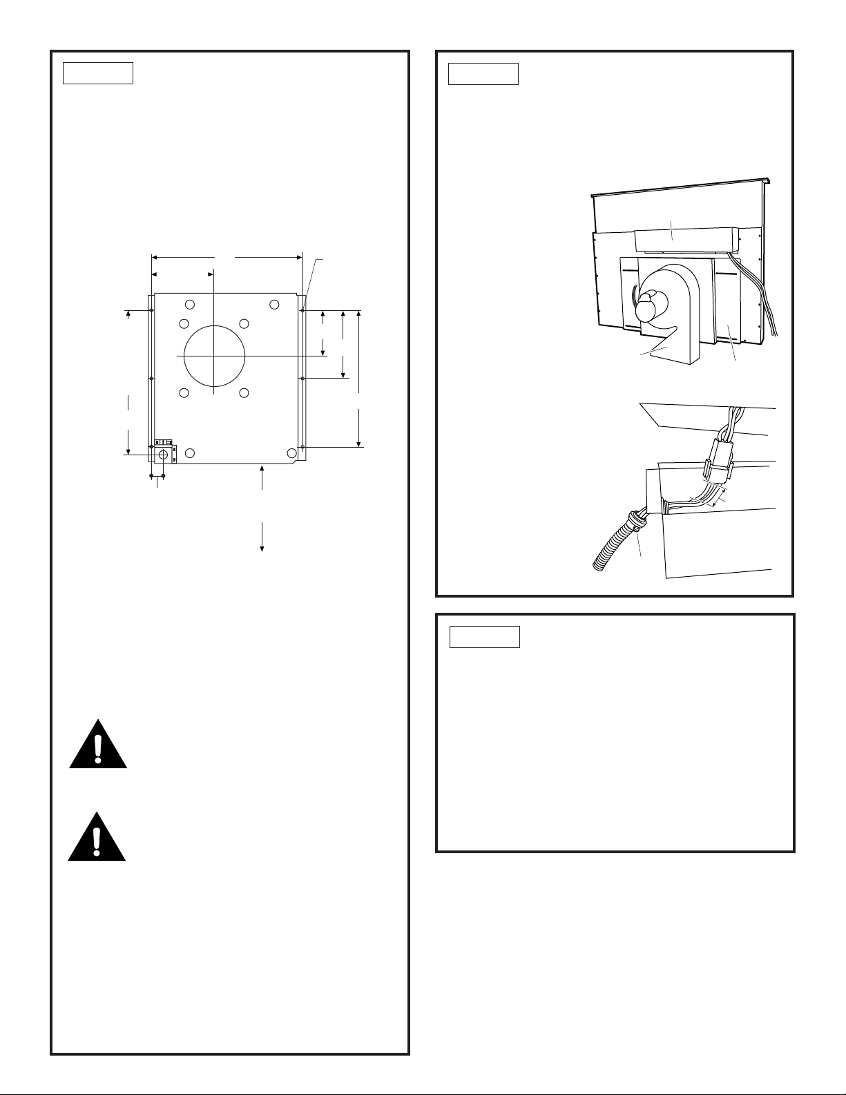
STEP 2 MARK MOUNTING
LOCATION
• The base is designed to be mounted to studs 16” on
center or to other suitable exterior surfaces. Use the
dimensions shown to determine the location of the
ducting and wiring through the wall.
OR
• Place the base against the exterior wall and mark
the 6 mounting locations, the 6” duct location and
the hole for the wiring. Use pencil or chalk.
• The bottom of the base assembly must be 10” Min.
above the ground. There should be no obstructions
to the discharge from the damper.
• Cut a 6-1/8” Dia. hole in the vertical structure to
accommodate a 6” round duct. Cut another hole for
the wiring.
• Drill 6 pilot holes through the wall for the 5/16”
fasteners (not supplied). Use fasteners appropriate
for the type of construction.
CAUTION
When cutting or drilling into a wall or ceiling, do not
damage electrical wiring or hidden utilities.
PRUDENCE
Lors de la coupe ou du perçage dans un mur ou un
plafond, il faut prendre soin de ne pas endommager
les fils électriques et autres services cachés.
• Check for interference with floor joists and stud
walls. If necessary, locate the base to provide a
secure installation.
• Place a 6” round duct through the hole extending
approximately 3” from the wall to provide a proper
seal with the blower. Secure the duct to the building
structure to prevent it from being pushed back when
the blower is installed.
STEP 3 PREPARE THE VENT
• Flatten the shipping box to use as a pad.
• Place the unit on its back and onto the protective
pad.
• Remove the 3 screws holding the control box on the
plenum. Retain screws.
• Cut the blower
leads approxi-
mately 3” from the
plug on the end of
the vent.
• Remove the blower
conduit by loosen-
ing the screw on
the fitting.
Blower/
Motor
Control Box
Mounting
Plate
STEP 4 REMOVE THE BLOWER
• Remove the 4 screws holding the blower to the
mounting plate. Retain all screws.
• Lift the blower off the assembly, turn it over to
access the 4 nuts holding the blower to the mounting
plate. Remove the nuts, lift the mounting plate off the
blower.
• Reinstall the mounting plate onto the plenum with
the 4 original screws.
IMPORTANT: Do not lift motor by power cable.
Damage will occur!
Control Box
Loosen
Screw
3"
10" Min
Above Ground
6-11/16"
16"
5-1/8"
6"
12"
Align
With Duct
Opening
On Outside
Wall
1-13/16"
12-15/16"
6 Holes
For 5/16"
Fastners
6-1/8" Dia.
Loading ...
Loading ...
Loading ...