INTRODUCTION
The VC60RIM and VC60SIM are impedance-multiplying stereo volume
controls that feature 12 control positions, soft-touch action and silent
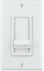
switching capability. The VC60RIM incorporates a rotary control; the
VC60SIM incorporates a slider control. Both volume controls can be safely
used with amplifiers that deliver up to 60 watts RMS per channel.
When properly implemented, Sonance VC60RIM and VC60SIM allow the
safe use of multiple pairs of speakers with amplifiers not specifically-designed
to run the low-impedance loads presented by multiple speakers. Adjustable
impedance jumpers allow as many as 8 pairs of 8-ohm speakers (or 4 pairs of
4-ohm speakers) to be driven by a single 8-ohm capable amplifier.
APPLICATIONS
The VC60RIM and VC60SIM are designed to have a single pair of speakers
connected to a single volume control. Their impedance-multiplying feature
allows multiple volume control/speaker sets to be safely used with a
single amplifier. The included adjustable impedance jumpers can be set to
accommodate different total numbers of speaker/volume control sets.
Important Note: These volume controls are intended for use primarily
in background music systems. The impedance jumpers increase the
impedance seen by the amplifier,
which reduces the amount of power
reaching each pair of speakers
, reducing the speaker’s overall output
capability. The more speakers being driven by a single amplifier
through VC60RIM/SIM controls, the higher the impedance jumpers
must be set and the lower the amount of power that will reach each
speaker. Operating multiple sets of speakers through VC60RIM/SIM
controls with jumpers set lower than recommended in order to increase
the system’s output capability can severely damage the amplifier.
If the system will include a pair of speakers intended for dedicated
higher-volume music listening, we strongly recommend that those
speakers be powered directly by a dedicated amplifier through a VC60R
or VC60S standard volume control.
CONNECTIONS
WARNING: Turn the amplifier’s power OFF until you have completed all of the
connections and have determined that they are correct. (If the amp’s AC plug is
accessible we recommend that you unplug it from the wall outlet to avoid acci-
dental turn-on and possible damage to the amplifier or speakers.)
The VC60RIM and VC60SIM have removable 4-pin screw connectors that
simplify connecting the speakers and amplifier.
1. Bring the wires from the speakers and amp through a backless J-box.
2. Insert the speaker wires as shown into the holes in the 4-pin screw connec-
tors. Make sure to insert the ‘+’ and ‘–’ leads into the correct holes
(see illustration, below).
Important: Make sure there are no
stray wires that can touch each
other. Touching wires can cause a
short-circuit that can damage the
amplifier.
Note: The connectors can accommo-
date wire as large as 14 gauge.
3. Using a small flat-blade screw-
driver, tighten the screws to
secure the wires in the connector.
4. Press the 4-pin screw connectors
into the corresponding speaker
terminals on the volume control until they lock into place.
IMPORTANT: Do not reverse the “Input” and “Output” connectors or the
volume control will not operate properly.
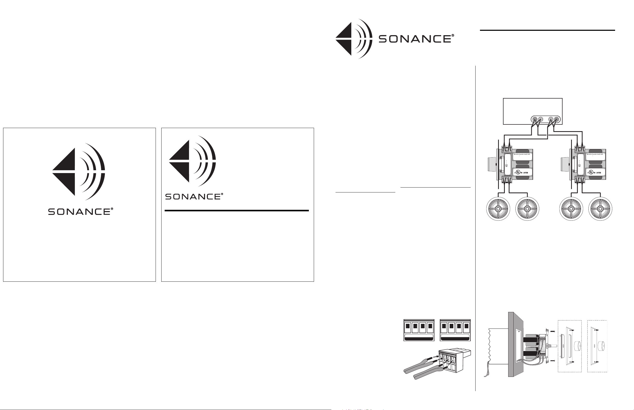
5.
CCoonnnneecctt oonnllyy 11 ppaaiirr ooff ssppeeaakkeerrss ttoo eeaacchh vvoolluummee ccoonnttrrooll..
Connect multiple
volume controls to the amplifier’s speaker terminals in parallel
(see illustration, below. VC60RIM shown).
MOUNTING
IMPORTANT: Do NOT install the volume control in the same electrical box as
AC house wiring, a light switch or any other high-voltage device or control. The
volume control can share gang boxes with other low-voltage controls such as
A/B speaker switches, infrared receivers, and line-level audio or video devices if
these other devices are rated as Class 2 devices according to the National
Electrical Code.
Use the included hardware to mount the volume control in a single or double
J-box as shown below. (Do not over-tighten the screws.) Attach your choice of
the included Decora® (VC60RIM/S) or standard (VC60RIM only) hardware.
Note: If you are installing the volume control into a typical plastic J-box you will
have to remove the J-box’s back panel to accommodate the control.
INSTRUCTION MANUAL
VC60RIM/VC60SIM
IMPEDANCE-MULTIPLYING
VOLUME CONTROLS
L+ L– R– R+
O U T P U T
R+ R– L– L+
INPUT
FROM AMPLIFIER T O SPEAKERS
VC60RIM VC60SIM
60W rms MAX Input/Ch
Tw o- 8 Ω Speakers
®
SPEAKERS
AMPLIFIER
R+ R– L– L+
O U T P U T
R+ R– L– L+
INPUT
Right
Speaker
Left
Speaker
Right
Speaker
Left
Speaker
VC60RIM VC60SIM
60W rms MAX Input/Ch
Tw o- 8 Ω Speakers
®
SPEAKERS
AMPLIFIER
R+ R– L– L+
O U T P U T
R+ R– L– L+
INPUT
VC60RIM
VC60RIM
VC60SIM
VC60SIM
L
+ –
R
– +
Amplifier/Receiver
SPEAKER OUTPUT
Sonance • 212 Avenida Fabricante • San Clemente, CA 92672-7531, USA
(800) 582-7777 or (949) 492-7777 • FAX: (949) 361-5151
Technical Support: (800) 582-0772
©2005 Dana Innovations, Inc. All rights reserved.
Sonance is a trademark of Dana Innovations, Inc.
Decora is a registered trademark of Leviton Manufacturing Co., Inc.
VC60RIM
VC60SIM
IMPEDANCE-MULTIPLYING
VOLUME CONTROLS
INSTRUCTION
MANUAL
1
Backless
J-Box
Decora
Hardware
Volume
Control
(VC60RIM
shown)
Standard
Hardware
www.sonance.com
33-3825 05/05
4
SETTING THE IMPEDANCE JUMPERS 1:
Typical Installations (Speakers with Identical Impedance)
The VC60RIM/VC60SIM’s impedance adjustments protect the power
amplifier by maintaining an overall impedance that’s high enough for the
amplifier to operate safely into.
The impedance jumper position indicates how much the speaker’s original
impedance is increased by the volume control. (The X2 position increases the
speaker’s impedance 2 times, the X4 position increases a speaker’s impedance
4 times, etc.)
For example, a single 8-ohm speaker
connected to an amplifier through a
VC60RIM with the jumpers set in the X4
position would present a 32-ohm load to
the amplifier. If four pairs of 8-ohm
speakers were connected to an amplifier in
parallel through four VC60RIM/SIMs set
to the X4 position, the amplifier would
see a safe overall impedance of 8 ohms
(8 x 4 = 32; 32/4 = 8).
1. Count the total number of speaker pairs
the amplifier will be driving, and note
their nominal impedance according to
their manufacturer.
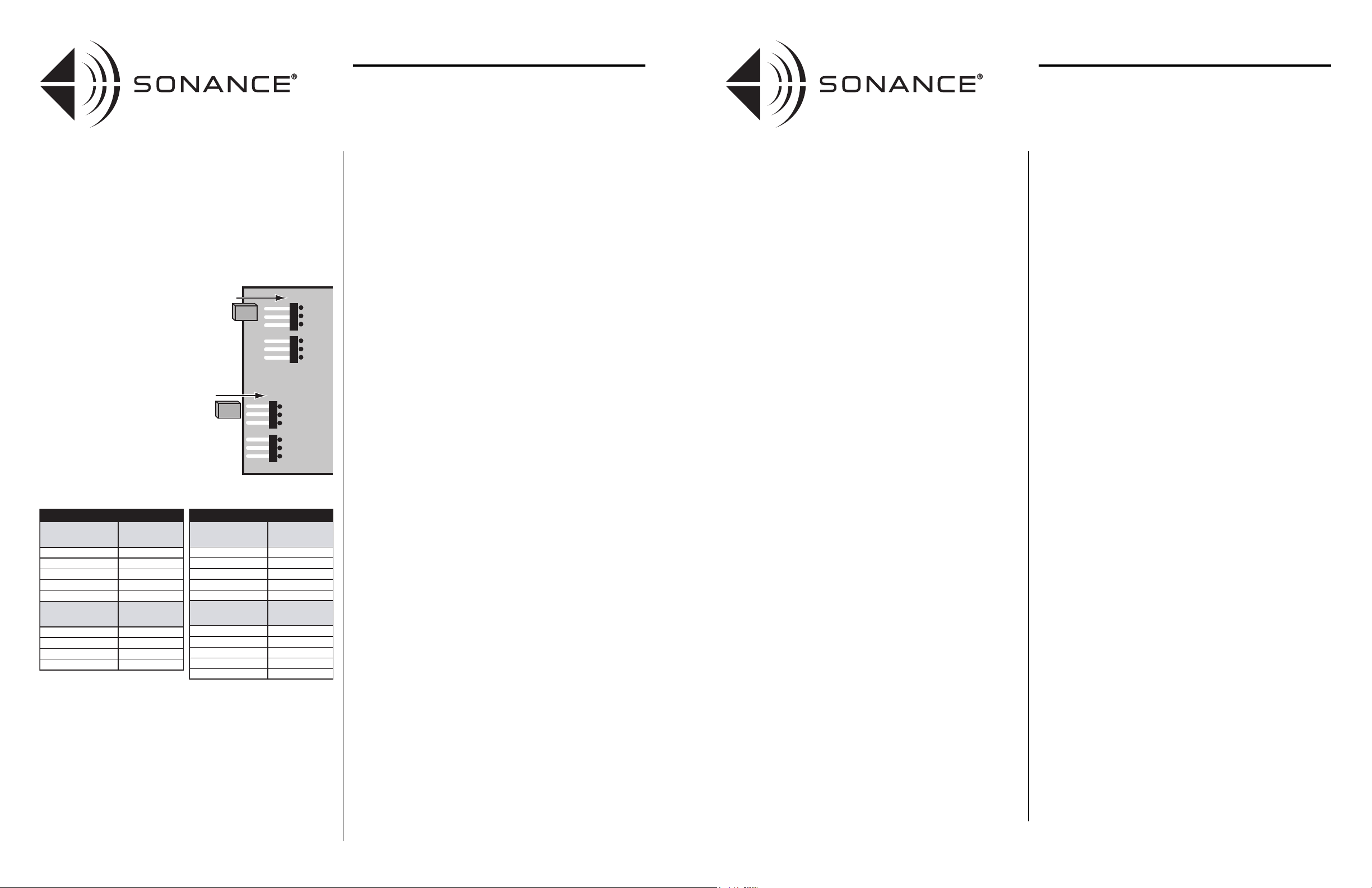
2. Set the impedance jumpers (right)
according to the tables below by slipping
the jumper blocks over the appropriate
pair of blades. (Be sure to set both jumpers.)
WARNING: Operating multiple sets of speakers
through VC60RIM/SIM volume controls with impedance
jumpers set to lower values than recommended in order
to increase the system’s volume capability can damage
the volume controls and amplifier. If the system pro-
duces inadequate volume with the jumpers
set properly, remove some of the speaker/volume
control combinations from that amplifier and add an
additional amplifier(s) to the system to power them.
SETTING THE IMPEDANCE JUMPERS 2:
Advanced Installations (Speakers with Differing Impedances;
Room Balancing)
In addition to protecting amplifiers, the VC60RIM/VC60SIM’s impedance
adjustments can also be used in installations to balance the audio levels in
different-sized rooms, or where speakers of differing impedances are used.
As the impedance seen by the amplifier increases, the output from the amp
into that load decreases. In other words, the impedance jumpers’ X1 setting
will allow the speakers to be louder than if the X8 setting is used.
Here’s how to balance-out room levels using the VC60RIM and VC60SIM:
• Use the
X1
setting for large rooms and outside areas where maximum
volume is needed.
• Use the
X2
and
X4
settings for medium-sized rooms.
• Use the
X8
setting for bathrooms and hallways that need much less overall volume.
With this technique, even though the amplifier will be delivering the same
power to all zones, the speakers connected to the volume controls in the small
rooms (X8 setting) will only achieve a maximum volume that is 9dB lower
than the amplifier's full output. (That's equal to turning the volume control
down three steps from full.)
• The speakers in medium-sized rooms will achieve a maximum output that
is 3dB down (X2 setting) or 6dB down (X4 setting) from maximum.
• Speakers in large rooms and the outside zone (X1 setting) will still achieve a
maximum output level that is equal to the amplifier's full output.
This allows greater output in needy zones while still providing great low level
resolution in the smaller rooms.
Important: All amplifiers need to see a certain minimum load to remain
stable. (Sonamp® amplifiers can handle loads down to 2 ohms before going
into protection.)
When balancing rooms or using speakers with differing impedances,
use the following equation to calculate the overall impedance as seen by the
amplifier:
1/ [ (1 / (SPa x VCa)) + (1 / (SPb x VCb)) + (1 / (SPc x VCc)) + ... (1 / (SPn x VCn)) ]
This equation may look scary but it really is easy to use. The nominal speaker
impedance is represented by SP and the volume control impedance jumper
multiplying factor is shown as VC.
For example, assume that all speakers are 6 ohms nominal. Assume that VCa
(outdoors) is set at X1, VCb (kitchen) is set to X4 and VCc (bathroom) is set
to X8. The equation would be:
1/ [ (1 / (6 x 1)) + (1 / (6 x 4)) + (1 / (6 x 8)) ]
= 1/ [ (1 / 6) + (1 / 24) + (1 / 48) ]
= 1/ [ 0.166 + 0.042 + 0.021 ]
= 1/ 0.229
= 4.37 ohms
The total impedance of this example is above 4 ohms and can be safely driven
by any amp that is stable down to 4 ohms.
Note: If you were using a Sonamp 260 or SAT275 to drive the load in the above
example, the amplifier’s 2-ohm stability would allow you to add even more
rooms. (The number would depend on the speaker impedance and Volume
Control impedance jumper setting.)
INSTRUCTION MANUAL
VC60RIM/VC60SIM
IMPEDANCE-MULTIPLYING
VOLUME CONTROLS
OPERATION:
Setting the Maximum System Volume
Important: After you have set the impedance jumpers as shown on the
previous page, you must set the maximum system volume before operating
the system.
1. If the system has speaker/volume control combinations in more than one
room, determine which room will be played the loudest.
2. Turn the amplifier’s volume control all the way down.
3. Feed the system a strong music signal.
4. Turn the volume control in the “loudest” room all the way up.
5. Gradually advance the amplifier’s volume control until the sound in the
room is as loud as you’re likely to ever want it.
• If you hear audible distortion, lower the amplifier’s volume until
the distortion disappears.
6. Bring the volume control in each room up to the loudest listening level for
that room.
• Leave the volume controls already tested at their loudest listening
level as you test new ones and listen for distortion. If you hear
distortion, lower the amplifier’s volume until the distortion
disappears.
Once the system has been set up in this way, use the volume control in each
room to adjust the volume to that room’s normal listening level. Do not change
the amplifier’s volume.
WARNING: Operating the system at a volume that
causes amplifier clipping will — besides producing
inferior sound quality — saturate the volume control
transformers and can damage the volume controls,
the amplifier and the speakers. If you hear audible
distortion, lower the amplifier’s volume until the
distortion disappears.
If the system produces inadequate volume with the
amplifier’s volume set to just below clipping, remove
some of the speaker/volume control combinations
from that amplifier and add an additional
amplifier(s) to the system to power them.
TECHNICAL ASSISTANCE AND SERVICE
If you have any questions about the operation or installation of this
product, please call our Technical Assistance Department on any busi-
ness day at (800) 582-0772 or (949) 492-7777; from 7 a.m. to 5 p.m.,
Pacific Time.
If your product should need repair or service, contact your Sonance
Authorized Dealer for help, or use the following procedure:
1. Prior to calling, note the product’s model number, serial number, pur-
chase date, and the name and address of the dealer where you pur-
chased the product.
2. Contact our Technical Assistance Department at the above number(s)
and describe the problem the unit is experiencing. If applicable, they
will issue a Return Authorization Number.
IMPORTANT: YOU MUST HAVE PRIOR AUTHORIZATION TO
RETURN YOUR PRODUCT TO SONANCE!
3. If you’re directed to return the unit to Sonance for repair, pack the unit
in its original shipping carton. If needed, you can obtain replacement
packaging from us for a small charge. Please include a copy of the
original bill of sale inside the package.
4. Contact United Parcel Service, Federal Express, or RPS to arrange pre-
paid (not collect) shipping. Do not use the U.S. Mail Service.
IMPORTANT: Freight collect shipments will be refused.
5. Write the Return Authorization Number on the outside of the shipping carton.
6. Ship the packaged unit to:
Quality Assurance Department
Sonance
212 Avenida Fabricante
San Clemente, CA 92672-7531
WARRANTY COVERAGE (U.S. ONLY)
If the unit fails due to a defect in workmanship or material
ffoorr aa ppeerriioodd
ooff ffiivvee ((55)) yyeeaarrss,,
Sonance will, at its option and at no charge, repair or
replace the components of such unit which prove to be defective.
For this warranty to be effective, the bill of sale must show that the unit
was purchased from an "Authorized Sonance Dealer" and must list the
price paid. This warranty shall apply exclusively to the original purchaser
and shall not apply to units purchased for industrial or commercial use.
Furthermore, this warranty shall not apply if:
1) Damage to the unit was caused by accident, abuse, or misuse;
2) The unit was opened, modified, or repaired by unauthorized per-
sonnel; or
3) The unit was not used as outlined in the operating instructions.
EXCLUSIONS AND LIMITATIONS
The warranty set forth above is in lieu of all other warranties, express or
implied, of merchantability, fitness for a particular purpose, or otherwise.
The warranty is limited to Sonance products registered herein and
specifically excludes any damage to loudspeakers and other allied or
associated equipment which may result for any reason from use with this
product. Sonance shall, in no event, be liable for incidental or
consequential damages arising from any breach of this warranty or
otherwise. This warranty gives you specific legal rights, and you may have
other rights which vary from state to state.
Number of 8-Ohm
Speakers
Jumper Position
1 Pair
X
1
2 Pair
X
2
3 – 4 Pair
X
4
5 – 8 Pair X8
Number of 4-Ohm
Speakers
Jumper Position
1 Pair
X
2
2 Pair
X
4
3 – 4 Pair
X
8
More than 4 Pair
Not Recommended
More than 8 Pair
Not Recommended
8-OHM CAPABLE AMPLIFIER
Not RecommendedMore than 16 Pair
Not RecommendedMore than 8 Pair
Number of 8-Ohm
Speakers
Jumper Position
1 – 2 Pair
X
1
X
1
X
2
3 – 4 Pair
X
4
5 – 8 Pair
9 – 16 Pair
X
8
Number of 4-Ohm
Speakers
Jumper Position
1 Pair
X
2
2 Pair
X
4
3 – 4 Pair
X
8
5 – 8 Pair
4-OHM CAPABLE AMPLIFIER
X1
X2
X4
X8
X1
X2
X4
X8
2
INSTRUCTION MANUAL
VC60RIM/VC60SIM
IMPEDANCE-MULTIPLYING
VOLUME CONTROLS
3