Loading ...
Loading ...
Loading ...
5
ENGLISH
SAVE THESE INSTRUCTIONS FOR
FUTURE USE
Intended Use
This planer is designed for wood working.
DO NOT use under wet conditions or in presence of
flammable liquids orgases.
DO NOT let children come into contact with the tool.
Supervision is required when inexperienced operators use
thistool.
ASSEMBLY
WARNING: To reduce the risk of serious personal
injury, turn unit off and disconnect it from
power source before making any adjustments or
removing/installing attachments or accessories.
An accidental start-up can causeinjury.
Assembly Tools Required
• 5 mm hex wrench (included)
Assembly Time Estimate
Assembly for this machine takes approximately 30 minutes.
Unpacking and Cleaning
Carefully unpack the machine and all loose items from the
shipping container(s). Remove the rust-preventative oil
from unpainted surfaces using a soft cloth moistened with
mineral spirits, paint thinner or denatured alcohol.
NOTICE: Do not use highly volatile solvents such as
gasoline, naphtha, acetone or lacquer thinner for
cleaning your machine.
After cleaning, cover the unpainted surfaces with a good
quality household floor paste wax.
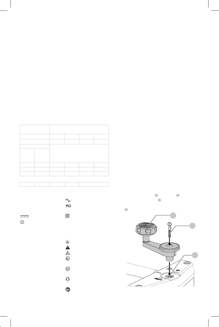
Elevating Handle (Fig. A, D)
Attach the elevating handle
3
to the shaft
8
and fasten in
place with M5 x 20 mm screw
7
. NOTE: Ensure that the
flats of the handle and the flats on the shaft are aligned. Flip
handle
3
.
Fig.D
3
7
8
12 16 14 12 Not Recommended
The label on your tool may include the following symbols. The
symbols and their definitions are asfollows:
V ......................... volts
Hz .......................hertz
min ..................... minutes
or DC ......direct current
...................... Class I Construction
(grounded)
…/min ..............per minute
BPM .................... beats per minute
IPM ..................... impacts per minute
RPM .................... revolutions per
minute
sfpm ................... surface feet per
minute
SPM .................... strokes per minute
A ......................... amperes
W ........................watts
kg ........................kilograms
mm .....................millimeters
or AC ...........alternating current
or AC/DC .... alternating or
direct current
...................... Class II
Construction
(double insulated)
n
o
.......................no load speed
n .........................rated speed
......................earthing terminal
.....................safety alert symbol
.....................visible radiation
..................... wear respiratory
protection
..................... wear eye
protection
..................... wear hearing
protection
..................... read all
documentation
Minimum Gauge for Cord Sets
Volts
Total Length of Cord in Feet
(meters)
120 V 25 (7.6) 50 (15.2) 100 (30.5) 150 (45.7)
240 V 50 (15.2) 100 (30.5) 200 (61.0) 300 (91.4)
Ampere Rating
American Wire Gauge
More
Than
Not
More
Than
0 6 18 16 16 14
6 10 18 16 14 12
10 12 16 16 14 12
NOTE: In Canada, the use of a temporary adapter is not
permitted by the Canadian Electric Code.
DANGER: In all cases, make certain that the
receptacle in question is properly grounded. If you
are not sure, have a qualified electrician check
thereceptacle.
EXTENSION CORDS
WARNING: Use proper extension cords. Make sure
your extension cord is in good condition and is a
3-wire extension cord which has a 3-prong grounding
type plug and matching receptacle which will accept
the machine’s plug. When using an extension cord,
be sure to use one heavy enough to carry the current
of the machine. An undersized cord will cause a
drop in line voltage, resulting in loss of power and
overheating. Minimum Gauge for Cord Sets
shows the correct gauge to use depending on the cord
length. If in doubt, use the next heavier gauge. The
smaller the gauge number, the heavier the cord.
Loading ...
Loading ...
Loading ...