USER MANUAL Dual Fuel Portable Generator
QUICK START GUIDE (GASOLINE)
1. Remove shipping braces
- The shipping braces prevent engine movement during shipment. Flip the generator over and remove the brightly colored brace between the motor and the frame, and the wood brace under the generator.
2. Add oil
- The oil fill cap is located on the lower engine block to the right of the recoil start housing. Remove the oil fill cap and fill with 10w30 oil.
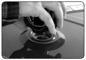
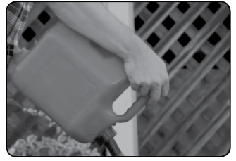
3. Add gasoline

- The fuel cap is located on top of the fuel tank. Fill the tank with fresh unleaded gasoline 87 octane or higher. The tank is full when you see fuel in the bottom of the fuel filter cup. DO NOT overfill the tank.
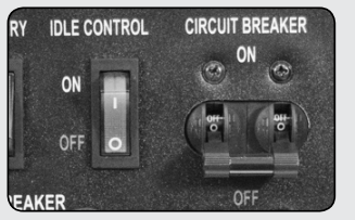
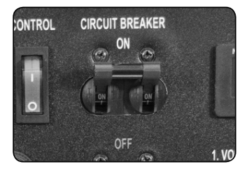
4. Turn breaker off
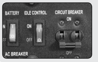
- The breaker is located on the right side of the front power panel. Flip the breaker down to prevent accidental load when starting the generator.
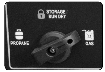
5. Turn fuel switch to GAS
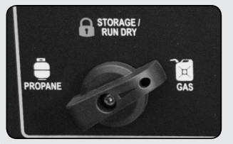
- The fuel switch is located on the left front panel. Rotate the switch clockwise to the GAS position to turn on the gas supply.
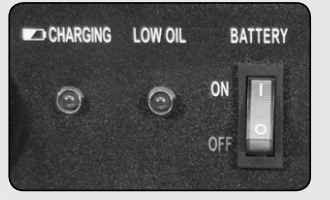
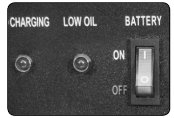
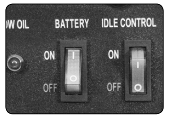
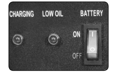
6. Turn battery switch on

- The battery switch is located on the top center of the main power panel. Turn the switch ON to allow power to the push button start.
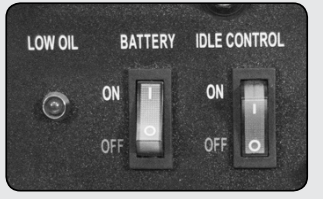
7. Turn idle control off
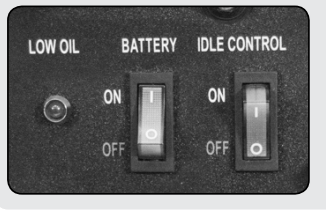
- The idle control is located on the top center of the main power panel. Turn the switch OFF to prevent the unit trying to idle down before the engine is warmed up
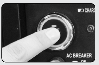
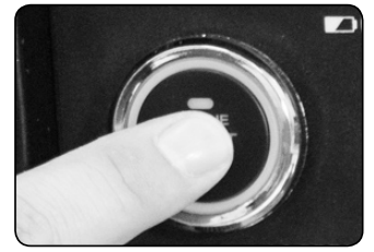
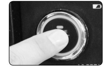
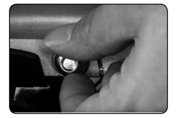
8. Start generator
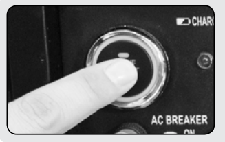
- The push button start left side of the main power panel. Press the button for 1 second to start the generator.
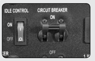
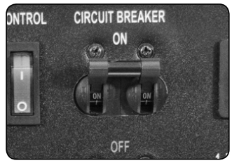
9. Turn breaker on
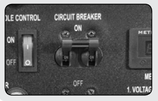
- The breaker is located on the right side of the front power panel. Flip the breaker up to allow power to flow to the receptacles.
10. Connect devices
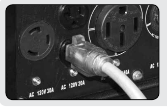
- Connect your devices to the receptacles on the front panel. Start with the largest loads first.
QUICK START GUIDE (PROPANE)
1. Remove shipping braces
- The shipping braces prevent engine movement during shipment. Flip the generator over and remove the brightly colored brace between the motor and the frame, and the wood brace under the generator.
2. Add oil
- The oil fill cap is located on the lower engine block to the right of the recoil start housing. Remove the oil fill cap and fill with 10w30 oil.
3. Turn breaker off
- The breaker is located on the right side of the front power panel. Flip the breaker down to prevent accidental load when starting the generator.
4. Turn fuel switch to Propane
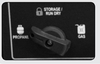
- The fuel switch is located on the left front panel. Rotate the switch counter-clockwise to the Propane position to turn on the fuel supply.
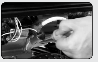
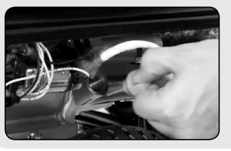
5. Connect propane hose
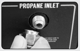
- The propane inlet is located on the right hand front panel to the right of the fuel switch. Securely connect the propane hose to the inlet.
6. Connect propane tank

- The propane hose is located on the left side of the regulator, below the OHV valve cover. Screw the open ACME nut connection to your propane tank and turn the tank on.
7. Turn battery switch on
- The battery switch is located on the top center of the main power panel. Turn the switch ON to allow power to the push button start.
8. Turn idle control off
- The idle control is located on the top center of the main power panel. Turn the switch OFF to prevent the unit trying to idle down before the engine is warmed up.
9. Start generator
- The push button start left side of the main power panel. Press the button for 1 second and release to start the generator.
10. Turn breaker on / connect
- The breaker is located on the right side of the front power panel. Flip the breaker up to allow power to flow to the receptacles. Connect your devices to the receptacles on the front panel. Start with the largest loads first.Turn breaker on / connect The breaker is located on the right side of the front power panel. Flip the breaker up to allow power to flow to the receptacles. Connect your devices to the receptacles on the front panel. Start with the largest loads first.
GENERATOR COMPONENTS
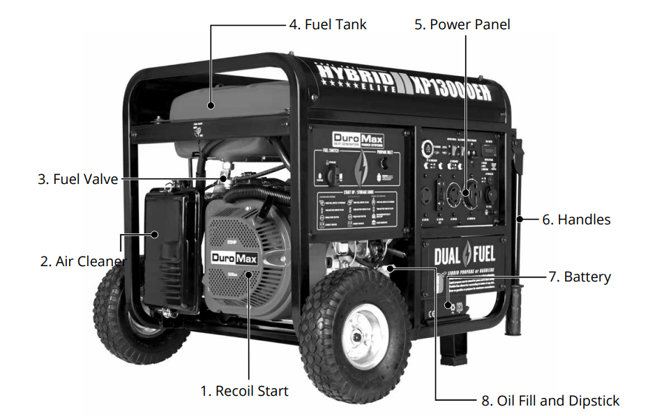
1. Recoil Start – Easy Pull Recoil Start to start the engine without the electric start.
2. Air Cleaner - a removable, cleanable, oiled, element that cleans the air going into the engine.
3. Fuel Valve - On/Off valve that allows gasoline to the fuel switch.
4. Fuel Tank - All metal 7.8 Gallon gasoline fuel tank.
5. Power Panel - Contains the start switch, plugs, meters, and circuit breakers.
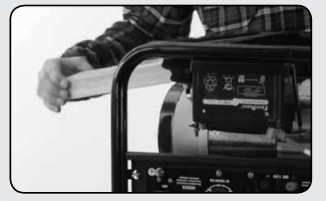
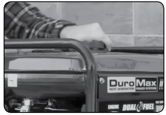
6. Handles - Longest handles of any DuroMax Model allow easy movement across any surface.ad.
7. Battery - 12V DC 7ah Battery that powers the Electric Start System
8. Oil Fill and Dipstick - Use to add or check the oil.
9. Fuel Switch - Fuel selection switch to choose Gas, Propane, or Storage mode.
10. Propane Inlet - Provides a regulated LPG Fuel supply to the engine. (Intended for use with a LPG Source of 3 PSI or more.)
11. Engine Switch – Push Button start switch. Press for 1 second to start the generator. Hold for 3 seconds to stop the generator.
12. Charging Light - Will light when the generator is charging the onboard battery
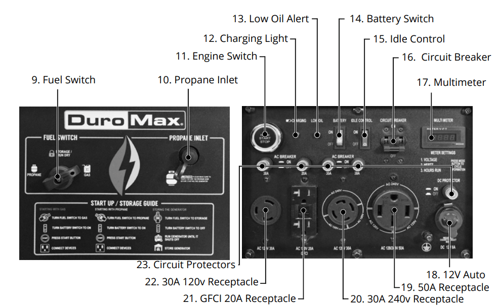
13. Low Oil Alert – Will light only if the generator shuts down due to low oil.
14. Battery Switch – Prevents battery discharge during storage.
15. Idle Control - Slows the engine to save fuel and lower noise when no load.
16. Circuit Breaker - Protects the panel from overload and short circuits.
17. Multimeter – Displays voltage, hertz, and time running.
18. 12v Auto - Provides a 12v automotive style plug for appliances and chargers.
19. 120/240v 4-Prong Receptacle - Use to connect electrical devices that run 120 or 240 Volt, 60Hz, single phase, AC current (NEMA 14-50)
20. 120/240v 4-Prong Twist Lock - Use to connect electrical devices that run 120 or 240 Volt, 60Hz, single phase, AC current (NEMA 14-30)
21. 120v 3-Prong GFCI Receptacle - Use to connect electrical devices that run 120 Volt, 60Hz, single phase, AC current (NEMA 5-20)
22. 120v 3-Prong Twist Lock - Use to connect electrical devices that run 120 Volt, 60 Hz, single phase, AC current (L5-30).
23. Circuit Protectors - Protects the receptacles from overload.
GENERATOR SETUP
Step 1 - Remove Shipping Braces
1. Unpack
a. Remove the generator from the box.
b. Place the largest piece of packing foam on a flat surface.
c. Flip the generator upside down on the pad.
CAUTION: NEVER Attempt this if you have put fuel or oil in the generator.

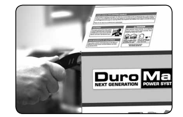
2. Remove braces
a. Completely remove each of the 4 bolts holding the orange metal brace in place.
b. Remove the brace.
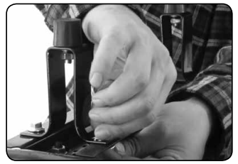
c. Cut the nylon tie strap holding the wood brace in place.
d. Grab the end of the second brace and pull it out.
e. This piece is no longer needed and can be discarded.
 Note: Shipping braces can be thrown away. They will not be needed again.
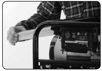
Step 2 - Wheel Kit Installation (Optional)
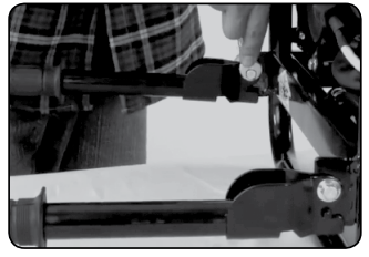
1. Install support legs
- Secure the support legs to the frame with provided bolts and lock nuts.
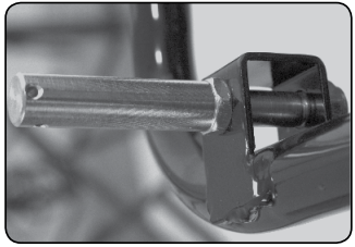
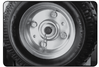
2. Install wheels
a. Insert wheel bolt through frame and secure with provided nut.
b. Slide one wheel over each axle end and secure with the provided retaining pins.
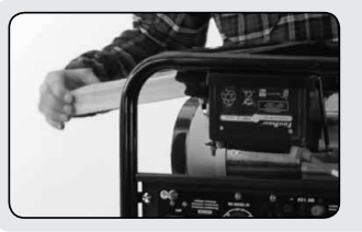
3. Install Handles
- Attach the handles to the brackets on the frame using the provided bolts and nuts.
Step 3 - Adding Oil
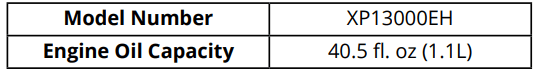
The generator requires engine oil to operate properly. The generator, when new from the package contains no oil in the crankcase* . You must add the proper amount of oil before operating the generator for the first time. This amount is equal to the oil capacity of the engine crankcase:
WARNING: Do not apply engine oils with additives or 2-stroke gasoline engine oils. They don’t have enough lubrication, and may shorten the engine’s service life.
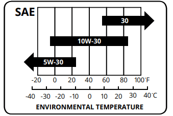
Engine oil recommended: SAE 10W-30. Viscosity varies with regions and temperatures. Choose your oil viscosity using the chart to the left.
* A small amount of oil from factory testing may be present on arrival.
1. Add oil
a. Make sure the generator is on a level surface.
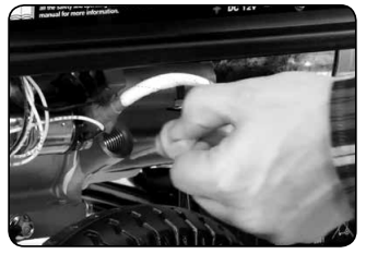
b. Unscrew the oil filler/dipstick cap from the engine .
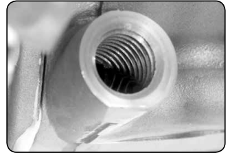
c. Using a funnel, add the appropriate amount of oil into the crankcase. You will know the crankcase is full when the oil level has reached the lower lip of the opening you have just poured the oil into.
d. Replace oil filler cap.
Step 4 - Adding Gasoline
2. Add Gasoline
a. Make sure the generator is on a level surface.
b. Unscrew gas cap and set aside (NOTE: the gas cap may be tight and hard to unscrew).
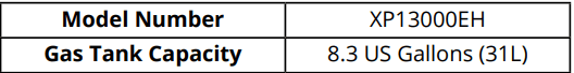
c. Slowly add unleaded gasoline to the fuel tank. Be careful not to overfill. Please refer to the chart below to find the gas capacity of your generator model. The fuel gauge on the top of the gas tank indicates how much gasoline is in the generator gas tank.
d. Replace fuel cap and wipe up any spilled gasoline with a dry cloth.
NOTE: Gas can expand. Do not fill the gas tank to the very top. Leave a minimum of 1.5 in of open space.
IMPORTANT:
- Never use an oil/gasoline mixture. Never use old gas.
- Avoid getting dirt or water in the fuel tank.
- Gas can age in the tank and make it hard to start up the generator in the future.
- Never store generator for extended periods of time with fuel in the tank.
Step 5 - Grounding the Generator
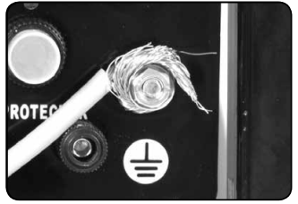
1. Attach grounding wire
a. Ground the generator by tightening the grounding nut against a grounding wire.
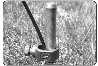
b. Connect the other end to a copper or brass grounding rod that’s driven into the earth.
A generally acceptable grounding wire is a No. 12 AWG (American Wire Gauge) stranded copper wire.
Grounding codes can vary by location. Please contact a local electrician to check the grounding regulations for your area.
High Altitude Operation
- At high altitude, the standard carburetor air/fuel mixture will be too rich. Performance will decrease, and fuel consumption will increase. A very rich mixture will also foul the spark plug and cause hard starting. Operation at an altitude that differs from that at which this engine was certified, for extended periods of time, may increase emissions. High altitude performance can be improved by specific modifications to the carburetor. If you always operate your generator at altitudes above 5,000 feet (1,500 meters), have a dealer perform this carburetor modification. This engine, when operated at high altitude with the carburetor modifications for high altitude use, will meet each emission standard throughout its useful life. Even with carburetor modification, engine horsepower will decrease about 3.5% for each 1,000-foot (300-meter) increase in altitude. The effect of altitude on horsepower will be greater than this if no carburetor modification is made.
- When the carburetor has been modified for high altitude operation, the air/fuel mixture will be too lean for low altitude use. Operation at altitudes below 5,000 feet (1,500 meters) with a modified carburetor may cause the engine to overheat and result in serious engine damage.
STARTING THE GENERATOR
Starting the Generator Using Gasoline

1. Turn breaker OFF
- The breaker is located on the right side of the front power panel. Flip the breaker down to prevent accidental load when starting the generator.
2. Turn fuel switch to GAS
- The fuel switch is located on the left front panel. Rotate the switch clockwise to the GAS position to turn on the gas supply
3. Turn battery switch ON
- The battery switch is located on the top center of the main power panel. Turn the switch ON to allow power to the push button start.
4. Turn idle control OFF
- When the engine starts, allow the engine switch to return to the ON position.
5. Start the Generator
- The push button start left side of the main power panel. Press the button for 1 second and release to start the generator.
6. Turn breaker ON / Connect
- The breaker is located on the right side of the front power panel. Flip the breaker up to allow power to flow to the receptacles. Connect your devices to the receptacles on the front panel. Start with the largest loads first.
Starting the Generator Using Propane
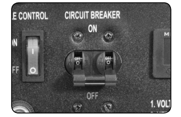
1. Turn breaker off
- The breaker is located on the right side of the front power panel. Flip the breaker down to prevent accidental load when starting the generator.
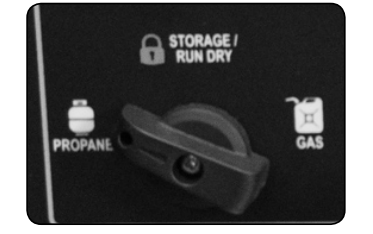
2. Turn fuel switch to Propane
- The fuel switch is located on the left front panel. Rotate the switch counter-clockwise to the Propane position to turn on the fuel supply
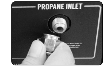
3. Connect propane hose
- The propane inlet is located on the right hand front panel to the right of the fuel switch. Securely connect the propane hose to the inlet.

4. Connect propane tank
- There propane hose is located on the left side of the regulator, below the OHV valve cover. Screw the open ACME nut connection to your propane tank and turn the tank on.
5. Turn battery switch ON
- The battery switch is located on the top center of the main power panel. Turn the switch ON to allow power to the push button start.
6. Start
- The push button start left side of the main power panel. Press the button for 1 second and release to start the generator.
7. Turn breaker on / connect
- The breaker is located on the right side of the front power panel. Flip the breaker up to allow power to flow to the receptacles. Connect your devices to the receptacles on the front panel. Start with the largest loads first.
MAINTENANCE AND CARE
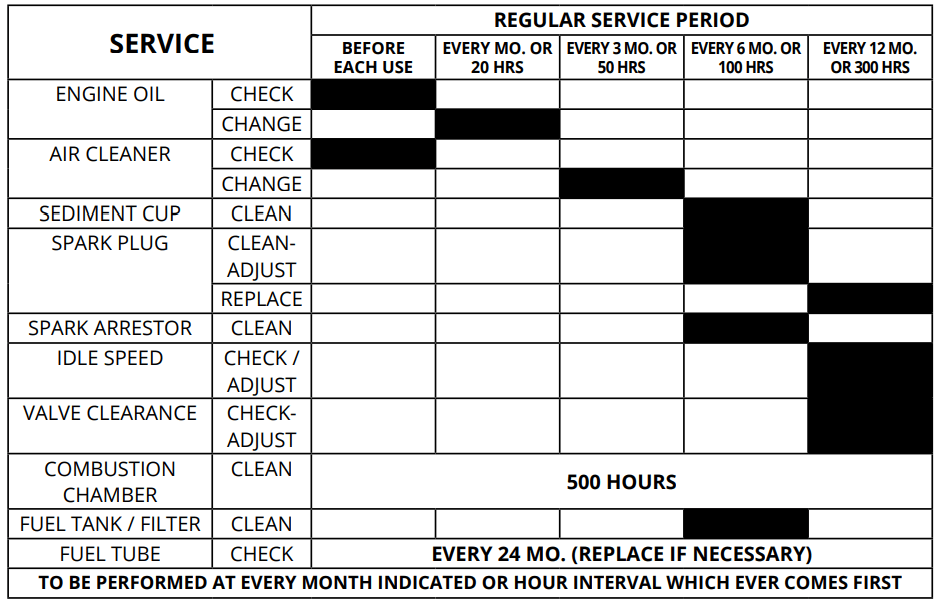
Maintenance Schedule
Remember that this schedule is based on the assumption that your machine will be used for its designed purpose. Sustained high-load, high temperature operation, or use in unusually wet or dusty conditions, will require more frequent service.
Checking the oil
1. Check the oil
The generator is equipped with an automatic shutoff to protect it from damage due to low oil. Nonetheless, you should check the oil level of the engine before each use to ensure that the engine crankcase has a sufficient amount.
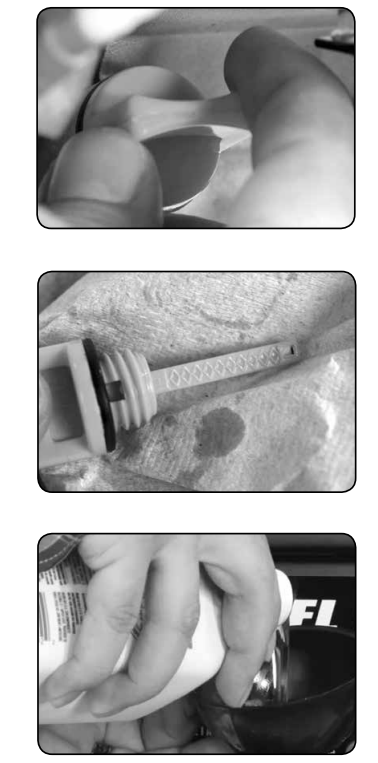
To check the oil level:
a. Make sure the generator is on a level surface.
b. Unscrew the oil filler/dipstick cap.
c. With a dry cloth, wipe the oil off of the stick on the inside of the cap.
d. Insert the dipstick as if you were replacing the cap and then remove again. There should now be oil on the stick. If there is no oil on the stick, or oil only at the very end of the stick, you should add oil until the engine crankcase is filled (see “Adding Oil” portion of the “Maintenance” section).
e. Be sure to replace the cap when finished checking oil.
NOTE: The oil capacity for your generator can be found in the “Specifications” section of this manual.
Changing the oil
Worn out or dirty oil does not cool the generator properly and can lead to catastrophic engine damage.
In addition to regular oil changes, it is necessary to drain the oil from the crankcase if it has become contaminated with water or dirt.
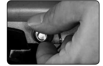
1. Remove drain plug
- Using a 10 mm hex wrench, unscrew the oil drain plug, which is located on the crankcase underneath the oil filler/dipstick cap.
- Allow all the oil to drain from the generator.

2. Drain oil
- Drain oil into an approved oil disposal container. Contact your local auto parts store for information on oil disposal.
3. Replace drain plug
- Replace the oil drain plug and tighten with a 10 mm hex wrench.
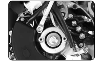
SPECIFICATIONS
TROUBLESHOOTING
Engine will not start
- Engine Switch is “Off”
- Set engine switch to “run”
- Fuel Valve is “Closed”
- Turn fuel valve to “open”
- Choke is open
- Engine is out of fuel
- Fuel is old or contaminated
- Spark Plug is dirty
- Spark Plug is broken
- Generator is not level
- Move generator to a level surface
- Oil is low.
Engine runs, but there is no electrical output
- Circuit breaker is “Off”
- Turn “on” circuit breaker
- Wiring connection is bad
- Replace extension cord(s)
- Device connected to generator is malfunctioning
- Disconnect malfunctioning device
Generator runs, but does not support all electrical devices connected
- Generator is overloaded
- Disconnect 1 or more items to reduce the load
- Device connected to generator is bad
- Disconnect malfunctioning device
- Air Cleaner is dirty.
- Clean / replace the air filter
Changing / Inspecting the Carbon Brushes
The carbon brushes in conjunction with the AVR regulates power from the generator. The carbon brushes are wearable parts and should be inspected every 250 running hours.
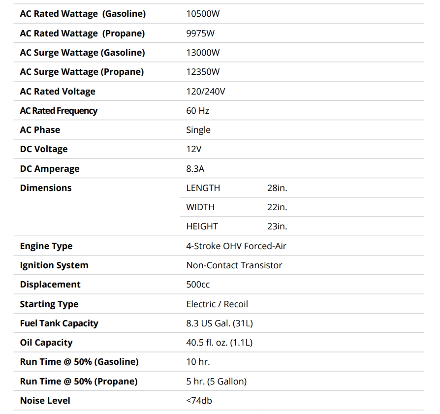
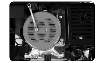
1. Remove generator cover
- Remove the 2 bolts of the generator cover then pull the cover off the generator.
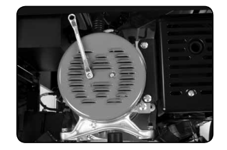
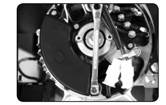
2. Remove bolt from brush
- Remove the bolt holding the carbon brush.
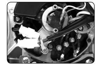
3. Disconnect AVR wires
- Remove the two wires from the AVR on the carbon brush
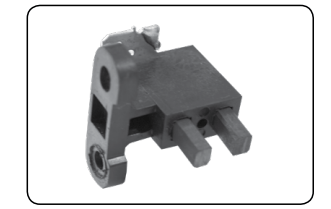
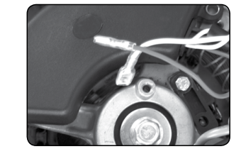
4. Install new brush
- Install new carbon brush with bolt.
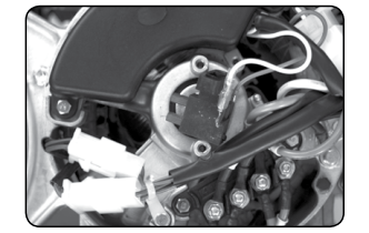
5. Connect AVR wires
- Insert and connect the 2 wires from the AVR, be sure to connect + and – correctly.
6. Replace generator cover
- Replace the back cover of the generator and secure with the 2 bolts
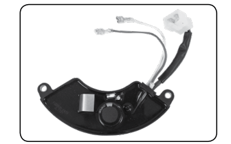
Changing / Inspecting the AVR
The carbon brushes in conjunction with the AVR regulates power from the generator. If the generator is overheated or overloaded, the AVR may be damaged and require replacement.
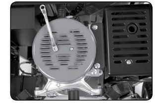
1. Remove generator cover
- Remove the 2 bolts of the generator cover then pull the cover off the generator.
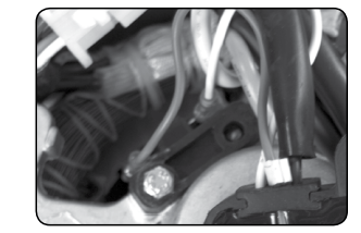
2. Remove AVR bolts
- Remove the 2 bolts holding the AVR.
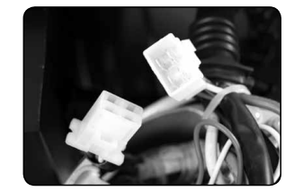
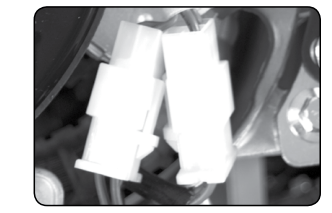
3. Disconnect AVR wire clip
- Disconnect the wire clip.
4. Disconnect wires from brush
- Remove the 2 wires from the AVR on the carbon brush.
5. Install new AVR
- Install the new AVR with the 2 bolts.
6. Reconnect wires to brush
7. Reconnect the AVR wire clip
- Insert and connect the 2 wires from the AVR, be sure to connect + and – correctly

8. Replace generator cover
- Replace the back cover of the generator and secure with the 2 bolts.
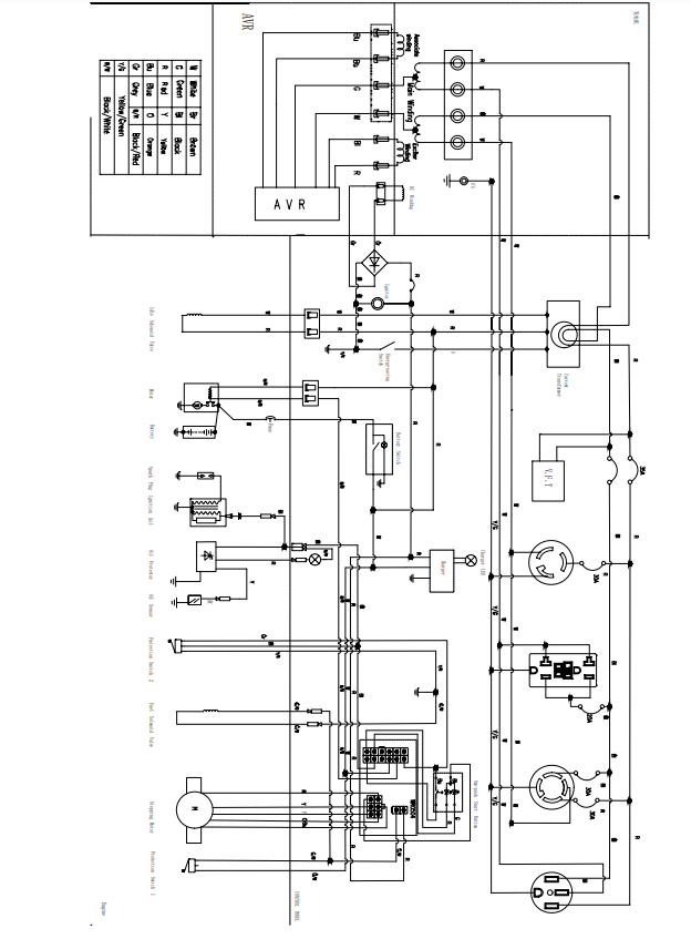
WIRING DIAGRAM