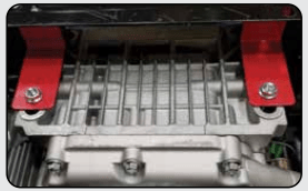
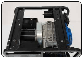
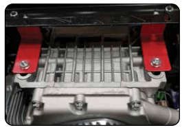
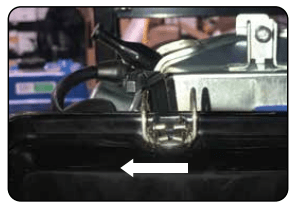
The shipping braces prevent engine movement during shipment. Flip the generator over and remove the brightly colored brace between the motor and the frame, and the wood brace under the generator.
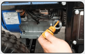
2. Add oil
The oil fill cap is located on the lower engine block to the right of the recoil start housing. Remove the oil fill cap and fill with 10w30 oil.
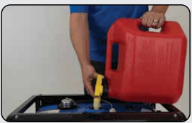
3. Add gasoline
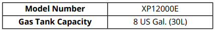
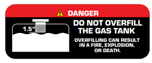
The fuel cap is located on top of the fuel tank. Fill the tank with fresh unleaded gasoline 87 octane or higher. The tank is full when you see fuel in the bottom of the fuel filter cup. DO NOT overfill the tank.
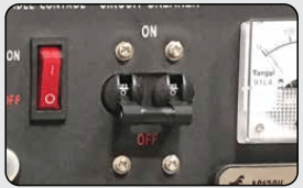
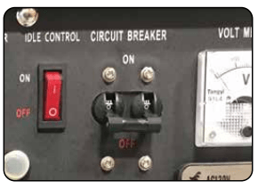
4. Turn breaker off
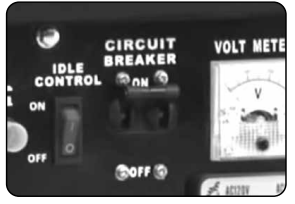
The breaker is located on the right side of the front power panel. Flip the breaker down to prevent accidental load when starting the generator.
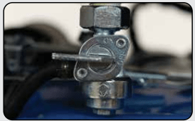
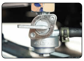
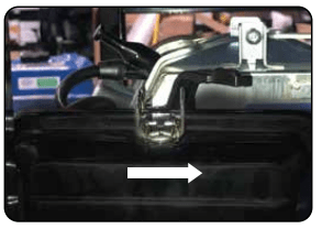
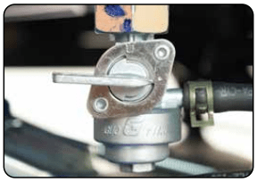
5. Turn gas valve on
The gas valve is located above the recoil start on the bottom of the fuel tank. Rotate the valve counterclockwise to the vertical position to turn on the gas supply.
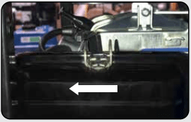
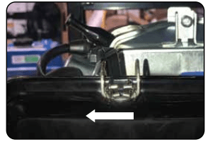
6. Close choke
The choke lever is located above the air filter to the left of the recoil start. Slide the lever to the left to cut the air supply and allow more gas into the engine to start.
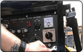
7. Start generator
The switch is located on the left side of the front power panel. Press the switch up to the start position to start the generator. Allow the switch to return to the run position once started.
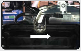
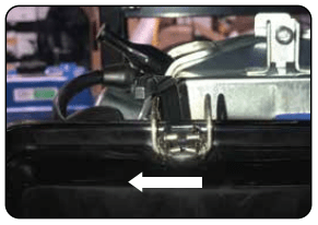
8. Open choke
The choke lever is located above the air filter to the left of the recoil start. Slide the lever to the right to open the choke and increase air into the carburetor for normal running
9. Turn breaker on
The breaker is located on the right side of the front power panel. Flip the breaker up to allow the power to flow to the receptacles.
10. Connect devices
Connect your devices to the receptacles on the front panel. Start with the largest loads first.
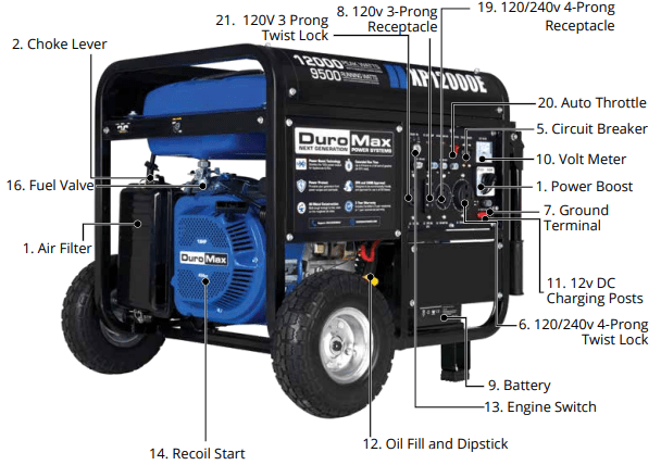
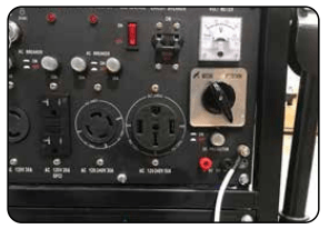
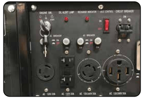
GENERATOR COMPONENTS
1. Air Cleaner - a removable, cleanable, oiled, element that cleans the air going into the engine.
2. Choke Lever - Allows the airflow into the carburetor to be restricted to assist in starting the engine.
3. Fuel Gauge - Indicates the amount of fuel in the gasoline tank.
4. Fuel Cap - Allows access to fill the gasoline tank.
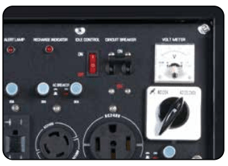
5. Circuit Breaker - Resettable switch that protects the generator from electrical overload.
6. 120/240v 4-Prong Twist Lock - Use to connect electrical devices that run 120 or 240 Volt, 60Hz, single phase, AC current (NEMA L14-30).
7. Ground Terminal - Connect a ground wire here to properly ground the generator.
8. 120v 3-Prong Receptacle - Use to connect electrical devices that run 120 Volt, 60 Hz, single phase, AC current (NEMA 5-20).
9. Battery - 12V DC 7ah Battery that powers the Electric Start System.
10. Volt Meter - Provides reading of voltage output.
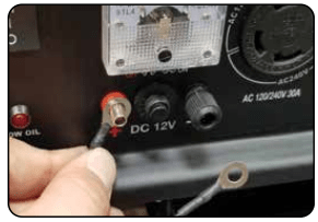
11. 12v DC Charging Posts – DC Output for charging batteries or running small DC powered items.
12. Oil Fill and Dipstick - Use to add or check the oil.
13. Engine Switch – 3 Position Switch to “Start”, “Run”, or turn “Off” the generator.
14. Recoil Start – Easy Pull Recoil Start to start the engine without the electric start.
15. Fuel Filter Cup - Traps dirt and debris in gasoline before it enters the engine.
16. Fuel Valve - On/Off Valve that allows fuel into the engine.
17. Spark plug – Provides ignition to the engine.
18. Muffler – Reduces engine emissions and reduces noise.120v 3-Prong Twist Lock - Use to connect electrical devices that run 120 Volt, 60 Hz, single phase, AC current (L5-30).
19. 120/240v 4-Prong Receptacle - Use to connect electrical devices that run 120 or 240 Volt, 60Hz, single phase, AC current (NEMA 14-50).
20. Auto Throttle - Allows the engine to run at reduced speed when no load is present to save on fuel and reduce noise levels.
GENERATOR SETUP
Step 1 - Remove Shipping Braces
1. Unpack
a. Remove the generator from the box.
b. Place the largest piece of packing foam on a flat surface.
c. Flip the generator upside down on the pad.
CAUTION: NEVER Attempt this if you have put fuel or oil in the generator.
2. Remove braces
The shipping braces prevent engine movement during shipment. Flip the generator over and remove the brightly colored braces between the motor and the frame, and the wood brace under the generator.
Note: Shipping braces can be thrown away. They will not be needed again.
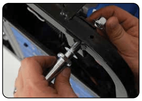
Step 2 - Wheel Kit Installation (Optional)
1. Install support legs
a. Secure the support legs to the frame with the provided lock nuts.
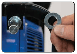
2. Install wheel axles
a. Place the smallest washer onto the wheel axle bolts.
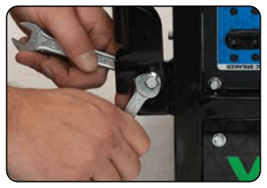
b. Insert wheel axle bolts through the frame and secure with the provided nut and wrenches
3. Install inside wheel washers
a. Place one of the large washers onto the axles.
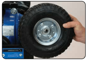
4. Install wheels
a. Place the wheels onto the axles.
5. Install outside wheel washers
a. Place the other large washers onto the axles.
6. Install cotter pins
a. Place the cotter pin through the hole at the end of the axle and bend it out to secure the wheel.
7. Install handles
a. Attach the handles to the brackets on the frame using the provided bolts and nuts.
Do not overtighten the handles, it will prevent free movement.
8. Flip over assembled
a. Flip the assembled generator over onto its wheels and support brackets.
Step 3 - Connect the Battery
1. Remove the battery cover
a. Remove the battery cover plate using the wrench from the toolkit.
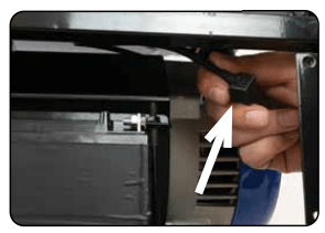
2. Locate the negative cable
a. Locate the negative battery cable above and behind the battery. One side is connected to ground and the other end needs to be connected to the battery.
b. Route the free end to the negative battery terminal.
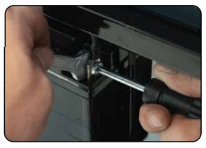
3. Connect the negative cable
a. Push the black rubber boot up the wire to expose the connector.
b. Securely connect the free end of the battery cable to the negative battery terminal using the screw and nut from the battery with the screwdriver and wrench from the toolkit.
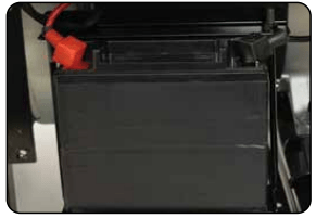
4. Reinstall the battery plate
a. Cover the connected terminal with the black rubber boot.
b. Reinstall the battery cover plate using the wrench from the toolkit.
Step 4 - Adding Oil
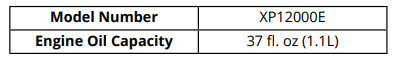
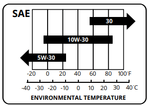
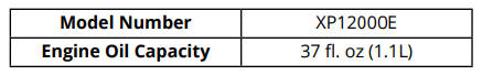
The generator requires engine oil to operate properly. The generator, when new from the package, contains no oil in the crankcase* . You must add the proper amount of oil before operating the generator for the first time. This amount is equal to the oil capacity of the engine crankcase:
WARNING: Do not apply engine oils with additives or 2-stroke gasoline engine oils. They don’t have enough lubrication and may shorten the engine’s service life.
Engine oil recommended: SAE 10W-30. Viscosity varies with regions and temperatures. Choose your oil viscosity using the chart to the left.
* A small amount of oil from factory testing may be present on arrival.
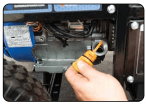
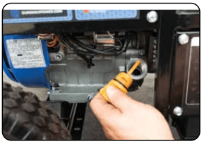
Add oil
a. Make sure the generator is on a level surface.
b. Unscrew the oil filler/dipstick cap from the engine.
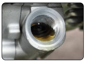
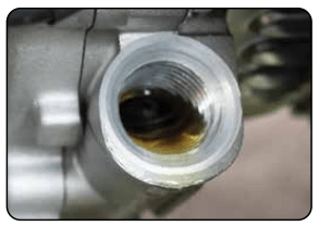
c. Using a funnel, add the appropriate amount of oil into the crankcase. You will know the crankcase is full when the oil level has reached the lower lip of the opening you have just poured the oil into.
d. Replace the oil filler cap.
WARNING: DO NOT overfill the crankcase. This may damage the motor and shorten the overall life of your generator.
Step 5 - Adding Gasoline (Optional)
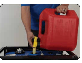
Add Gasoline
a. Make sure the generator is on a level surface.
b. Unscrew gas cap and set aside (NOTE: the gas cap may be tight and hard to unscrew).
c. Slowly add unleaded gasoline to the fuel tank. Be careful not to overfill. The fuel gauge on the top of the gas tank indicates how much gasoline is in the generator gas tank.
d. Replace fuel cap and wipe up any spilled gasoline with a dry cloth.
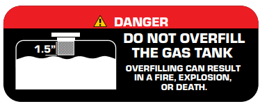
WARNING: Gas can expand. Do not fill the gas tank to the very top. Leave a minimum of 1.5 in open space.
Gasoline and gas fumes are highly flammable.
Do not fill the tank near an open flame.
Always check for fuel spills.
IMPORTANT:
To ensure that the generator runs smoothly use only FRESH, UNLEADED GAS WITH AN OCTANE RATING OF 87 OR HIGHER.
Never use an oil/gasoline mixture. Never use old gas.
Avoid getting dirt or water in the fuel tank.
Gas can age in the tank and make it hard to start up the generator in the future.
Never store generator for extended periods of time with fuel in the tank.
Step 6 - Grounding the Generator
Attach grounding wire
a. Ground the generator by tightening the grounding nut against a grounding wire.
b. Connect the other end to a copper or brass grounding rod that’s driven into the earth.
A generally acceptable grounding wire is a No. 12 AWG (American Wire Gauge) stranded copper wire.
Grounding codes can vary by location. Please contact a local electrician to check the grounding regulations for your area.
WARNING: Failure to properly ground the generator can result in electrocution.
High Altitude Operation
At high altitudes, the standard carburetor air/fuel mixture will be too rich. The performance will decrease, and fuel consumption will increase. A very rich mixture will also foul the spark plug and cause hard starting. Operation at an altitude that differs from that at which this engine was certified, for extended periods of time, may increase emissions. High altitude performance can be improved by specific modifications to the carburetor. If you always operate your generator at altitudes above 3,000 feet (900 meters), have a dealer perform this carburetor modification. This engine, when operated at high altitude with the carburetor modifications for high altitude use, will meet each emission standard throughout its useful life. Even with carburetor modification, engine horsepower will decrease by about 3.5% for each 1,000-foot (300-meter) increase in altitude. The effect of altitude on horsepower will be greater than this if no carburetor modification is made.
When the carburetor has been modified for high altitude operation, the air/fuel mixture will be too lean for low altitude use. Operation at altitudes below 3,000 feet (900 meters) with a modified carburetor may cause the engine to overheat and result in serious engine damage.
BEFORE YOU START YOUR GENERATOR
Step 1 - Check the oil
Check the oil
The generator is equipped with an automatic shutoff to protect it from damage due to low oil. Nonetheless, you should check the oil level of the engine before each use to ensure that the engine crankcase has a sufficient amount.
To check the oil level:
a. Make sure the generator is on a level surface.
b. Unscrew the oil filler/dipstick cap.
c. With a dry cloth, wipe the oil off of the stick on the inside of the cap.
d. Insert the dipstick as if you were replacing the cap and then remove it again. There should now be oil on the stick. If there is no oil on the stick, or oil only at the very end of the stick, you should add oil until the engine crankcase is filled (see “Adding Oil” portion of the “Maintenance” section).
e. Be sure to replace the cap when finished checking oil.
Step 2 - Check the gas level (Optional)
Check fuel level
If running the engine on gasoline check to see that there is sufficient gasoline in the fuel tank. The fuel gauge on top of the tank will give a rough estimate of the gasoline level. The gauge will appear white then fill red as the tank is filled.
Note: Fuel gauge may not register with less than 1/3 fuel tank full.
WARNING: Gasoline and gasoline fumes are highly flammable.
Do not fill the tank near an open flame.
Always allow the engine to cool for several minutes before refueling.
DO NOT overfill the fuel tank. Fuel expands when shaken or heated. ALWAY leave 11/2“ space or more at the top of the tank.
ALWAYS use fresh fuel or stabilized fuel. Old gasoline (older than 30 days) can cause permanent damage to the fuel system.
Always check for fuel spills.
STARTING THE GENERATOR
Starting the Generator
1. Shut breaker off
The breaker is located on the right side of the front power panel. Flip the breaker down to prevent accidental load when starting the generator.
2. Turn gas valve on
The gas valve is located above the recoil start on the bottom of the fuel tank. Rotate the valve clockwise to the vertical position to turn on the gas supply.
3. Close choke
The choke lever is located above the air filter to the right of the recoil start. Slide the lever to the left to cut the air supply and allow more gas into the engine to start.
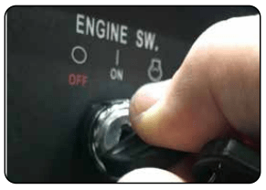
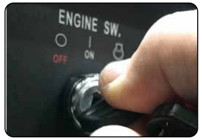
4. Turn engine switch to START
The key switch is located on the left side of the front power panel. Insert the key and turn to the start position to start the generator. Allow the key to return to the run position once started.
5. Turn engine switch to ON
When the engine starts, allow the engine switch to return to the ON position.
6. Open choke
Push the choke to the OPEN position as the engine warms up.
CAUTION: LPG must be shut off when using gasoline!
CAUTION: Gasoline must be shut off when using LPG!
CAUTION: Disconnect all electrical loads from the generator before attempting to start!
WARNING: Operating the starter motor for more than 5 seconds can damage the motor. If the engine fails to start, release the switch and wait 10 seconds before operating the starter again.
Starting the Generator Using Recoil Start
1. Shut breaker off
The breaker is located on the right side of the front power panel. Flip the breaker down to prevent accidental load when starting the generator.
2. Turn gas valve on
The gas valve is located above the recoil start on the bottom of the fuel tank. Rotate the valve clockwise to the vertical position to turn on the gas supply.
3. Close choke
The choke lever is located above the air filter to the right of the recoil start. Slide the lever to the left to cut the air supply and allow more gas into the engine to start.
4. Turn engine switch to On
The key switch is located on the left side of the front power panel. Insert the key and turn to the on position to start the generator.
5. Close choke
The choke lever is located above the air filter to the right of the recoil start. Slide the lever to the left to cut the air supply and allow more gas into the engine to start.
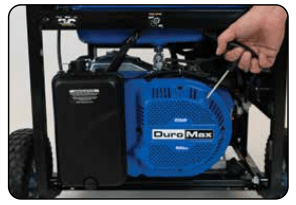
6. Pull the recoil start
The recoil start is located on the left side panel next to the air filter. Pull the recoil handle slowly until resistance is felt, then quickly pull the recoil handle until fully extended.
CAUTION: Release the recoil handle only after the cord has retracted. Releasing the recoil handle while extended may cause harm to yourself or your equipment.
7. Open choke
8. Turn breaker ON / Connect
The breaker is located on the right side of the front power panel. Flip the breaker up to allow the power to flow to the receptacles. Connect your devices to the receptacles on the front panel. Start with the largest loads first.
USING THE GENERATOR
AC Usage
You may connect electrical devices running on AC current according to their wattage requirements.
The chart below shows the rated and surge wattage of your generator according to its model number.
The rated wattage corresponds to the maximum wattage the generator can output on a continuous basis.
The surge wattage corresponds to the maximum amount of power the generator can output for a short period of time. Many electrical devices such as refrigerators require short bursts of extra power, in addition the rated wattage listed by the device, to stop and start their motors. The surge wattage ability of the generator covers this extra power requirement.
The total running wattage requirement of the electrical devices connected to the generator should not exceed the rated wattage of the generator itself. To calculate the total wattage requirement of the electrical devices you wish to connect, find the rated (or running) wattage of each device. This number should be listed somewhere on the device or in its instruction manual.
If you cannot find this wattage, you may calculate it by multiplying the Voltage requirement by the Amperage drawn: Watts = Volts x Amps. If these specifications are not available you may estimate the Watts required by your device by using the chart on the next page.
Once you have found the rated wattage requirement of each electrical device, add these numbers to find the total rated wattage you wish to draw from the generator. If this number exceeds the rated wattage of the generator, DO NOT connect all these devices. Select a combination of electrical devices, which has a total rated wattage lower than or equal to the rated wattage of the generator.
Connecting a load to the generator
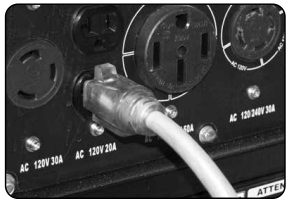
NOTE: Be sure to attach devices to the correct receptacle (outlet).
● 120v devices can be directly connected to the 120v ONLY receptacles.
● 120v devices can be connected to the 120/240v receptacle using an appropriate adapter.
● 240v devices can ONLY be connected to the 240v receptacle.
CAUTION: Do not connect 50Hz or 3-phase loads to the generator.
1. Plug in devices
Plug in devices to the appropriate receptacle. When using the generator in 120/240v mode, balance the load as closely as possible. Placing more load on one side of the circuit will reduce the breaker trip period.
2. Turn breaker on
Flip the circuit breaker up to the on position to allow power to the receptacles.
3. Turn on connected devices
Start or turn on appliances starting with the biggest loads first.
DC Usage
CAUTION: The DC receptacle is for recharging 12 Volt automotive-type batteries only. Do not connect any other device to this receptacle.
CAUTION: Never try to jump start a car with your generator.
1. Connect the battery
Connect one charging wire to the positive terminal on the battery and the other charging wire to the negative terminal on the battery.
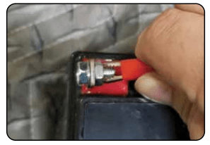
2. Connect positive receptacle
Connect the free end of the positive wire to the positive receptacle (outlet) on the generator.
3. Start Generator
The start switch is located on the left side of the front power panel. Push to the start position to start the generator. Allow the switch to return to the run position once started.
4. Connect negative receptacle
Carefully connect the free end of the negative wire to the negative receptacle on the generator.
5. Disconnecting
When disconnecting, always disconnect the wires from the generator first to avoid a spark.
DANGER - Stored batteries emit highly explosive hydrogen gas when charged. Batteries also contain acid, which can cause severe chemical burns.
DANGER - Do not allow open flames or cigarettes nearby for several minutes after charging a battery.
DANGER - Always wear protective goggles and rubber gloves when charging a battery.
DANGER - If battery acid gets on your skin, flush with water. If battery acid gets in your eyes, flush with water and call a physician immediately.
DANGER - If battery acid is swallowed, drink large quantities of milk and call a Physician immediately.
MAINTENANCE AND CARE
Proper routine maintenance of your generator is essential for safe, economical, and trouble-free operation. It will also help reduce air pollution.
WARNING: Improper maintenance, or failure to correct a problem before operation, can cause a malfunction in which you can be seriously injured or killed. Always follow the inspection, maintenance recommendations, and schedules in this instruction manual.
● Make sure the engine is off before you begin any maintenance or repairs.
● Let the engine and exhaust system cool before touching.
● To reduce the possibility of fire or explosion, be careful when working around gasoline. Use only a nonflammable solvent, not gasoline, to clean parts. Keep cigarettes, sparks, and flames away from all fuel-related parts.
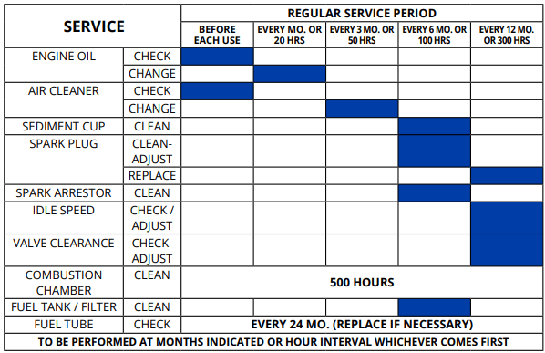
Maintenance Schedule
Remember that this schedule is based on the assumption that your machine will be used for its designed purpose. Sustained high-load, high-temperature operation, or use in unusually wet or dusty conditions, will require more frequent service.
Checking the oil
Check the oil
The generator is equipped with an automatic shutoff to protect it from damage due to low oil. Nonetheless, you should check the oil level of the engine before each use to ensure that the engine crankcase has a sufficient amount.
To check the oil level:
a. Make sure the generator is on a level surface.
b. Unscrew the oil filler/dipstick cap.
c. With a dry cloth, wipe the oil off of the stick on the inside of the cap.
d. Insert the dipstick as if you were replacing the cap and then remove it again. There should now be oil on the stick. If there is no oil on the stick, or oil only at the very end of the stick, you should add oil until the engine crankcase is filled (see “Adding Oil” portion of the “Maintenance” section).
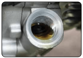
e. The oil will be visible in the oil fill spout when full.
f. Be sure to replace the cap when finished checking oil.
Changing the oil
Worn out or dirty oil does not cool the generator properly and can lead to catastrophic engine damage.
In addition to regular oil changes, it is necessary to drain the oil from the crankcase if it has become contaminated with water or dirt.
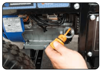
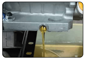
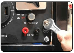
1. Remove drain plug
Using a 12 mm hex wrench, unscrew the oil drain plug, which is located on the crankcase underneath the oil filler/dipstick cap.
Allow all the oil to drain from the generator.
2. Drain oil
Drain oil into an approved oil disposal container. Contact your local auto parts store for information on oil disposal.
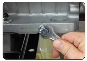
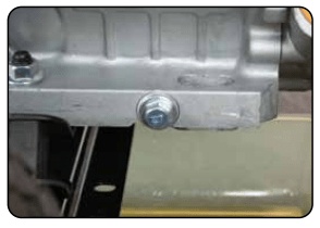
3. Replace drain plug
Replace the oil drain plug and tighten with a 12 mm hex wrench.
Cleaning the air filter
Routine maintenance of the air cleaner helps maintain proper airflow to the carburetor. Check that the air cleaner is free of excessive dirt after every use.
Note: Improper maintenance may cause less air to enter the engine or dirty air to enter the engine causing overheating and engine wear.
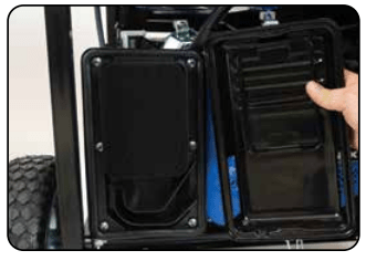
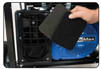
1. Remove the filter cover
Release the clips on the top and bottom of the cover and remove the filter cover.
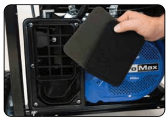
2. Remove filter
Remove the sponge-like elements from the casing.
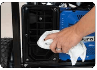
3. Clean out filter casing
Wipe the dirt from inside the empty air cleaner casing.
4. Wash cleaner element
Wash the sponge-like elements in household dish detergent and warm water.
5. Dry cleaner element
Pat dry on a dry cloth and allow the elements to dry completely.
6. Add engine oil to elements
Soak the dry elements in a small amount of engine oil. Ring out any excess oil.
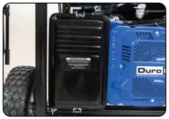
7. Replace elements in casing
Replace the sponge-like elements in the air cleaner casing and replace the cover.
Spark Plug Maintenance
The spark plug is important for proper engine operation. A good spark plug should be intact, free of deposits, and properly gapped.
Improper maintenance may cause reduced fuel economy, misfires, trouble starting, or damage to the spark plug threads.
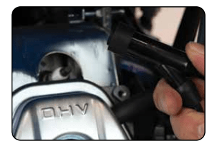
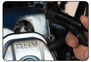
1. Remove spark plug cap
Pull on the spark plug cap to remove it.
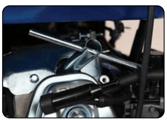
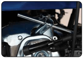
2. Remove spark plug
Unscrew the spark plug from the generator using the spark plug wrench included with this product.
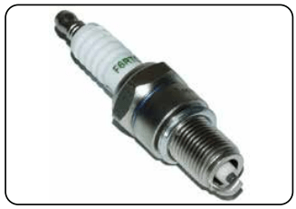
3. Inspect spark plug
Visually inspect the spark plug. If it is cracked or chipped, discard and replace it with a new spark plug. We recommend using an F6RTC spark plug such as NGK BPR6ES.
4. Measure plug gap
Measure the plug gap with a gauge. The gap should be 0.7-0.8 mm (0.028-0.031 in).
5. Clean and re-gap
If you are re-using the spark plug, use a wire brush to clean any dirt from around the spark plug base and then re-gap the spark plug.
6. Install spark plug
Screw the spark plug back into its place on the generator using the spark plug wrench.
7. Replace spark plug cap
Replace the spark plug cap.
TROUBLESHOOTING
Mode
Description
Engine will not start
Engine Switch is “Off”
Set engine switch to “run”
Fuel Valve is “Closed”
Turn fuel valve to “open”
Choke is open
Close the choke
Engine is out of fuel
Add fuel
Fuel is old or contaminated
Change fuel
Spark Plug is dirty
Clean spark plug
Spark Plug is broken
Replace spark plug
Generator is not level
Move generator to a level surface
Oil is low.
Add / change oil
Engine runs, but there is no electrical output
Circuit breaker is “Off”
Turn “on” circuit breaker
Wiring connection is bad
Replace extension cord(s)
Device connected to generator is malfunctioning
Disconnect malfunctioning device
Generator runs, but does not support all electrical devices connected
Generator is overloaded
Disconnect 1 or more items to reduce the load
Device connected to generator is bad
Disconnect malfunctioning device
Air Cleaner is dirty.
Clean / replace the air filter
Changing / Inspecting the Carbon Brushes
The carbon brushes in conjunction with the AVR regulates power from the generator. The carbon brushes are wearable parts and should be inspected every 250 running hours.
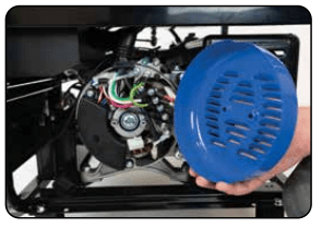
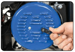
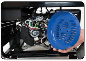
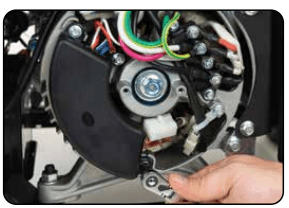
1. Remove generator cover
Remove the 2 bolts of the generator cover then pull the cover off the generator.
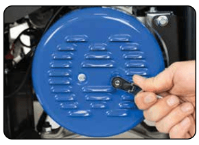
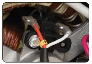
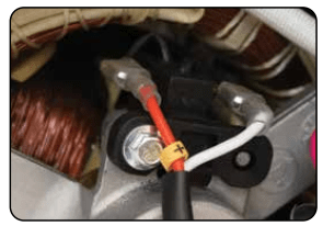
2. Remove bolt from brush
Remove the bolt holding the carbon brush.
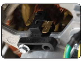
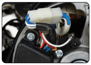
3. Disconnect AVR wires
Remove the two wires from the AVR on the carbon brush
4. Install new brush
Install new carbon brush with bolt.
5. Connect AVR wires
Insert and connect the 2 wires from the AVR, be sure to connect + and – correctly
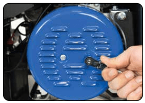
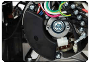
6. Replace generator cover
Replace the back cover of the generator and secure it with the 2 bolts.
Changing / Inspecting the AVR
The carbon brushes in conjunction with the AVR regulates power from the generator. If the generator is overheated or overloaded, the AVR may be damaged and require replacement.
1. Remove generator cover
Remove the 2 bolts of the generator cover then pull the cover off the generator.
2. Remove AVR bolts
Remove the 2 bolts holding the AVR.
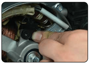
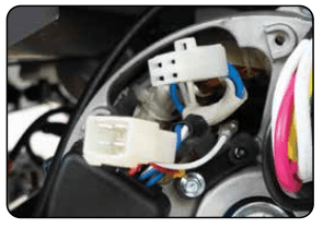
3. Disconnect AVR wire clip
Disconnect the wire clip.
4. Disconnect wires from brush
Remove the 2 wires from the AVR on the carbon brush.
5. Install new AVR
Install the new AVR with the 2 bolts.
6. Reconnect wires to brush
Insert and connect the 2 wires from the AVR, be sure to connect + and – correctly.
7. Reconnect the AVR wire clip
Reconnect the wire clip.
8. Replace generator cover
Replace the back cover of the generator and secure it with the 2 bolts.


 Note: Shipping braces can be thrown away. They will not be needed again.


 WARNING: DO NOT overfill the crankcase. This may damage the motor and shorten the overall life of your generator.
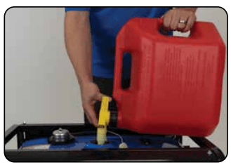
 CAUTION: LPG must be shut off when using gasoline!
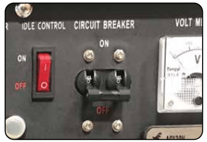
 CAUTION: Release the recoil handle only after the cord has retracted. Releasing the recoil handle while extended may cause harm to yourself or your equipment.
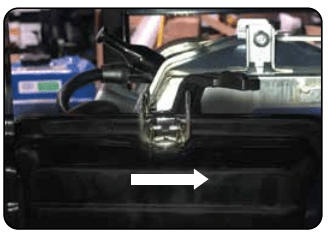


 DANGER - Stored batteries emit highly explosive hydrogen gas when charged. Batteries also contain acid, which can cause severe chemical burns.
 WARNING: Improper maintenance, or failure to correct a problem before operation, can cause a malfunction in which you can be seriously injured or killed. Always follow the inspection, maintenance recommendations, and schedules in this instruction manual.