Loading ...
Loading ...
Loading ...
Version 02/12 - Page 8
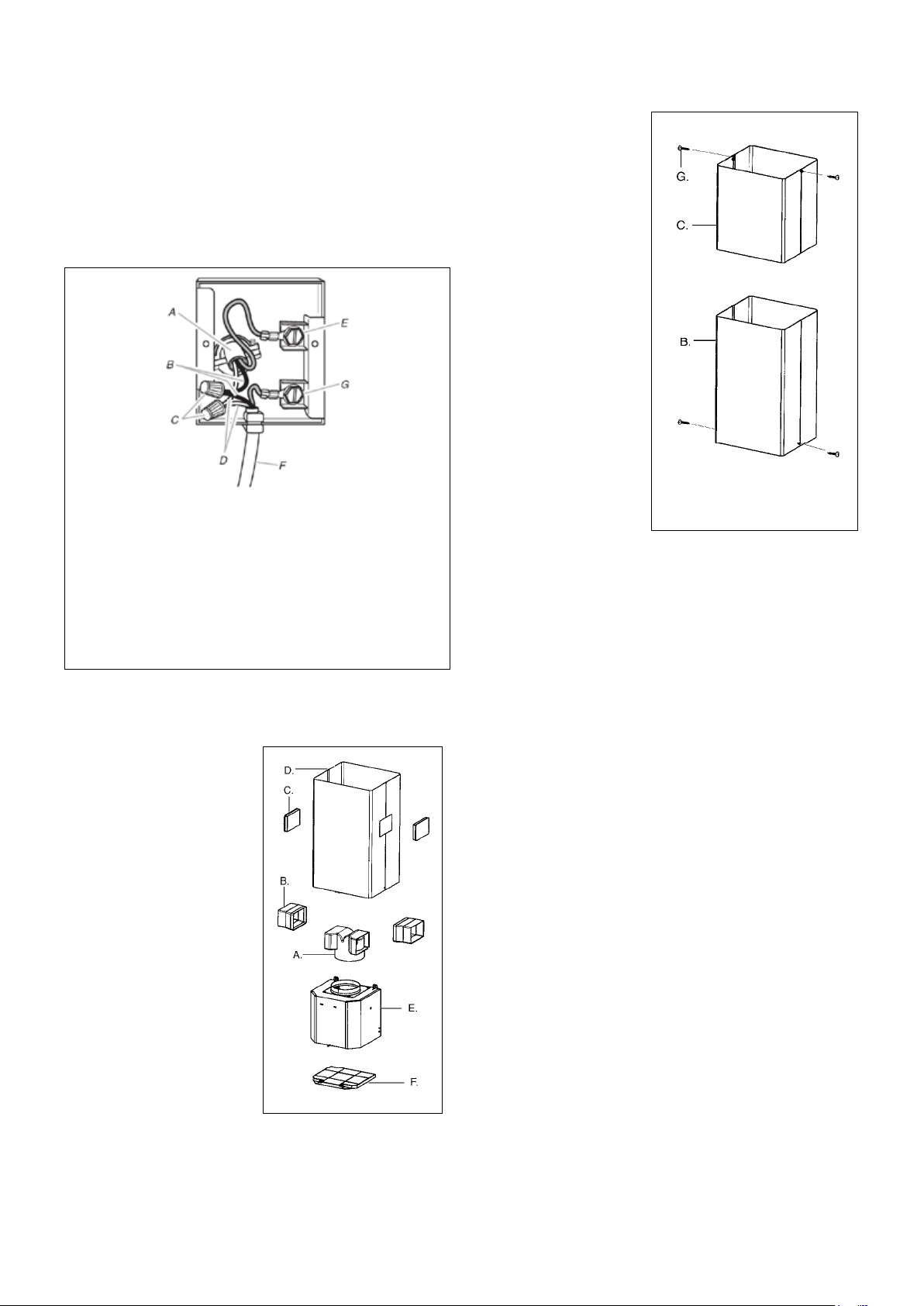
FIGURE 13
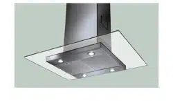
MAKE THE ELECTRICAL CONNECTION
(SEE
FIGURE 11) DO NOT turn on the power until installation is
complete!
Green grounding screw. Attach the White lead of the power
supply to the White lead of the rangehood with a twist-on type
connector.
1.
(C in FIGURE 13)
attaches to the top of the
support structure using two
screws provided (G in FIGURE
13). If using the High Ceiling
Chimney Kit
with the kit. Slide up and
2. Attach the duct work to the
DAMPER (M in FIGURE 1).
duct tape to prevent leaks.
3.
(B in FIGURE 13)
attaches using two screws
provided (G in FIGURE 13).
(B in FIGURE 12) with the holes
(D in FIGURE 12) and snap
in the VENT GRIDS (C in FIGURE 12).
INSTALLING THE RANGEHOOD
A. Home power supply cable
D.White wires
E. Green (or bare) ground wire from home power supply
connected to green ground screw
F. Range hood power supply cable
G.Range hood power supply cable connected to green
ground screw
FIGURE 11
Ductless installations require
a Ductless Conversion
Kit whose components are
pictured in FIGURE 12. Do
not use the DAMPER (M
in FIGURE 1) for ductless
installations. The LOWER
(B
in FIGURE 1) should be
discarded and replaced by
the new one with holes from
the Ductless Conversion Kit
(D in FIGURE 12).
As indicated in FIGURE
12
DIVERTER (A) over the
(E)
(B) into the
DIVERTER (A).
FIGURE 12
FOR DUCTLESS INSTALLATIONS
Loading ...
Loading ...
Loading ...