Version 02/12 - Page 1
Glassy Isola
Island Mount Canopy Rangehood
READ AND SAVE THESE INSTRUCTIONS
The Installer must leave these instructions with the homeowner. The
homeowner must keep these instructions for future reference and for
local electrical inspectors' use.
READ THESE INSTRUCTIONS BEFORE YOU START INSTALLING THIS RANGEHOOD
WARNING: - TO REDUCE THE RISK OF A RANGE TOP GREASE FIRE:
a) Never leave surface units unattended at high settings. Boilovers cause smoking and greasy spillovers that may ignite.
Heat oils slowly on low or medium setting.
b) Always turn hood ON when cooking at high heat or when ambeing food
(i.e. Crepes Suzette, Cherries Jubilee, Peppercorn Beef Flambé).
c) Clean ventilating fans frequently. Grease should not be allowed to accumulate on fan or lter.
d) Use proper pan size. Always use cookware appropriate for the size of the surface element.
WARNING: - TO REDUCE THE RISK OF INJURY TO PERSONS IN THE EVENT OF A RANGE TOP GREASE FIRE, OBSERVE
THE FOLLOWING (*):
a) SMOTHER FLAMES with a close-tting lid, cookie sheet, or metal tray, then turn off the burner. BE CAREFUL TO PRE-
VENT BURNS. If the ames do not go out immediately EVACUATE AND CALL THE FIRE DEPARTMENT.
b) NEVER PICK UP A FLAMING PAN - You may be burned.
c) DO NOT USE WATER, including wet dishcloths or towels - a violent steam explosion will result.
d) Use an extinguisher ONLY if:
1) You know you have a Class ABC extinguisher, and you already know how to operate it.
2) The re is small and contained in the area where it started.
3) The re department is being called.
4) You can ght the re with your back to an exit.
(*) Based on “Kitchen Firesafety Tips” published by NFPA.
This rangehood requires at least 24" of clearance between the bottom of the rangehood and the cooking surface or countertop.
This minimum clearance may be higher depending on local building code. For example, for gas ranges, a minimum of 30" is
recommened and may be required. Overhead cabinets on both sides of this unit must be a minimum of 18" above the cooking
cutouts.
LISEZ BIEN CETTE FICHE AVANT D'INSTALLER LA HOTTE
AVERTISSEMENT - POUR MINIMISER LE RISQUE D’UN FEU DE GRAISSE SUR LA TABLE DE CUISSON : a) Ne jamais laisser
un élément de la table de cuisson fonctionner sans surveillance à la puissance de chauffage maximale; un renversement/
débordement de matière graisseuse pourrait provoquer une inammation et le génération de fumée. Utiliser toujours une
puissance de chauffage moyenne ou basse pour le chauffage d’huile. b) Veiller à toujours faire fonctionner le ventilateur
de la hotte lors d’une cuisson avec une puissance de chauffage élevée ou lors de la cuisson d’un mets à amber (i.e.
Crepes Suzette, Cherries Jubilee, Peppercorn Beef Flambé). c) Nettoyer fréquemment les ventilateurs d’extraction. Veiller
à ne pas laisser de la graisse s’accumuler sur les surfaces du ventilateur ou des ltres. d) Utiliser toujours un ustensile
de taille appropriée. Utiliser toujours un ustensile de taille adapté à la taille de l’élément chauffant.
AVERTISSEMENT: - POUR PRÉVENIR LES BLESSURES EN CAS DE FEU SUIVRE LES RECOMMANDATIONS SUIVANTES
(*): a) ÉTOUFFEZ LE FEU avec un couvercle métallique et fermez le brûleur. Si le feu ne s'éteint pas tout de suite, QUIT-
TEZ LES LIEUX ET APPELEZ LES POMPIERS. b) NE TOUCHEZ JAMAIS UNE CASSEROLE EN FLAMMES. c) N'UTILISEZ
JAMAIS DE L'EAU ou un torchon mouillé pour éteindre le feu - ce qui pourrait causer une explosion de vapeur. d) N'utilisez
un extincteur que si: 1. Vous avez un modèle ABC et vous connaissez bien son mode d'emploi. 2. Le feu est petit et peu
répandu. 3. Les pompiers sont déjà prévenus. 4. Vous avez une sortie derrière vous. (*) Basé sur la "cuisine Firesafety
incline" édité par NFPA.
le code municipal. Par exemple, les cuisinières à gaz peuvent requérir 30 po. de hauteur. Les armoires au-dessus de chaque
armoires.
Version 02/12 - Page 2
VENTING REQUIREMENTS
Determine which venting method is best for your application.
Ductwork can extend either through the wall or the roof.
The length of the ductwork and the number of elbows should
size of the ductwork should be uniform. Do not install two
around the cap.
Flexible ductwork is not recommended. If it is used,
each foot of exible ductwork used is equivalent to
two feet of straight metal ductwork when calculating
the ductrun length. Thus, a exible elbow equals two
standard elbows.
cut, then a supporting frame must be constructed.
TO PAGE 4.
WARNING - To Reduce The Risk Of Fire, Use Only Metal
Ductwork.
ELECTRICAL REQUIREMENTS
separate 15 amp fused circuit. A time-delay fuse or circuit
breaker is recommended. The fuse must be sized per local
codes in accordance with the electrical rating of this unit as
must conform to the requirements of the National Electrical
ordinances. Wire size and connections must conform with the
may be obtained from:
National Fire Protection Association
Quincy, Massachusetts 02269
home.
other enclosed space.
ventilation air.
This appliance should be connected directly to the fused
nonmetallic sheathed copper cable. Allow some slack in the
cable so the appliance can be moved if servicing is ever nec-
at each end of the power supply cable (at the appliance and at
When making the electrical connection, cut a 1 1/4" hole in the
wall. A hole cut through wood must be sanded until smooth. A
hole through metal must have a grommet.
WARNING - TO REDUCE THE RISK OF FIRE OR ELECTRIC
SHOCK, do not use this fan with any solid-state speed
control device.
WARNING - TO REDUCE THE RISK OF FIRE, ELECTRICAL
SHOCK, OR INJURY TO PERSONS, OBSERVE THE
FOLLOWING:
manufacturer. If you have any questions, contact the
manufacturer.
at service panel and lock the service disconnecting means to
prevent power from being switched on accidentally. When the
service disconnecting means cannot be locked, securely fasten a
prominent warning device, such as a tag, to the service panel.
CAUTION: For General Ventilating Use Only. Do Not Use To
Exhaust Hazardous or Explosive Materials and Vapors.
WARNING - TO REDUCE THE RISK OF FIRE, ELECTRICAL
SHOCK, OR INJURY TO PERSONS, OBSERVE THE
FOLLOWING:
prevent backdrafting. Follow the heating equipment
manufacturer's guideline and safety standards such as those
published by the National Fire Protection Association (NFPA),
and the American Society for Heating, Refrigeration and Air
-
ties.
electrical wiring and other hidden utilities.
D) Ducted fans must always be vented to the outdoors.
WARNING
nonmetallic gaskets or other materials, DO NOT
use for grounding.
circuit. A fuse in the neutral or grounding circuit
could result in electrical shock.
as to whether the rangehood is properly grounded.
WARNING
For residential use only.
!
!
Cold Weather installations
An additional back draft damper should be installed to minimize
installed to minimize conduction of outside temperatures as part of
the vent system. The damper should be on the cold air side of the
thermal break. The break should be
as close as possible to where the
vent system enters the heated portion of the house.
CAUTION: To reduce risk of re and to properly exhaust air, be
sure to duct air outside - do not vent exhuast air into spaces within
walls or ceilings or into attics, crawl spaces or garages.
Version 02/12 - Page 3
RÈGLEMENTS D'ÉVACUATION
le toit.
métallique à l'intérieur et scellez bien le clapet extérieur avec
du calfeutrage.
Utilisez un tuyau d'évacuation rigide lorsque possible.
Un tuyau exible égale deux fois plus qu'un tuyau rigide,
ce qui réduit la puissance d'évacuation.
Veillez à ce que l'espace pour le tuyau soit ample - ainsi on
n'aurait pas besoin de découper les supports de mur intérieur.
Si ce découpage est nécessaire, veillez bien à ce qu'un
renforcement soit mis en place.
Pour de meilleurs résultats, utilisez un tuyau de transition de
9 pouces dès que possible.
AVERTISSEMENT - Pour Ne Pas Risquer Un Feu, Utilisez
Seulement Les Matériaux Métalliques.
Veillez a ce qu'un contact d'un demi-pouce (1/2 po.) soit
boite à fusible).
Faites un trou de 1 1/4 po. dans le mur. S'il s'agit d'un trou en
bois - sablez-le bien, tandis qu'un trou passant par le métal
demande un bouche-trou.
AVERTISSEMENT - POUR RÉDUIRE LE RISQUE
D'INCENDIE OU DE CHOC ELECTRIQUE, ne pas utiliser
ce ventilateur en conjonction avec un dispositif de réglage
de vitesse à semi-conducteurs.
AVERTISSEMENT – POUR MINIMISER LES RISQUES
D’INCENDIE, CHOC ÉLECTRIQUE OU DOMMAGES
CORPORELS, OBSERVER LES PRESCRIPTIONS
SUIVANTES: Suivez les recommandations du fabricant
et entre en communication avec lui pour toute
information.
Fermez le courant avant tout entretien et veillez a ce qu'il
reste fermé. Si on ne peut pas verrouiller le panneaux
du service électrique, afchez un avis de danger sur la
porte.
AVIS: Pour L'évacuation Générale - Veillez à Ne Pas
Evacuer Des Matériaux Ou Vapeurs Explosif.
AVERTISSEMENT – POUR MINIMISER LES RISQUES
D’INCENDIE, CHOC ÉLECTRIQUE OU DOMMAGES
CORPORELS, OBSERVER LES PRESCRIPTIONS
SUIVANTES: L'installation Et Le Raccordement Electrique
Doivent Se Faire Par Un Technicien Qualié Selon Tous
Les Codes Municipaux.
An d'obtenir un rendement maximal en ce qui a trait à la
combustion ainsi qu'à l'évacuation des gaz par la conduite
de cheminée, une bonne aération est nécessaire pour
tous les appareils à combustion. Suivez les conseils et
mesures de sécurité du fournisseur tels que ceux publiés
par l'Association Nationale de la Sauvegarde contre
l'Incendie et l'Association Américaine d'Ingénieurs de
Chauffage, Frigorifaction et Air Climatisé ainsi que les
codes municipaux.
En perçant un mur veillez à ne pas perforer un autre l
électrique.
Une ventilateur à évacuation extérieure doit être
raccordée à l'extérieur.
AVERTISSEMENT
mansarde soit dans un espace enfermé.
occasionner un feu.
FICHE TECHNIQUE ÉLECTRIQUE
Le raccordement électrique doit se faire avec un circuit séparé
de 15 ampères fusible à 120V, 60 Hz, courant alternant. On
recommande un coupe-circuit. La taille du fusible doit se
devra aussi se conformer aux règlements du code national
informations chez:
l'Association Nationale de la Prévention du Feu
Quincy, Massachusetts 02269
Raccordez cet appareil directement au coupe-circuit avec un
métallique ou autre.
mise à terre - ce qui peut causer une secousse
électrique.
soit bien mise à terre.
occasionner un feu.
AVERTISSEMENT
Uniquement pour usage menager.
!
!
Installations pour régions à climat froid
thermique pour minimiser la conduction de chaleur par l'intermédiaire
du conduit d'évacuation, de l'intérieur de la maison à l'extérieur. Le
possible de l'endroit où le système d'évacuation s'introduit dans la
partie chauffée de la maison.
Version 02/12 - Page 4
TOOLS NEEDED FOR INSTALLATION
PARTS SUPPLIED FOR INSTALLATION
PARTS NEEDED FOR INSTALLATION
OPTIONAL ACCESSORIES AVAILABLE
High Ceiling Chimney Kit
Extends the island chimney for high
ceilings
part # HIGH2 - Stainless
*Ductless Conversion Kit
For non-vented installations only
* it is highly recommended that professional
style cooking always be vented to the
outside
Replacement Charcoal Filter
For non-vented installations only,
part # FILTER2
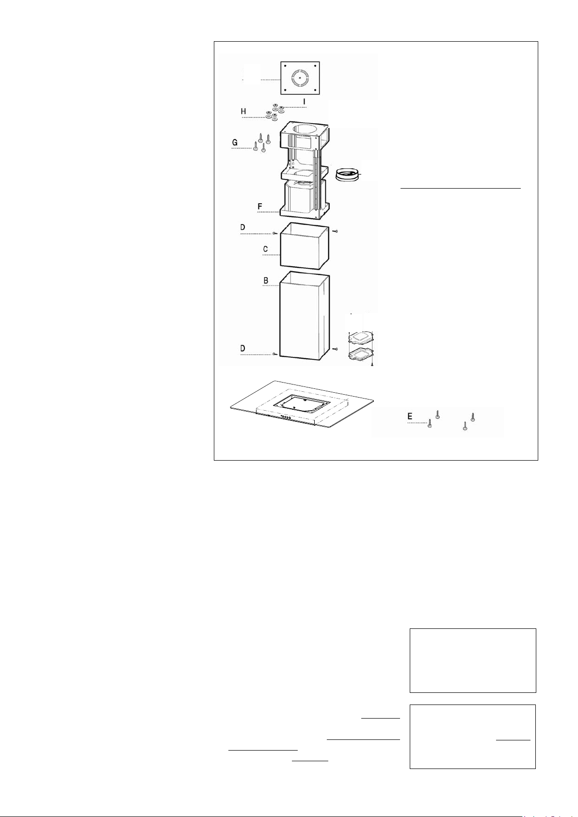
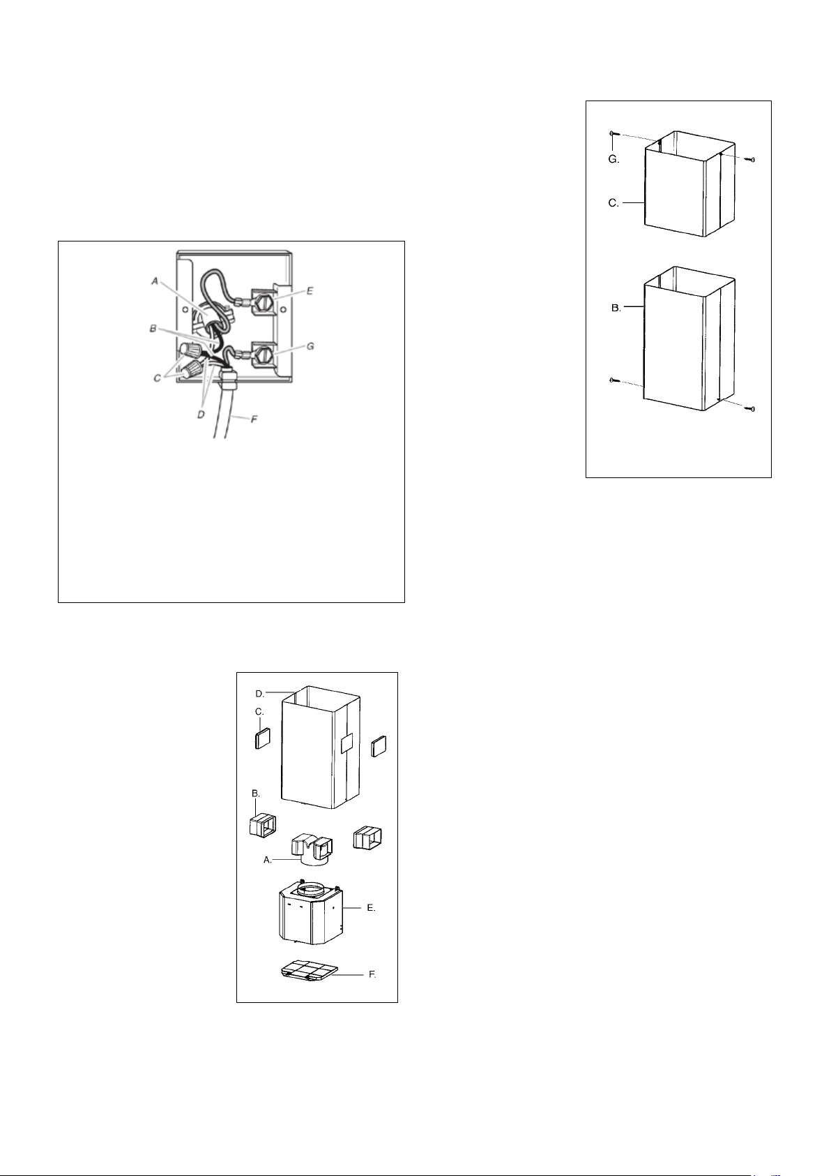
UNPACK THE RANGEHOOD
THIS TIME! This plastic covering protects the chimney from scratches during installation.
For safe packaging, the entire chimney section of the hood is shipped assembled. It must be disassembled completely for
installation. Disassemble packaged chimney components by sliding apart the chimney covers (B and C in FIGURE 1). Remove
(B) (F) by removing the 2 philips screws on the outside bottom
(C) (F) by removing the 2 philips
screws on the outside top of the chimney cover.
CALCULATE THE DUCTRUN LENGTH
The ductrun should not exceed 35 equivalent
feet if ducted with the required minimum of 6"
by adding the equivalent feet in FIGURE 2 for
each piece of duct in the system. An example
is given in FIGURE 3.
For best results, use no more than three 90°
elbows. Make sure that there is a minimum
of 24" of straight duct between elbows if
more than one is used. Do not install two
elbows together. If you must elbow right
away, do it as far away from the hood's
exhaust opening as possible.
9 Feet Straight Duct
Total System
FIGURE 3
3.0 feet
5.0 feet
12.0 feet
0.0 feet
FIGURE 2
9.0 feet
10.0 feet
0.0 feet
19.0 feet
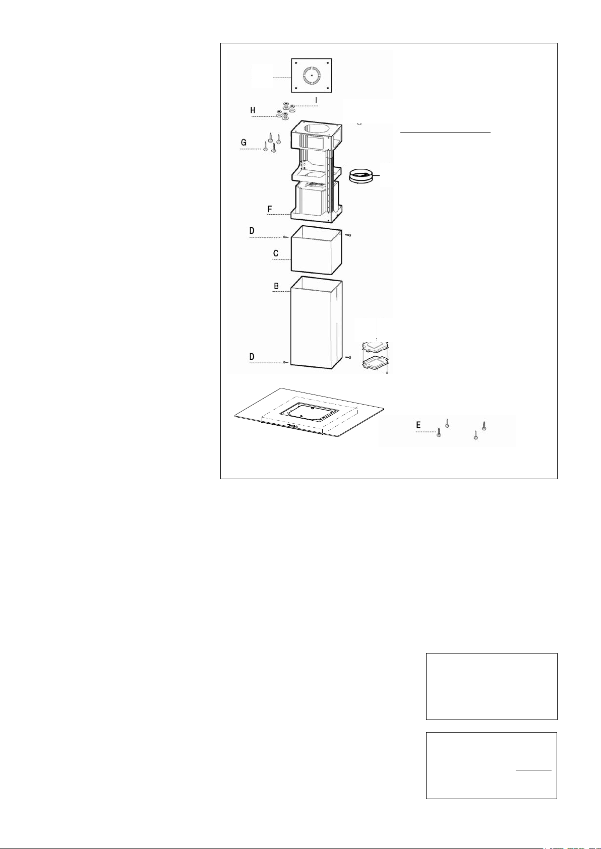
PREPARING TO ATTACH THE CHIMNEY
The rangehood attaches to the ceiling by a
metal support structure (F in FIGURE 1). This
support must be attached to the ceiling before
the canopy is attached. This structure must
FOR WOOD CEILINGS:
wood screws and washers.
FOR PLASTER OR SHEET ROCK CEILINGS:
If possible, the support must be attached to
behind the sheet rock must be built.
FOR WOOD SHELVES: G, H, &
I in FIGURE 1.
FIGURE 1
A.
B.
C.
D.
E.
F.
G.
H. WOOD SHELF WASHERS
I.
J.
K.
L.
M. DAMPER
J
M
K
L
A
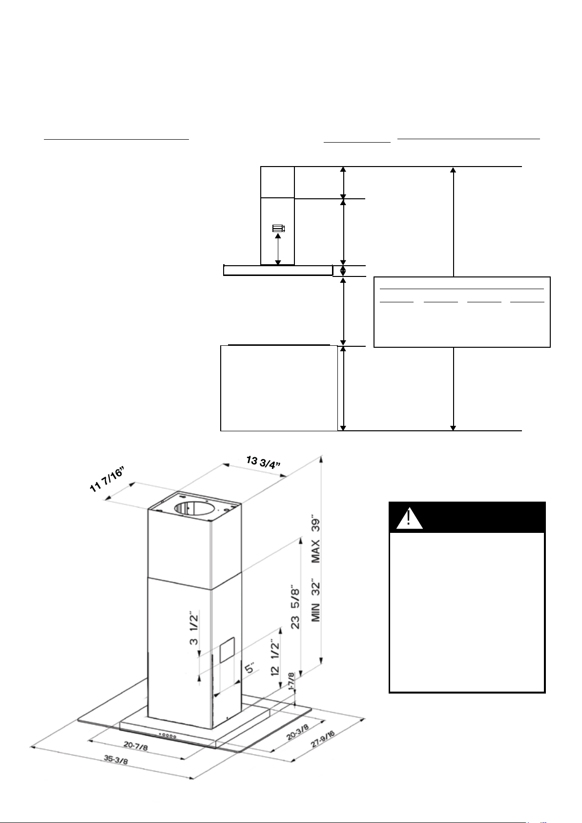
Version 02/12 - Page 5
upper
chimney
cover
lower
chimney
cover
canopy
cabinet base
x = distance from hood to cooktop
(varies depending on installation)
min - 24”, suggested max - 30”
also consult cooktop
manufacturer's recommendation
8 3/8” min
15 3/8” max
23
5/8”
36”
FIGURE 4
DUCTED
DIMENSIONS
x
min & max ceiling height examples
x = 30"
min
8'
max
8'
x = 28"
min
8'
max
8'
x = 26"
min
max
8'
x = 24"
min
max
8'
and designed to meet varying ceiling heights
as indicated in FIGURE 4. The chimney can
between the bottom of the hood and the
cooktop (distance x in FIGURE 4).
For higher ceiling installations, the High
Ceiling Chimney Kit includes an additional
support structure which adds 21" to the
ceiling heights in FIGURE 4.
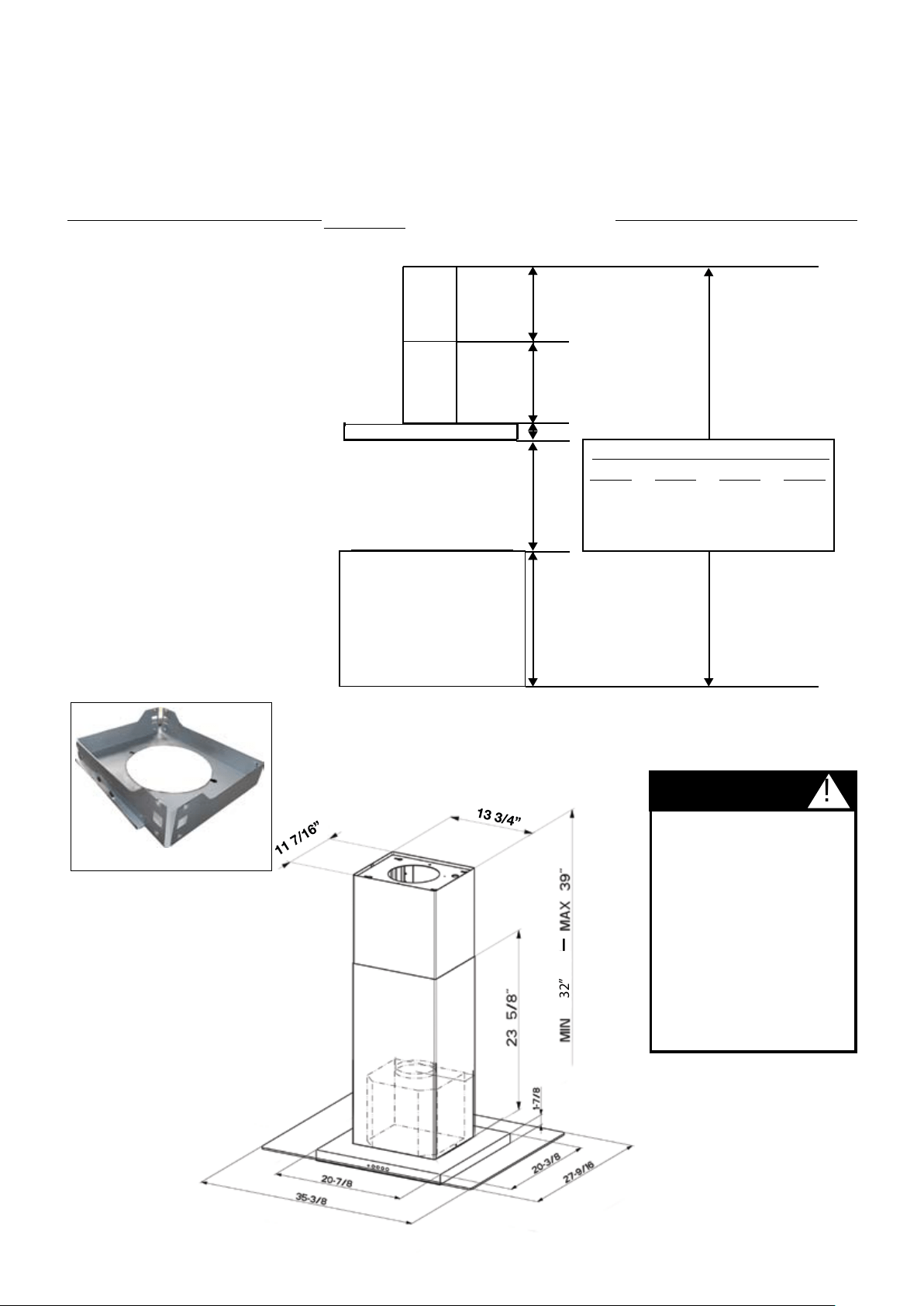
DUCTED INSTALLATION DIMENSIONS
(vented to the outside)
PLAN THE INSTALLATION
This rangehood can be installed as either ducted or ductless. When installed ductless, the rangehood vents out of grates on either
side of the lower chimney. Ductless installations require a Ductless Conversion Kit, available from your dealer.
WARNING!
OF THIS RANGEHOOD, THE
For plaster or sheet rock ceilings,
the support must be attached to
a support structure must be built
behind the plaster or sheet rock.
The manufacturer assumes
damage caused by improper
installations.
32”
FIGURE 5
WARNING
!
NOTE: The chimney structure can reduce
down to a 27" minimum height. To reduce
the height, the middle section of the
support structure (FIGURE 5) needs to
be removed. Out of the box, the minimum
chimney length is 32". Subtract 5" from
all minimum ceiling height calculations
in FIGURE 4 if removing the middle
section. Contact Faber at 508-358-5353
for more information.
Version 02/12 - Page 6
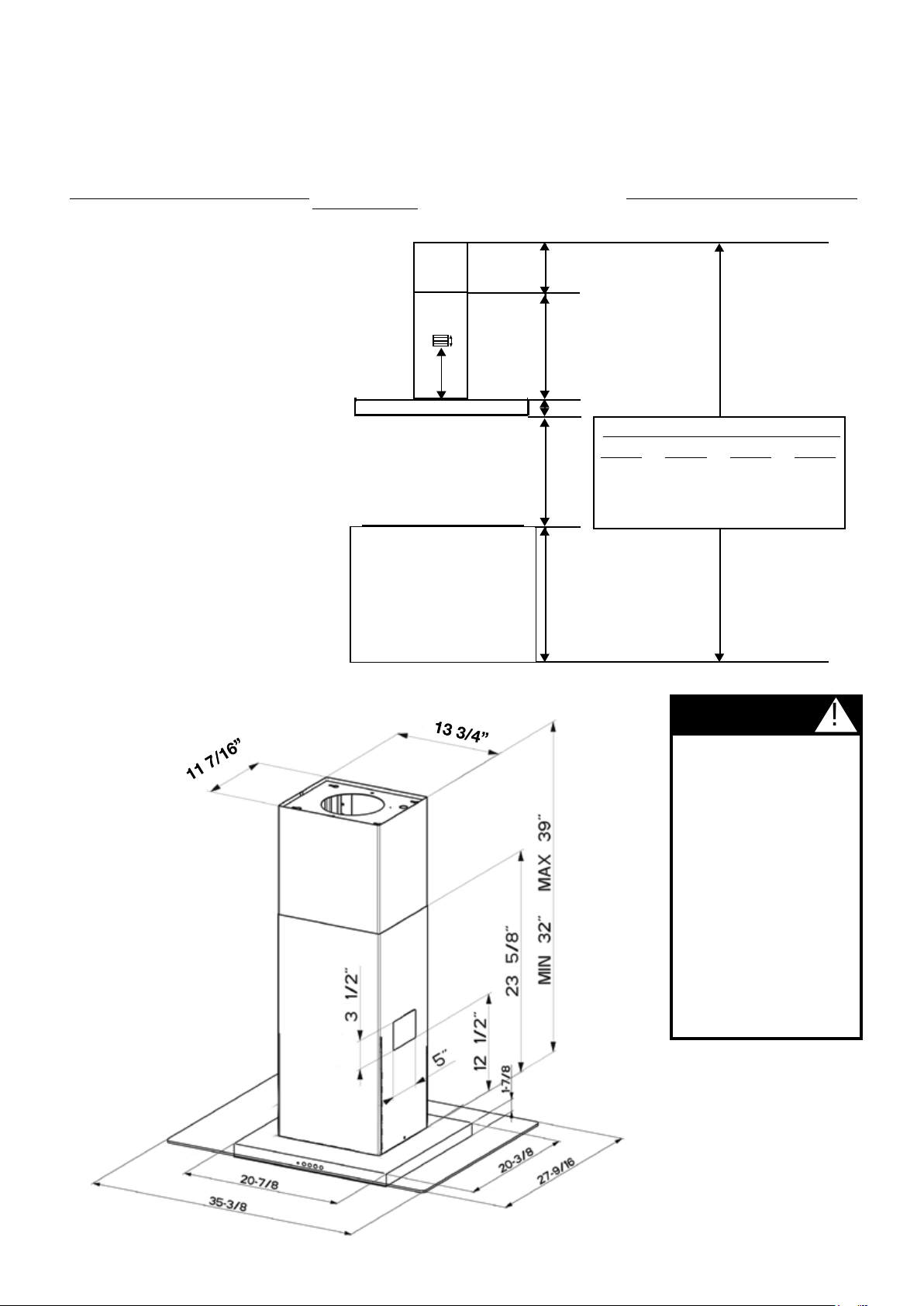
PLAN THE INSTALLATION
This rangehood can be installed as either ducted or ductless. When installed ductless, the rangehood vents out of grates on
either side of the lower chimney. Ductless installations require a Ductless Conversion Kit, available from your dealer.
WARNING!
The ductless Glassy Isola chimney is
indicated in FIGURE 6. The chimney can
between the bottom of the hood and the
cooktop (distance x in FIGURE 6).
For higher ceiling installations, the High
Ceiling Chimney Kit includes an additional
support structure which adds 21" to the
various ceiling heights in FIGURE 6.
upper
chimney
cover
ductless
lower
chimney
cover
canopy
cabinet base
x = distance from hood to cooktop
(varies depending on installation)
min - 24”, suggested max - 30”
also consult cooktop
manufacturer's recommendation
8 3/8” min
15 3/8” max
23
5/8”
36”
FIGURE 6
DUCTLESS
DIMENSIONS
x
min & max ceiling height examples
x = 30"
min
8'
max
8'
x = 28"
min
8'
max
8'
x = 26"
min
max
8'
x = 24"
min
max
8'
DUCTLESS INSTALLATION DIMENSIONS
(not vented to the outside)
12 1/2"
3 1/2”
WARNING
AND WEIGHT OF THIS
RANGEHOOD, THE
or sheet rock ceilings, the
support must be attached
not possible, a support
structure must be built
behind the plaster or sheet
rock. The manufacturer
assumes no responsibility
by improper installations.
!
11 7/16”
13 3/4”
.
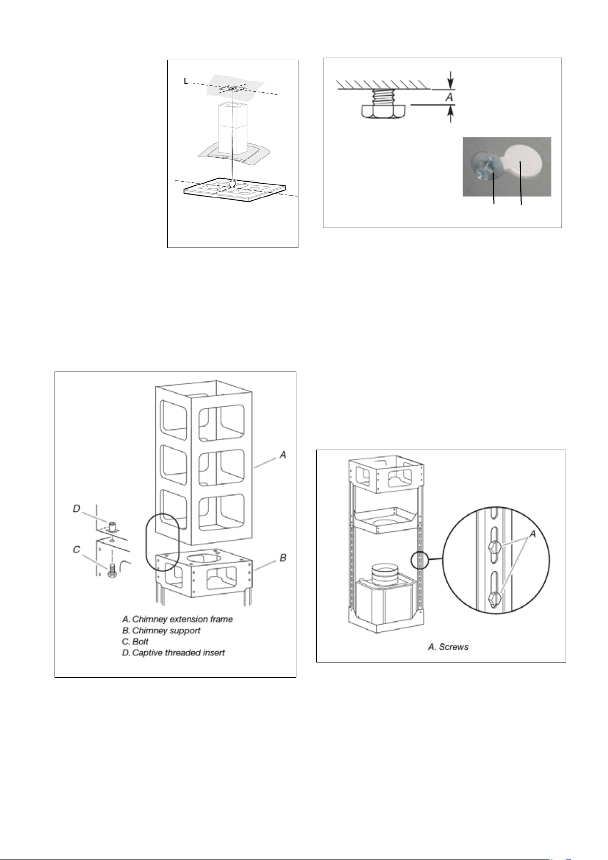
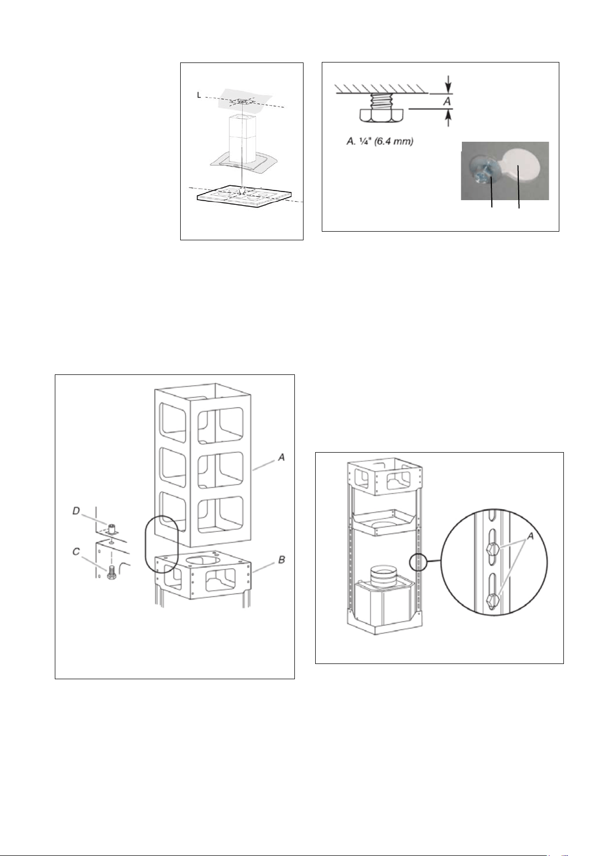
ATTACH THE SUPPORT
4. Determine and make necessary cuts for the ductwork. The duct
opening is shown on the mounting template (L in FIGURE 7). Install
ductwork before mounting the support.
FIGURE 7
1. Put a thick, protective
covering over cooktop,
set-in range or countertop
to protect from damage
or dirt.
2. Determine and clearly
mark with a pencil on the
ceiling where the rangehood
will be installed.
3. A template (L in FIGURE
7) for mounting the support
is supplied in the carton
template to mark holes for
support on the ceiling.
8. Install in previously drilled pilot holes in the ceiling the 4 bolts,
washers and nuts OR the wood screws from the parts bag depending
on your ceiling type (PAGE 4).
(A IN FIGURE 9).
9. Remove wiring box cover located on the top section of the chimney
support.
10.
screws can be tightened after the chimney support is
attached to the ceiling.
11.
through the strain relief.
12. Position the chimney support so that the large end of the
keyhole slots are over the ceiling attachment bolts (B IN FIGURE 9).
Then push the chimney support so that the bolts are in the neck of
the slots. (C IN FIGURE 9) Tighten bolts securely.
IMPORTANT: The chimney support must be securely
attached to the ceiling.
13.
the length of the support by removing the four screws (indicated
in FIGURE 10)
support is determined, install and tighten the four screws.
6.
DO
NOT turn on the power until installation is complete! A knockout
.
7. For ducted installations, place the round DAMPER (N in FIGURE
1) into the exhaust opening of the rangehood and press down.
5. If using the High Ceiling Chimney Kit
(A in FIGURE 8). Position
(B in
FIGURE 8) so that the outside edges and the electrical holes line up.
the 4 bolts (C in FIGURE 8). Tighten bolts securely.
FIGURE 10
FIGURE 8
FIGURE 9
A. 1/4"
B
C
Version 02/12 - Page 8
FIGURE 13
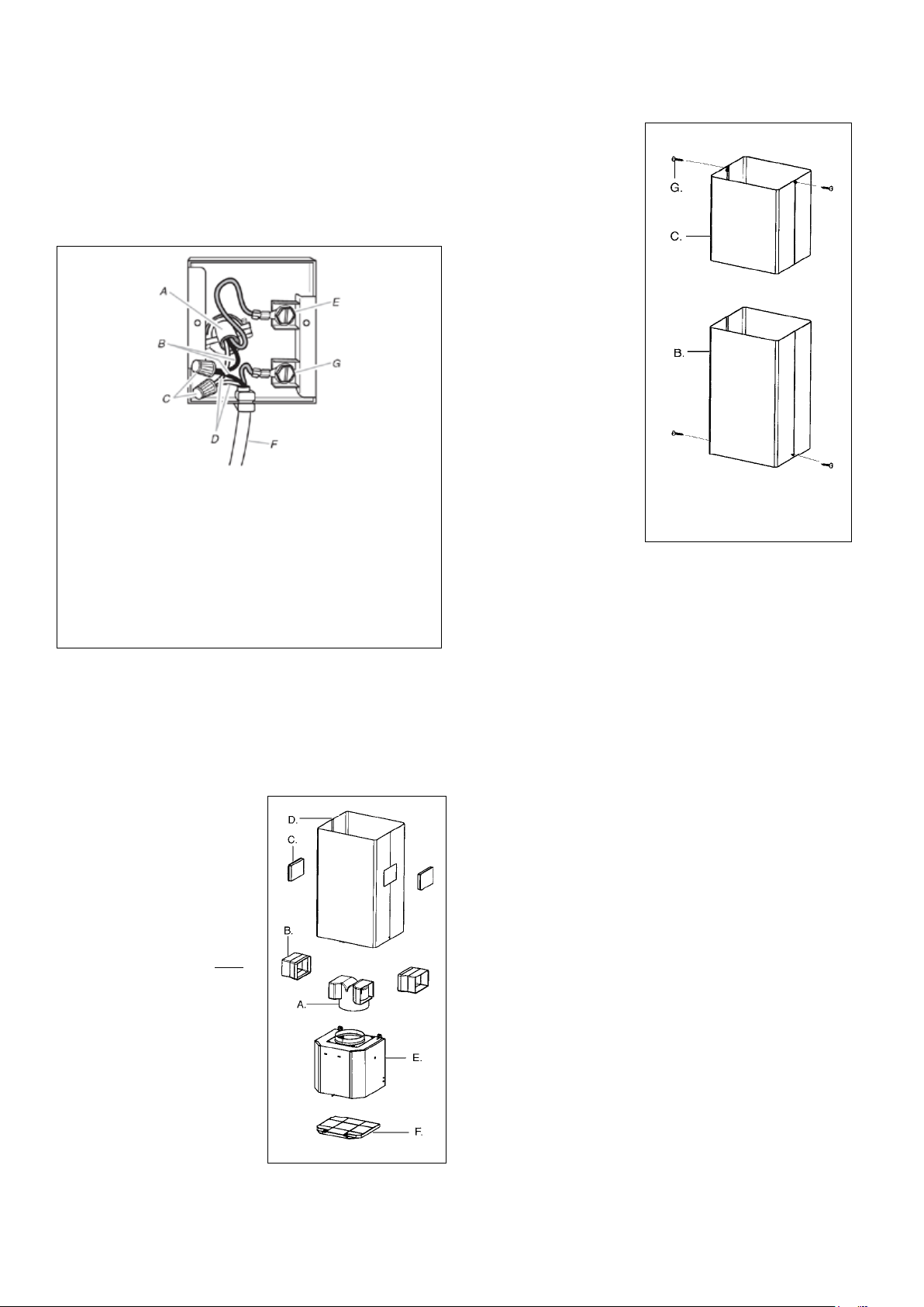
MAKE THE ELECTRICAL CONNECTION
(SEE
FIGURE 11) DO NOT turn on the power until installation is
complete!
Green grounding screw. Attach the White lead of the power
supply to the White lead of the rangehood with a twist-on type
connector.
1.
(C in FIGURE 13)
attaches to the top of the
support structure using two
screws provided (G in FIGURE
13). If using the High Ceiling
Chimney Kit
with the kit. Slide up and
2. Attach the duct work to the
DAMPER (M in FIGURE 1).
duct tape to prevent leaks.
3.
(B in FIGURE 13)
attaches using two screws
provided (G in FIGURE 13).
(B in FIGURE 12) with the holes
(D in FIGURE 12) and snap
in the VENT GRIDS (C in FIGURE 12).
INSTALLING THE RANGEHOOD
A. Home power supply cable
D.White wires
E. Green (or bare) ground wire from home power supply
connected to green ground screw
F. Range hood power supply cable
G.Range hood power supply cable connected to green
ground screw
FIGURE 11
Ductless installations require
a Ductless Conversion
Kit whose components are
pictured in FIGURE 12. Do
not use the DAMPER (M
in FIGURE 1) for ductless
installations. The LOWER
(B
in FIGURE 1) should be
discarded and replaced by
the new one with holes from
the Ductless Conversion Kit
(D in FIGURE 12).
As indicated in FIGURE
12
DIVERTER (A) over the
(E)
(B) into the
DIVERTER (A).
FIGURE 12
FOR DUCTLESS INSTALLATIONS
Version 02/12 - Page 9
(F in
FIGURE 12)
and locking into place. (See FIGURE 17)
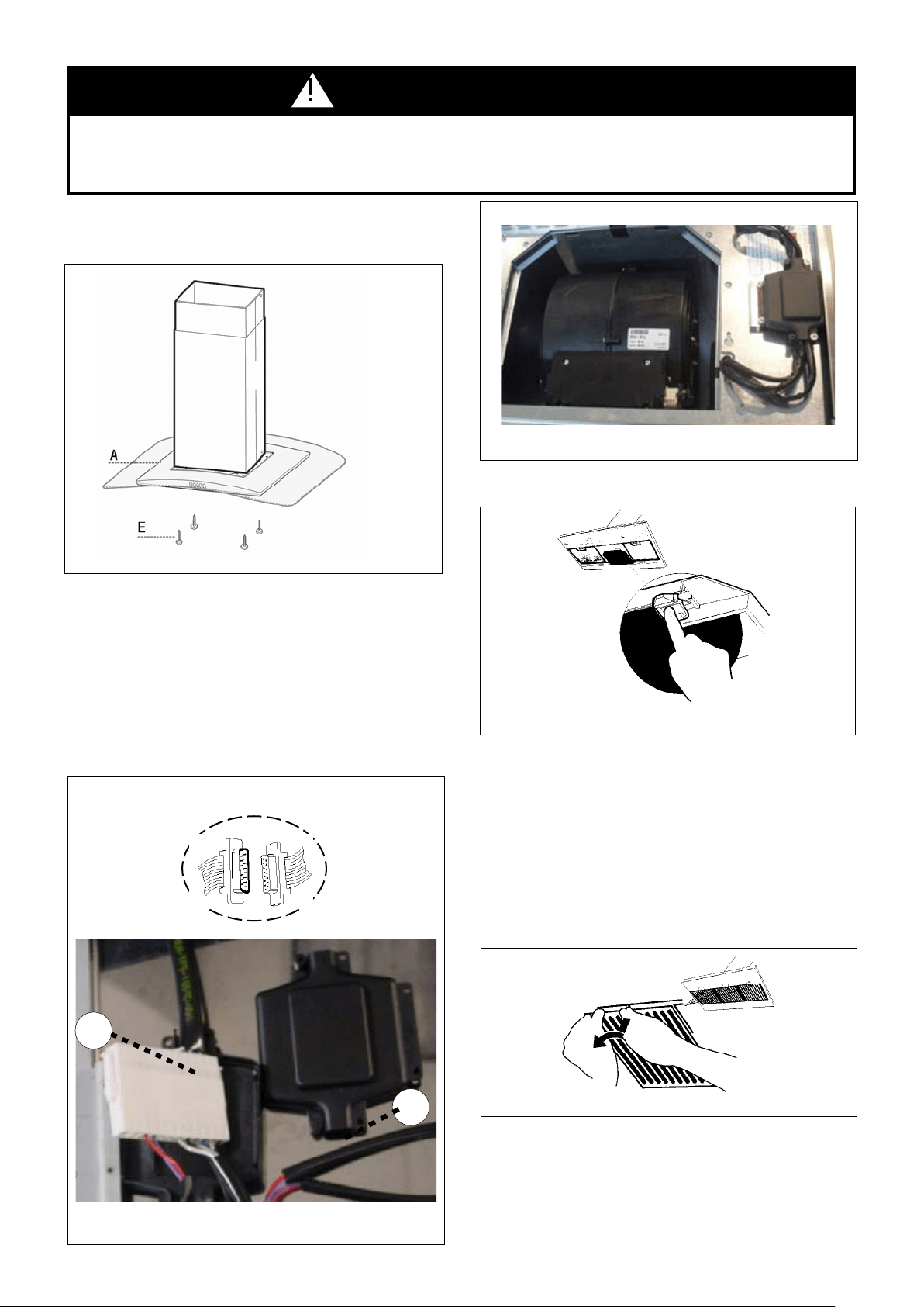
WARNING
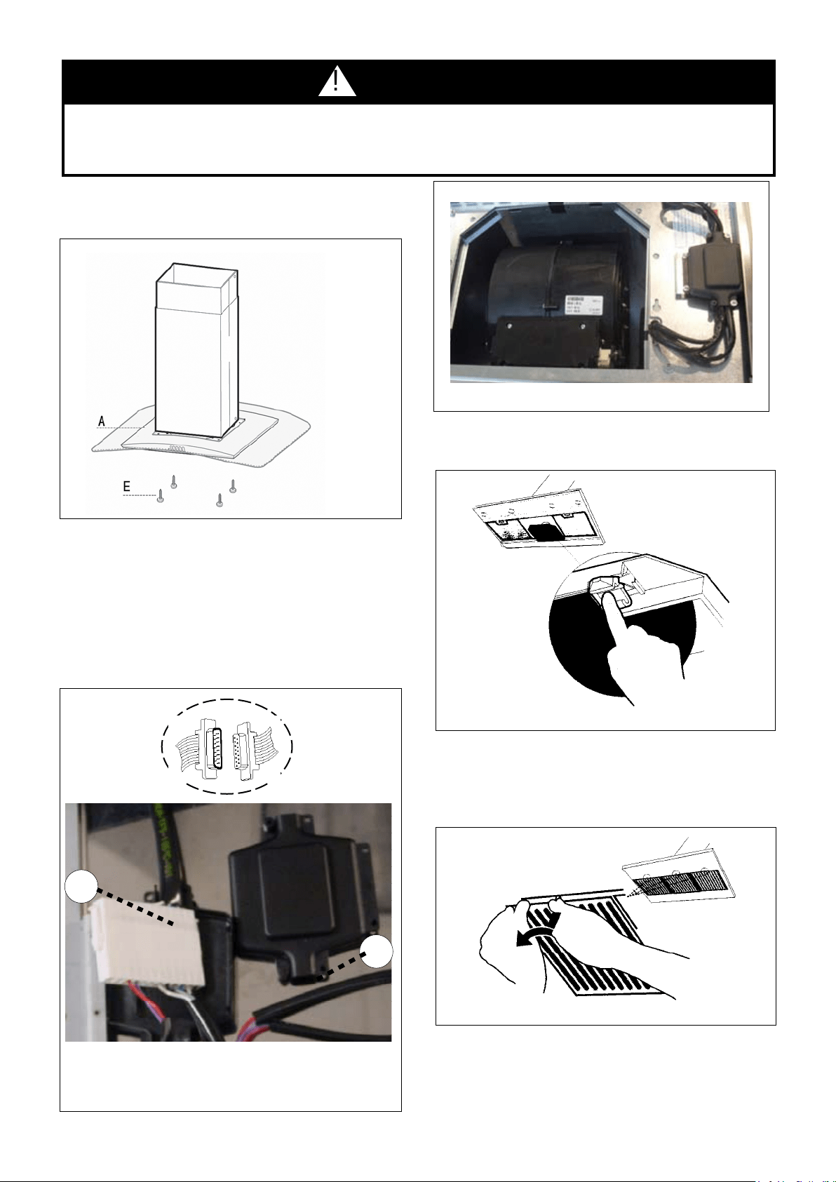
Two people must hold the canopy in place while the third person installs the screws that attach the canopy to the chimney.
4.(A in FIGURE
14) to the assembled chimney support using the four bolts
provided (E in FIGURE 14).
FIGURE 14
FIGURE 17
6.
turning the knob to the left so that the locking lever does not
(as in FIGURE 18). Insert the opposite
FIGURE 18
7. Turn the power supply on. Turn on blower and lights. If the
rangehood does not operate, check that the circuit breaker is
not tripped or the house fuse blown. If the unit still does not
operate, disconnect the power supply and check that the wiring
connections have been made properly.
!
FIGURE 16
MAKE THE INTERNAL ELECTRICAL CONNECTIONS
5. Connect the CONTROL CABLES together as indicated in
A in FIGURE 15. Insert the connected CONTROL CABLES (A
in FIGURE 15) into the black plastic CONNECTOR BOX (B in
FIGURE 15) by connecting the two black plastic pieces using
the four screws provided. (FIGURE 16 for reference also)
FIGURE 15
A
A
B
Version 02/12 - Page 10
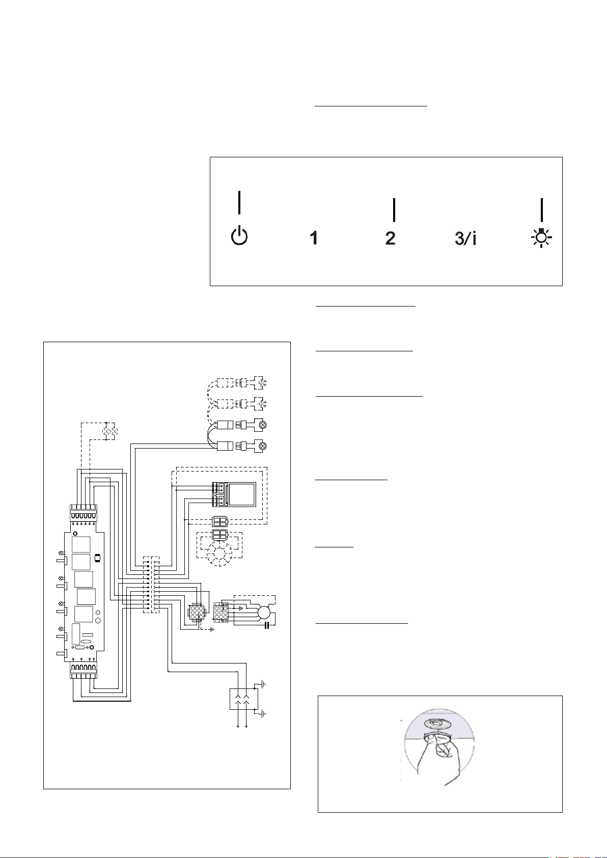
WIRING DIAGRAM
FIGURE 19
USE AND CARE INFORMATION
This rangehood system is designed to remove smoke, cooking
vapors and odors from the cooktop area.
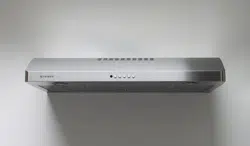
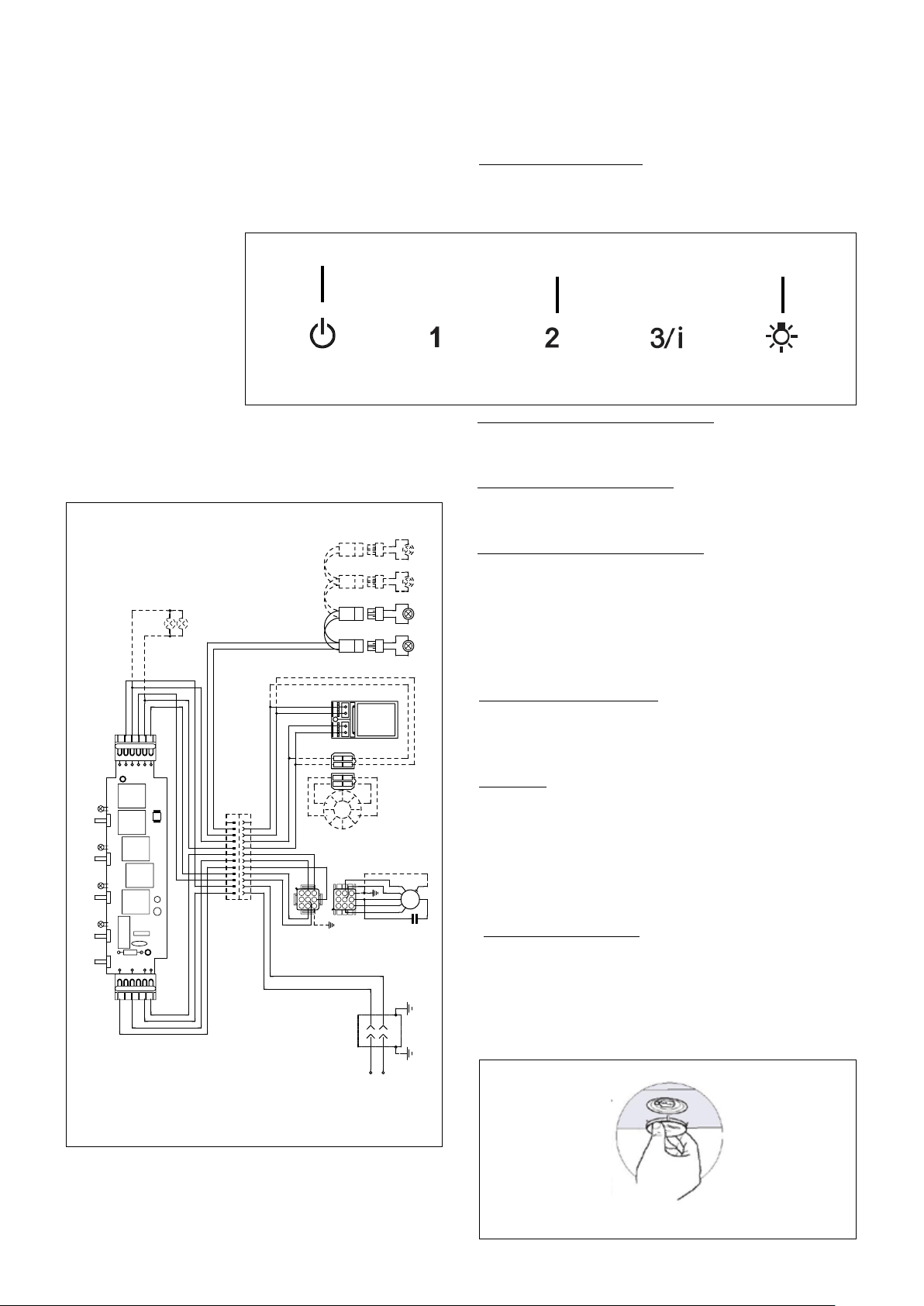
Rangehood Control Panel
The control panel is located on the front edge of the rangehood
canopy. The position and function of each control button are
indicated in FIGURE 19.
For Best Results
Start the rangehood several minutes before cooking to develop
after cooking is complete to clear all smoke and odors from
the kitchen.
Cleaning
hot detergent solution or washed in the dishwasher. Stainless
steel cleaner should be used on stainless rangehoods. Abrasives
Replacing the Lamps
levering it from under the metal ring, supporting it with one hand.
Remove the halogen lamp from the lamp holder by pulling gently.
Replace the lamp with a new one of the same type, making
sure that you insert the two pins properly into the housings on
the lamp holder. Replace the snap-on lamp cover.
FIGURE 20
0 1 2 3 4 5 6 7 8 9
Creato da.
Rev :
Ver :
DOLCE CORRADO
Materiali: non deveno contenere Pb, Cr6+, Hg, PBB, pbde, ai sensi della direttiva 2002/95 CE
SCHEMA ELETTRICO M8-4V ESB FARETTI
Non rilevare quote dal grafico non app ortare modifiche senza l'autorizzazione d'ufficio progettazione
a termini di legge ci riserviamo la propr ieta' del presente disegno con divieto di ripr oduzione totale o parziale
Code :
Disegno N :
Data:
08.Set.2010
LINE IN
120Vac
60Hz ~
L
N
Y-G
WIRING BOX
BLU
RED
BLK
WHT
Y-G
1
2
3
4
5
6
BLK
V1
MC
F
V2
ESB
0
MOTOR
1
MOTOR
BRW
GRY
BLU
123
6 5 4
789
1 2 3
654
987
RED
M8 4V
120V ~
WHT
BRW
2
SPEED
BLU
BLK
1
1
BLK
BLK
WHT
2
2
WHT
ORG
BRW
3
3
BRW
GRY
4
4
GRY
RED
WHT
BLU
Y-G
BLU
5
5
BLU
3/I
SPEED
RED
6
6
RED
WHT
7
7
WHT
VLT(ORG)
8
8
VLT(ORG)
RED(ORG)
9
9
RED(ORG)
RED
10
10
RED
VLT
11
11
VLT
0-1
LIGHT
12
12
TOROIDAL
TRANSFORMER
WHT
4
3
BLK
RED
2
1
BLK
N
L
V4
L
V3
ORG
2
1
RED
ORG
4
3
VLT
WHT
1
2
3
4
5
6
ORG
WHT
BRW
GRY
ORG
RED(ORG)
VLT(ORG)
RED
VLT
PRI.
SEC.
ELECTRONIC
TRNSFORMER
VLT
RED
HALOGEN
LAMPS
VLT
INCANDESCENT
LAMP
RED
HALOGEN
LAMPS
HALOGEN
LAMPS
HALOGEN
LAMPS
L
M
V
Light On/Off Button ( L )
On/Off switch for the halogen lights. Press the light button to turn
the light ON. and again to turn off.
Blower Off Button ( M )
Off switch for the blower. The blower can be operated by pressing
any of the speed buttons
Blower Speed Button ( V )
Speed control for blower. Press the switch "1" for LOW speed,
speed 3 button for 5 seconds to activate the intensive speed. Which
operates the hood for 10 minutes on the high speed and then returns
the previous speed.

Version 02/12 - Page 11
FABER WARRANTY & SERVICE (SAVE FOR YOUR RECORDS)
All Faber products are warranteed against any defect in materials or workmanship for the
original purchaser for a period of 1 year from the date of original purchase. This warranty
covers labor and replacement parts. To obtain warranty service, contact the dealer from
whom you purchased the rangehood, or the local Faber distributor. If you cannot identify
a local Faber distributor, contact us at (508) 358-5353 for the name of a distributor in your
area.
The Following is not covered by Faber's warranty:
1. Service calls to correct the installation of your range hood, to instruct you how to use your
range hood, to replace or repair house fuses or to correct house wiring or plumbing.
consumable parts are excluded from warranty coverage.
3. Repairs when your range hood is used for other than normal, single-family
household use.
improper installation, installation not in accordance with electrical or plumbing codes, or
use of products not approved by Faber.
rangehood.
and delivery charges. Faber range hoods should be serviced in the home.
Record Your Information Below:
Serial #: __________________________
Date of Purchase: ______________
Version 02/12 - Page 12
OUTILS NÉCESSAIRES À L’INSTALLATION
PIÈCES FOURNIES POUR L’INSTALLATION
PIÈCES NÉCESSAIRES POUR L’INSTALLATION
ACCESSOIRES POUR L’INSTALLATION
Haut kit de cheminée de plafond
Prolonge la cheminée d'île pour les plafonds
hauts
part # HIGH2 - Stainless
• *Kit Pour Conversion Du Conduit
Pour installation sans conduit
* Il est fortement recommandé que toute ventilation
• Filtres au Charbon
Pour installation sans conduit
part # FILTER2
DÉBALLER LA HOTTE
(C de la FIGURE 1)(B de la
FIGURE 1) du TREILIS (F de la FIGURE 1) en dévissant les quatre vis.
CALCUL DE LONGUEUR DU CONDUIT
en pied de la FIGURE 2 pour chaque pièce du
à la FIGURE 3.
Pour de meilleurs résultats, ne pas utiliser
plus de trois coudes de 90
o
. S’assurer qu’il
y ait un minimum de 24 po de conduit
droit entre les coudes si l’on utilise plus
d’un coude. Ne pas installer deux coudes
ensemble.
9 pi de conduit droit
Système total
FIGURE 3
3,0 pi
5,0 pi
12,0 pi
0,0 pi
FIGURE 2
9,0 pi
10,0 pi
0,0 pi
19,0 pi
INSTALLATION DU SUPPORT
support métallique (F de la FIGURE 1)
la hotte ne soit installée au support. Puisque
cette structure supporte le poids de la hotte,
quatre longues vis à bois 4 po. et rondelles.
G, H, & I de
la FIGURE 1.
FIGURE 1
A. HOTTE
B.
C.
D.
E.
F. TREILLIS
G.
H.
I.
J.
K.
L.
M. REGISTRE ROND
J
K L
M
A

Version 02/12 - Page 13
couvercle
cheminée
supérieure
couvercle
cheminée
inférieure
hotte
cabinet base
x = distance entre la hotte et la
table de cuisson
min - 24 po, suggested max - 30 po
8 3/8 po min
15 3/8 po max
23
5/8 po
po
36 po
FIGURE 4
AVEC
CONDUIT
x
min & max hauteurs de plafond
x = 30 po
min
8 pi
max
8 pi
x = 28 po
min
8 pi
max
8 pi
x = 26 po
min
max
8 pi
x = 24 po
min
max
8 pi
DIMENSIONS D’INSTALLATION AVEC CONDUIT
PLAN DE L’INSTALLATION
avec le Kit Pour Conversion Du Conduit. Les installations sans conduit requièrent un nécessaire approprié disponible chez
votre marchand.
AVERTISSEMENT!
La cheminée Glassy Isola est réglable pour
3/8 po and 8 pi 11 po (regardez la distance
entre la hotte et la table de cuisson - X en
FIGURE 4
plus ou moins du couvercle de la cheminé
supérieure. La FIGURE 4 illustre les
dimensions de chaque pièce du modèle
Diamante Isola.
Pour des installations plus élevées de
plafond inclut une structre de soutènemant
additionnelle qui additionne 21" aux
diverses tailled de plafond sur le FIGURE
4.
DI ME NS I ON ET
PLAFOND. Pour les
ou en panneaux
muraux secs, le
aux solives. Si cela
est impossible, une
structure renforcée
les panneaux muraux
secs. Le fabricant
responsable des
blessures ou des
dommages causés
par une installation
inadéquate.
AVERTISSEMENT
!
32”
FIGURE 5
REMARQUE: La structure de la
cheminée peut réduire jusqu'à un
27 ".. Hauteur minimale Afin de
réduire la hauteur, la section du
milieu de la structure de soutien
(gure 5) doit être retiré Hors de
la boîte, la longueur minimale de
cheminée est de 32". Soustraire 5
"de tous les calculs au minimum la
hauteur du plafond sur la gure 4
si la suppression de la section du
milieu. Contactez Faber au 508-358-
5353 pour plus d'informations.
Version 02/12 - Page 14
PLAN DE L’INSTALLATION
avec le Kit Pour Conversion Du Conduit. Les installations sans conduit requièrent un nécessaire approprié disponible chez
votre marchand.
AVERTISSEMENT!
couvercle
cheminée
supérieure
couvercle
cheminée
inférieure
hotte
cabinet base
x = distance entre la hotte et la
table de cuisson
min - 24 po, suggested max - 30 po
8 3/8 po min
15
3/8 po max
23
5/8 po
36 po
FIGURE 6
SANS
CONDUIT
x
min & max hauteurs de plafond
x = 30 po
min
8 pi
max
8 pi
x = 28 po
min
8 pi
max
8 pi
x = 26 po
min
max
8 pi
x = 24 po
min
max
8 pi
DIMENSIONS D’INSTALLATION SANS CONDUIT
12 1/2 po
po
3 1/2
po
1
Pour
panneaux muraux secs, le support
impossible, une structure renforcée
ou les panneaux muraux secs.
responsable des blessures ou
des dommages causés par une
installation inadéquate.
AVERTISSEMENT
La cheminée Glassy Isola sans
conduit est réglable pour différentes
and 8 pi 11 po (regardez la distance
entre la hotte et la table de cuisson - X
en FIGURE 6
utilisant plus ou moins du couvercle
de la cheminé supérieure. La FIGURE
6 illustre les dimensions de chaque
pièce du modèle Diamante Isola .
Pour des installations plus élevées
de plafond inclut une structre de
soutènemant additionnelle qui
additionne 21" aux diverses tailled
de plafond sur le FIGURE 6.
!
11 7/16”
13 3/4”
Version 02/12 - Page 15
INSTALLATION DU SUPPORT
6.
pour sceller tout autour du trou. NE PAS mettre en circuit tant que
l’installation n’est pas complétée
en haut de le
TREILLIS
7. Pour installations avec conduit, placer le REGISTRE ROND (N de
la FIGURE 1) dans l'ouverture d'échappement de la hotte et appuyer
fortement sur le registre.
FIGURE 7
1. Placer un recouvrement épais
sur la plaque de cuisson, la
cuisinière encastrée ou le dessus
du comptoir pour protéger des
dommages et de la poussière.
2. Déterminer et marquer
la ligne centrale sur le mur où la
hotte sera installée.
3.L de la FIGURE 7)
pour installer le support est fourni
pour marquer les trous du support
au plafond.
4. Déterminer et faire toutes les coupes nécessaires pour les conduits.
L de la FIGURE 7).
le centre exactement de le treillis.
5. Si en utilisant Le Haut Kit de Cheminée de plafond, enlever
(A de la FIGURE 8). Placez la
TREILLIS
(B de la FIGURE 8) de sorte
que les bords extérieurs et les trous électriques alignent. Attachez la PROLONGATION
TREILLIS
à l'aide des boulons (C de la FIGURE 8). Serrez les
boulons solidement.
FIGURE 10
FIGURE 8
FIGURE 9
B
C
8. Installer dans des trous forés précédemment pilotes dans le plafond
des 4 boulons, rondelles et écrous ou des vis à bois dans le sac des
du support de la cheminée.
12. Positionnez le support de la cheminée pour que le gros bout de
9). Puis poussez le support de la cheminée pour que les boulons sont
IMPORTANT: Le support de la cheminée doit être
solidement xé au plafond.
déterminé, installez et serrez les quatre vis.
A. Vis
Version 02/12 - Page 16
Installations sans conduit
requièrent le Kit Pour
Conversion Du Conduit
(FIGURE 12). N'utilisez pas
le REGISTRE ROND (M
de la FIGURE 1) pour les
Installations sans conduit.
(B de la FIGURE
1) et replacer avec le couvercle
de cheminée inférieure avec
dans le Kit Pour Conversion
Du Conduit (D de la FIGURE
12).
Illustré à la FIGURE 12, mettre
(A)
dans l'ouverture d'échappement
(E). Mettre
(B) dans le DIVERTER (A).
FIGURE 12
FIGURE 13
BRANCHER LE CÂBLE D'ALIMENTATION
(FIGURE
11) NE PAS mettre en circuit tant que l’installation n’est
pas complétée.
INSTALLATIONS SANS CONDUIT
1.
(C de la FIGURE 13)
avec les deux vis fournies
(G de la FIGURE 13).
Si
en utilisant Le Haut Kit
de Cheminée de plafond,
utilisez
avec le kit. Fixer le
2.
REGISTRE ROND (M de la
FIGURE 1) et sceller toutes
les connexions avec du ruban
à conduit.
3.
(B de la FIGURE 13)
avec les deux vis fournies (G
de la FIGURE 13). Fixer le
(B de la FIGURE
12)
(D de la FIGURE 12) et installer
les VENT GRIDS (C de la FIGURE 12).
INSTALLATION DU HOTTE
connecté à vis de terre verte
FIGURE 11
(F de la FIGURE 12). Voyez FIGURE 17
AVERTISSEMENT
DE LA HOTTE.
Le fabricant n'est aucunement responsable des blessures ou des dommages causés par une installation inadéquate.
4.
(E de la FIGURE 14) la HOTTE (A de la FIGURE 14) au treillis
prévu.
FIGURE 14
FIGURE 17
6.
(de la FIGURE
18)
bouton et le tourner vers la gauche (sens antihoraire) de telle
sorte que le levier de verrouillage ne fasse pas saillie hors du
7.
et la lumière. Les interrupteurs de contrôle de la hotte se
trouvent à droite sous la hotte. Si la hotte ne fonctionne pas,
correctement.
FIGURE 18
!
FIGURE 16
CONNECTER LES CONNECTEURS INTERNE
5. Connecter le CONNECTEUR DES COMMANDES (A de la
FIGURE 15) Insérez le CONNECTEUR DES COMMANDES
(A de la FIGURE 15) dans la BOÎTE DE CONNECTEUR en
plastique noire (B de la FIGURE 15) en reliant les deux
morceaux en plastique noirs à l'aide des quatre vis fournies.
(FIGURE 16)
FIGURE 15
A
A
B
Version 02/12 - Page 18
DIAGRAMME DE CÂBLAGE
FIGURE 19
UTILISATION ET ENTRETIEN
cuisson et les odeurs de la cuisine.
Panneau de commandes
Le panneau de commandes est situé sur le devant de la hotte.
La position et la fonction de chaque bouton sont indiquées à
la FIGURE 19.
Pour de meilleurs résultats
Mettre la hotte en circuit avant de commencer la cuisson. Laisser
éliminer la fumée et les odeurs de la cuisine.
Nettoyage
dans
sur les hottes en acier inoxydable. Ne pas utiliser de produits
Remplacement Lampes
Enlever le dispositif métallique de blocage du verre par
du verre par encliquetage.
FIGURE 20
Bouton marche-arrêt de la lumière (L)
Ventilateur outre de bouton (M)
actionné en appuyant sur les boutons l'uns des de vitesse
Bouton de vitesse du ventilateur (V)
commutateur ; 1" ; pour à vitesse réduite, " ; 2" ; pour la vitesse
la vitesse 3 pendant 5 secondes pour activer la vitesse intensive.
renvoie alors la vitesse précédente.
0 1 2 3 4 5 6 7 8 9
Creato da.
Rev :
Ver :
DOLCE CORRADO
Materiali: non deveno contenere Pb, Cr6+, Hg, PBB, pbde, ai sensi della direttiva 2002/95 CE
SCHEMA ELETTRICO M8-4V ESB FARETTI
Non rilevare quote dal grafico non app ortare modifiche senza l'autorizzazione d'ufficio progettazione
a termini di legge ci riserviamo la propr ieta' del presente disegno con divieto di ripr oduzione totale o parziale
Code :
Disegno N :
Data:
08.Set.2010
LINE IN
120Vac
60Hz ~
L
N
Y-G
WIRING BOX
BLU
RED
BLK
WHT
Y-G
1
2
3
4
5
6
BLK
V1
MC
F
V2
ESB
0
MOTOR
1
MOTOR
BRW
GRY
BLU
123
6 5 4
789
1 2 3
654
987
RED
M8 4V
120V ~
WHT
BRW
2
SPEED
BLU
BLK
1
1
BLK
BLK
WHT
2
2
WHT
ORG
BRW
3
3
BRW
GRY
4
4
GRY
RED
WHT
BLU
Y-G
BLU
5
5
BLU
3/I
SPEED
RED
6
6
RED
WHT
7
7
WHT
VLT(ORG)
8
8
VLT(ORG)
RED(ORG)
9
9
RED(ORG)
RED
10
10
RED
VLT
11
11
VLT
0-1
LIGHT
12
12
TOROIDAL
TRANSFORMER
WHT
4
3
BLK
RED
2
1
BLK
N
L
V4
L
V3
ORG
2
1
RED
ORG
4
3
VLT
WHT
1
2
3
4
5
6
ORG
WHT
BRW
GRY
ORG
RED(ORG)
VLT(ORG)
RED
VLT
PRI.
SEC.
ELECTRONIC
TRNSFORMER
VLT
RED
HALOGEN
LAMPS
VLT
INCANDESCENT
LAMP
RED
HALOGEN
LAMPS
HALOGEN
LAMPS
HALOGEN
LAMPS
L
M
V

Version 02/12 - Page 19
FABER GARANTIE ET SERVICE (
ÉCONOMISER POUR VOS ENREGISTREMENTS
)
Les frais suivants ne sont pas couverts par la garantie Faber :
comment utiliser votre hotte de cuisinière, pour remplacer ou réparer les fusibles de votre maison ou
2. Les appels de service pour remplacer ou réparer les ampoules, les fusibles ou les
3. Les réparations lorsque votre hotte de cuisinière a été utilisée plus que la normale,
c'est-à-dire plus que pour une famille par foyer.
Enregistrez Votre Information Ci-dessous:
Séquentiel #: __________________________
Date d'achat: ______________