
Loading ...
Loading ...
Loading ...
Version 02/12 - Page 10
WIRING DIAGRAM
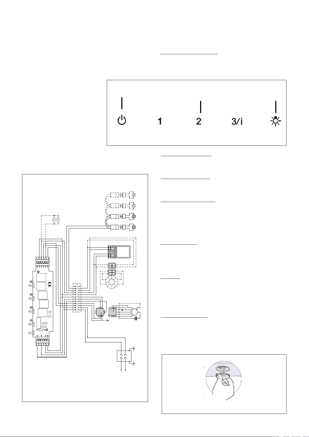
FIGURE 19
USE AND CARE INFORMATION
This rangehood system is designed to remove smoke, cooking
vapors and odors from the cooktop area.
Rangehood Control Panel
The control panel is located on the front edge of the rangehood
canopy. The position and function of each control button are
indicated in FIGURE 19.
For Best Results
Start the rangehood several minutes before cooking to develop
after cooking is complete to clear all smoke and odors from
the kitchen.
Cleaning
hot detergent solution or washed in the dishwasher. Stainless
steel cleaner should be used on stainless rangehoods. Abrasives
Replacing the Lamps
levering it from under the metal ring, supporting it with one hand.
Remove the halogen lamp from the lamp holder by pulling gently.
Replace the lamp with a new one of the same type, making
sure that you insert the two pins properly into the housings on
the lamp holder. Replace the snap-on lamp cover.
FIGURE 20
0 1 2 3 4 5 6 7 8 9
Creato da.
Rev :
Ver :
DOLCE CORRADO
Materiali: non deveno contenere Pb, Cr6+, Hg, PBB, pbde, ai sensi della direttiva 2002/95 CE
SCHEMA ELETTRICO M8-4V ESB FARETTI
Non rilevare quote dal grafico non app ortare modifiche senza l'autorizzazione d'ufficio progettazione
a termini di legge ci riserviamo la propr ieta' del presente disegno con divieto di ripr oduzione totale o parziale
Code :
Disegno N :
Data:
08.Set.2010
LINE IN
120Vac
60Hz ~
L
N
Y-G
WIRING BOX
BLU
RED
BLK
WHT
Y-G
1
2
3
4
5
6
BLK
V1
MC
F
V2
ESB
0
MOTOR
1
MOTOR
BRW
GRY
BLU
123
6 5 4
789
1 2 3
654
987
RED
M8 4V
120V ~
WHT
BRW
2
SPEED
BLU
BLK
1
1
BLK
BLK
WHT
2
2
WHT
ORG
BRW
3
3
BRW
GRY
4
4
GRY
RED
WHT
BLU
Y-G
BLU
5
5
BLU
3/I
SPEED
RED
6
6
RED
WHT
7
7
WHT
VLT(ORG)
8
8
VLT(ORG)
RED(ORG)
9
9
RED(ORG)
RED
10
10
RED
VLT
11
11
VLT
0-1
LIGHT
12
12
TOROIDAL
TRANSFORMER
WHT
4
3
BLK
RED
2
1
BLK
N
L
V4
L
V3
ORG
2
1
RED
ORG
4
3
VLT
WHT
1
2
3
4
5
6
ORG
WHT
BRW
GRY
ORG
RED(ORG)
VLT(ORG)
RED
VLT
PRI.
SEC.
ELECTRONIC
TRNSFORMER
VLT
RED
HALOGEN
LAMPS
VLT
INCANDESCENT
LAMP
RED
HALOGEN
LAMPS
HALOGEN
LAMPS
HALOGEN
LAMPS
L
M
V
Light On/Off Button ( L )
On/Off switch for the halogen lights. Press the light button to turn
the light ON. and again to turn off.
Blower Off Button ( M )
Off switch for the blower. The blower can be operated by pressing
any of the speed buttons
Blower Speed Button ( V )
Speed control for blower. Press the switch "1" for LOW speed,
speed 3 button for 5 seconds to activate the intensive speed. Which
operates the hood for 10 minutes on the high speed and then returns
the previous speed.
Loading ...
Loading ...
Loading ...