Loading ...
Loading ...
Loading ...
2. After the dryer has operated for three minutes, the exhaust air
or exhaust pipe should be warm.
Gas Dryers
IMPORTANT: This operation is to be conducted by
qualified personnel only.
1. To view the burner flame, remove the lower front panel of the
dryer.
2. Close the loading door and start the dryer in a heat setting (re-
fer to the operation instructions). The dryer will start, the ig-
niter will glow red and the main burner will ignite.
IMPORTANT: If all air is not purged out of gas line,
gas igniter may go off before gas is ignited. If this
happens, after approximately two minutes igniter
will again attempt gas ignition.
IMPORTANT: If igniter does not light, make sure gas
is turned on.
3. After the dryer has operated for approximately five minutes,
observe burner flame through lower front panel.
4. Adjust the air shutter to obtain a soft, uniform blue flame. (A
lazy, yellow-tipped flame indicates lack of air. A harsh, roar-
ing, very blue flame indicates too much air.) Adjust the air
shutter as follows:
a. Loosen the air shutter lockscrew.
b. Turn the air shutter to the left to get a luminous yellow-
tipped flame, then turn it back slowly to the right to obtain
a steady, soft blue flame.
c. After the air shutter is adjusted for proper flame, tighten
the air shutter lockscrew securely.
5. Reinstall the lower front panel.
WARNING
To reduce the risk of serious injury or death, low-
er front panel must be in place during normal op-
eration.
W158
6. After the dryer has operated for approximately three minutes,
exhaust air or exhaust pipe should be warm.
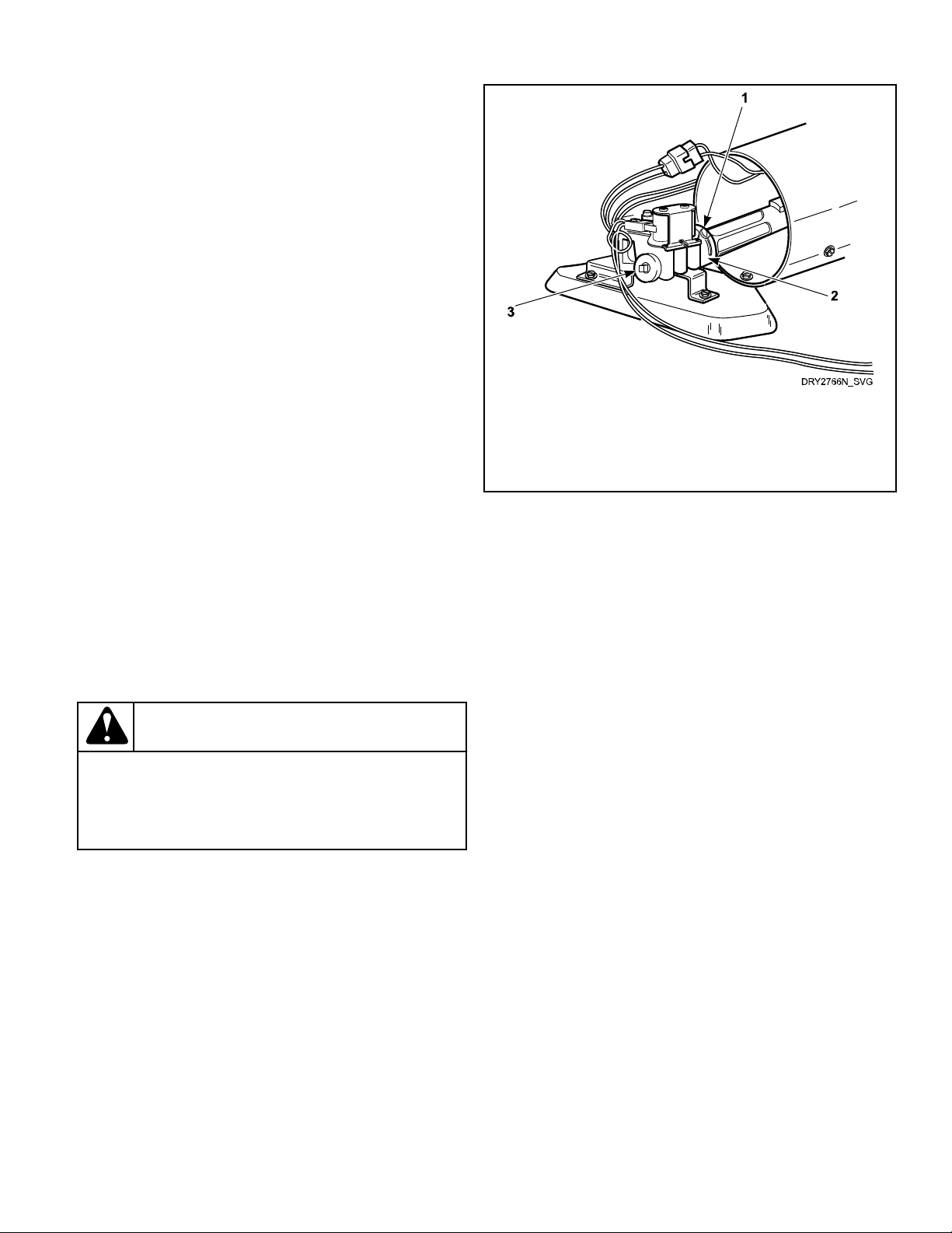
1. Air Shutter Lockscrew
2. Air Shutter
3. 1/8 in. [3.1 mm] Pipe Plug (For checking manifold pres-
sure)
Figure 34
Vending
Meter Case
The factory mounted coin meter case does not include the service
door lock, coin slide (if applicable), coin drawer, coin drawer
lock or keys. These parts must be ordered (at extra cost) accord-
ing to the purchaser’s requirements direct from the manufacturer
of your choice.
NOTE: You have the option of using a screw type lock
or a 1/4 turn lock on the meter case service door. If you
choose to use a screw lock, then the special bracket
(located inside the meter case) must be used. DO NOT
use the special bracket if a 1/4 turn lock is used.
Coin Drawer Security - For additional security, drill out the two
pilot holes on each side of the front of the meter case to 1/4 or
5/16 inch [6.4 or 7.9 mm] holes and install a bicycle lock through
these holes.
NOTE: An 8 in. [203 mm] coin drawer is required for
coin operated electronic control models.
Coin Slide and Non-Metered Models
Power-Up Mode
Shortly after power is applied to the dryer, the control will flash
once to indicate the machine is ready to be used. If a cycle was
running previously, the control will blink and then stay lit, indi-
cating there is still time remaining from the previous cycle. If the
control was not previously running a cycle, the control will be in
Ready Mode.
Ready Mode
Installation
©
Copyright, Alliance Laundry Systems LLC -
DO NOT COPY or TRANSMIT
33 Part No. D516119ENR3
Loading ...
Loading ...
Loading ...