Loading ...
Loading ...
Loading ...
DRY2468N_SVG
1
1. Earth/Ground Screw
Figure 19
4. Use a strain relief and insert end of power cord through power
supply hole.
DRY2469N_SVG
1. Strain Relief
Figure 20
5. Attach power cord earth/ground (green) wire to rear bulkhead
using earth/ground screw removed in Step 3.
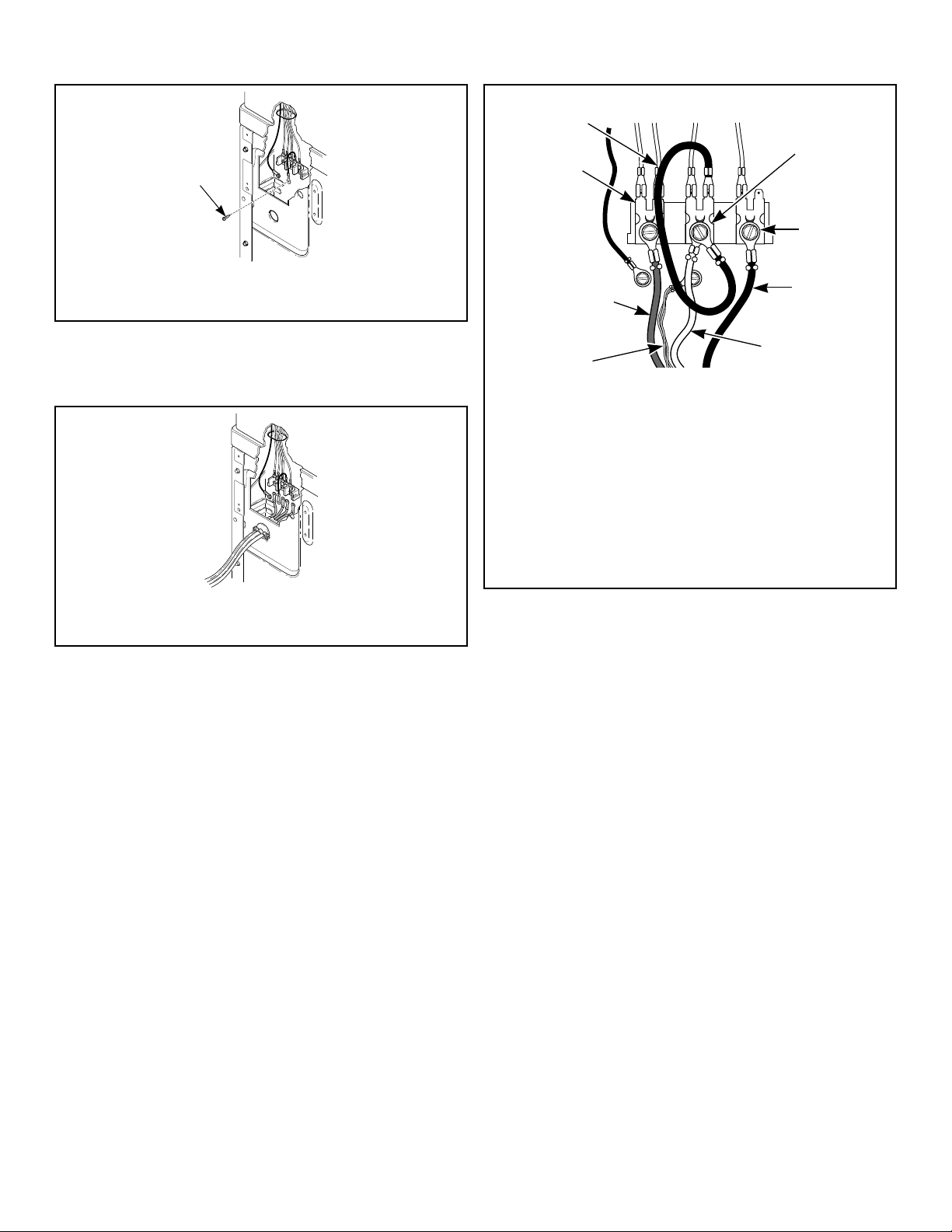
4-Wire Connection
DRY2482N_SVG
1
2
3
4
5
6
7
8
1. Neutral Terminal
2. “L2” Terminal
3. Black
4. White
5. Earth/Ground
6. Red
7. “L1” Terminal
8. Earth/Ground to Neutral Wire
Figure 21
6. Use the three screws from the accessories bag to attach the re-
maining power cord wires to the terminal block as follows:
a. Red wire to “L1” terminal.
b. Black wire to “L2” terminal.
c. White wire to Neutral terminal.
NOTE: When installing the white wire, loop the free
eyelet end of the earth/ground to neutral wire (re-
moved in Step 3) and attach along with the white
wire to the neutral (center) terminal on the terminal
block.
7. Using a screwdriver, tighten all screws firmly.
IMPORTANT: Failure to tighten these screws firmly
may result in wire failure at the terminal block.
8. Secure the strain relief to the power cord, or wires, where they
enter the dryer cabinet.
9. Check the continuity of the earth/ground connection before
plugging the cord into an outlet. Use an acceptable indicating
device connected to the center earth/ground pin of the plug
and the green screw on the back of the cabinet.
10. Reinstall access cover and screw.
Reverse Door, if Desired
NOTE: Doors with windows cannot be reversed.
Installation
©
Copyright, Alliance Laundry Systems LLC -
DO NOT COPY or TRANSMIT
29 Part No. D516119ENR3
Loading ...
Loading ...
Loading ...