V-ZUG Ltd
V-ZUG Ltd, Industriestrasse 66, CH-6301 Zug
[email protected], www.vzug.com
Planning aid
International collection
Kitchen appliances
J001059-R20
24.05.17
5
1
Overview of connections, ranges and dimensions
Electrical connections must be carried out by qualified experts in accordance with the guidelines and standards for low-
voltage installations and the specifications of the local electricity supply companies.
A plug-in appliance may only be connected to a socket outlet with earthing contact, installed according to specifications. An
all-pole mains isolating device with 3 mm contact opening should be provided in the house wiring system. Switches, plug
and socket devices, circuit breakers and fusible cut-outs which are accessible after installation and which have all-poles
switching are permissible as isolating devices. Effective earthing and separately installed neutral and earth conductors en-
sure safe and fault-free operation. After installation, live parts and cables with basic insulation must not be accessible.
Check old installations.
Electrical connections must be carried out by qualified experts.
Plan a separate inlet for the electrical connection for each appliance.
1.1
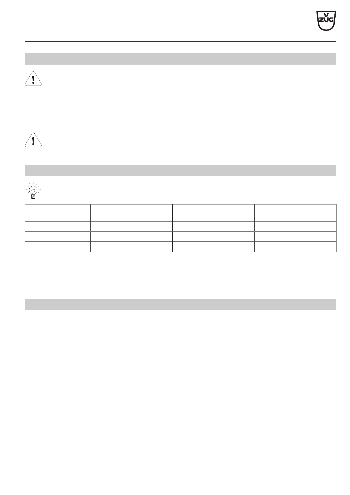
General operating conditions
Detailed information on the electrical connection data can be found at the beginning of each section.
Value Nominal value Minimum Maximum
Voltage 230 V 207 V 253 V
Voltage 400 V 360 V 440 V
Frequency 50 Hz sinusoidal 49 Hz sinusoidal 51 Hz sinusoidal
• Short duration frequency variation in the mains: ± 5 %
• Long duration frequency stability in the mains (for synchronous clocks): ± 10 ppm
• The appliances are designed for use up to a max. altitude of 2000 m above sea level.
1.2
Using residual current devices in house wiring system / fault current
High fault currents are inherently present in ovens and hobs. The values can be affected by various factors and vary widely. Fault
currents of up to approximately10mA per appliance are permissible in accordance with the norm. The values are measured in the
warm operating state.
If residual current devices (RCDs) are used in the house wiring system, we recommend that the above-mentioned appliances have
their own RCD protection, separate from the power supply for the rest of the system. 30mA or higher should be selected as the trip-
ping current for the residual current device.
V-ZUG Ltd
V-ZUG Ltd, Industriestrasse 66, CH-6301 Zug
[email protected], www.vzug.com
Planning aid
International collection
Kitchen appliances
J001059-R20
24.05.17
8
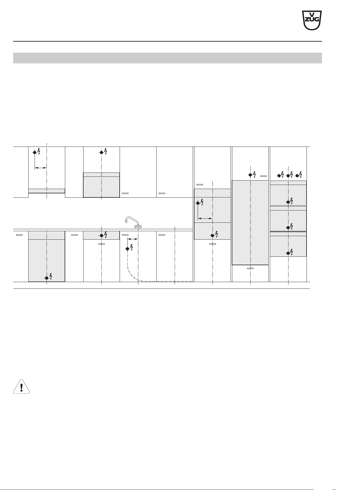
1.4
Positions of electrical connections
For EURO kitchens, allowance from the floor can vary. In this case, the electrical connection should be calculated using the dimen-
sion from the bottom edge of the appliance.
Oven above an oven
With this combination, an electrical connection should be provided for each appliance. Depending on the installation height and the
type of combination, the connections may be located at different heights.
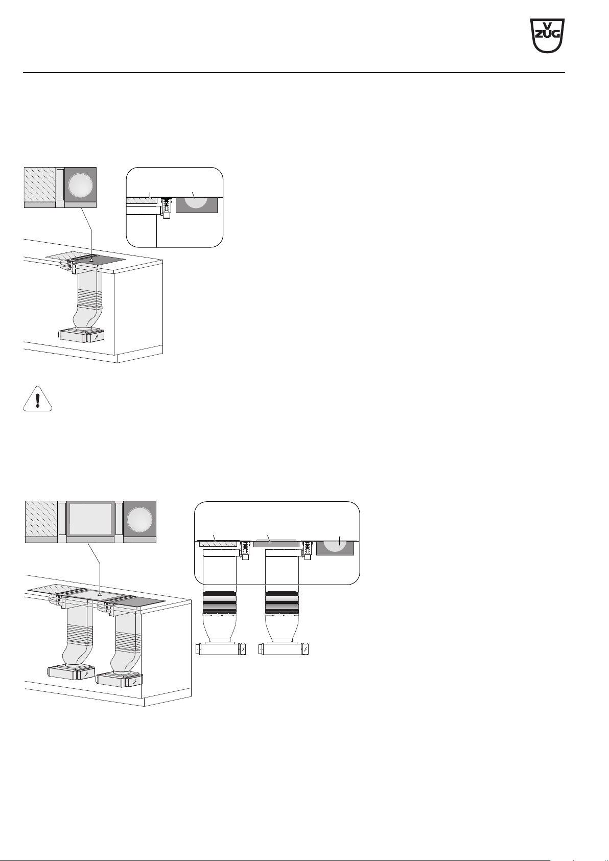
Wall hoods with telescopic casing
The electrical connection must pass between the exhaust air piping and the lagging sheets. The measurements given in the table en-
sure that this condition is met.
M3
7
M1
M2
6
1
3
4
5
2
8
1 Wide switch box / control box / autarchic hob
2 Refrigerator in base unit / dishwasher
3 Oven/coffee-center
4 Combinations (oven / steam cooker / microwave)
5 Refrigerator, winecooler in tall unit
6 Microwave in a wall unit
7 Range hood
8 Warming drawer
M1 Distance from centre to dishwasher/refrigerator connection in base unit
M2 Distance from centre to coffee-center connection
M3 Distance from centre to range hood connection
Provide additional clearance for electrical connections if the installation niche has only the minimum depth.
V-ZUG Ltd
V-ZUG Ltd, Industriestrasse 66, CH-6301 Zug
[email protected], www.vzug.com
Planning aid
International collection
Kitchen appliances
J001059-R20
24.05.17
62
11
Range hoods
Technical information on the range hoods can be found in the document J32836 «TechInfo for range hoods».
11.1
General notes
If other firing systems are being used at the same time (e.g. wood, gas, oil or coal fired heating appliances), safe operation
is only possible providing a room negative pressure of 4Pa (0.04mbar) is not exceeded at the location of the appliance.
Risk of toxic fumes! An adequate flow of fresh air must be guaranteed e.g. via non-closable openings in doors or windows
and in combination with an air-intake/exhaust-air wall box or by other technical means.
Efficient repairs can only be guaranteed if it is possible to uninstall the whole appliance at any time without causing any
damage.
Minimum distance to the hob
If a V-ZUG appliance is being combined with a third-party brand (hob or range hood) and the stipulated minimum distance
between the combined appliances is different, then the greater of the two must be observed. The minimum distance is
measured between the bottom edge of the range hood and the bottom of the pot or pan.
If the appliance is installed over gas hobs, each cooking zone must be fitted with an ignition fuse.
Extraction mode
The extracted air must not be fed into a chimney which is used for exhausting fumes from appliances burning gas or other
fuels.
Observe the local fire regulations.
Installation notes
• In addition to the correct dimensioning of the exhaust duct, it is also necessary to ensure a sufficient inflow of fresh air.
to replace the air that is being extracted.
• Avoid routing the exhaust duct to the side through the chimney casing.
• Planning features for non-destructive de-installation and maintenance of the appliance:
– Do not route telescopic casing in suspended ceilings.
– Avoid silicone joints between the telescopic casing and the appliance.
– All plastering, plasterboarding, wall papering or painting work is to be carried out prior to installing the appliance.
11.2
Special hoods
Special hood type DSTS9 (64004) may not be used in combination with gas hobs.
Special hood type DSMS (64005) may only be operated in combination with a gas hob of V-ZUG gas hob type:
GAS321GKBZ, GAS321EKBZ, GAS421GSAZ, GAS421GSBZ, GAS641GKAZ, GAS641EKAZ, GAS641GSAZ,
GAS641GSBZ, observing the permitted combination installation variants. The content of the operating and installation in-
structions for the listed gas hob must be observed! If operating a permitted gas appliance, the hob hood must be fitted with
the dedicated gas deflector 1031218 (accessory)! Operating a gas appliance without the gas deflector is not permitted!
V-ZUG Ltd
V-ZUG Ltd, Industriestrasse 66, CH-6301 Zug
[email protected], www.vzug.com
Planning aid
International collection
Kitchen appliances
J001059-R20
24.05.17
63
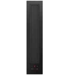
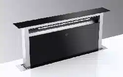
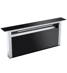
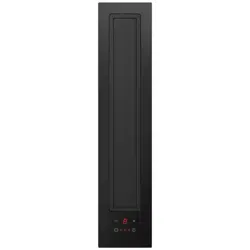
DSMS (64005)
Operating mode Extraction/recirculation Mains connection 220–240V~ 50/60Hz
Noise level 62–70dB(A) Fuse 10A
Illumination - Fan speeds 4
Motor 1×145W Weight ~21.5 kg
468
523
386
370
185
185
50
110
233
77
300
217
145
16
118
266
ø190
52
102
86
86
M
E
T
L
U
H
Q
370
370
217
10
185
30
50
60
250
266
266
ø190
220
86
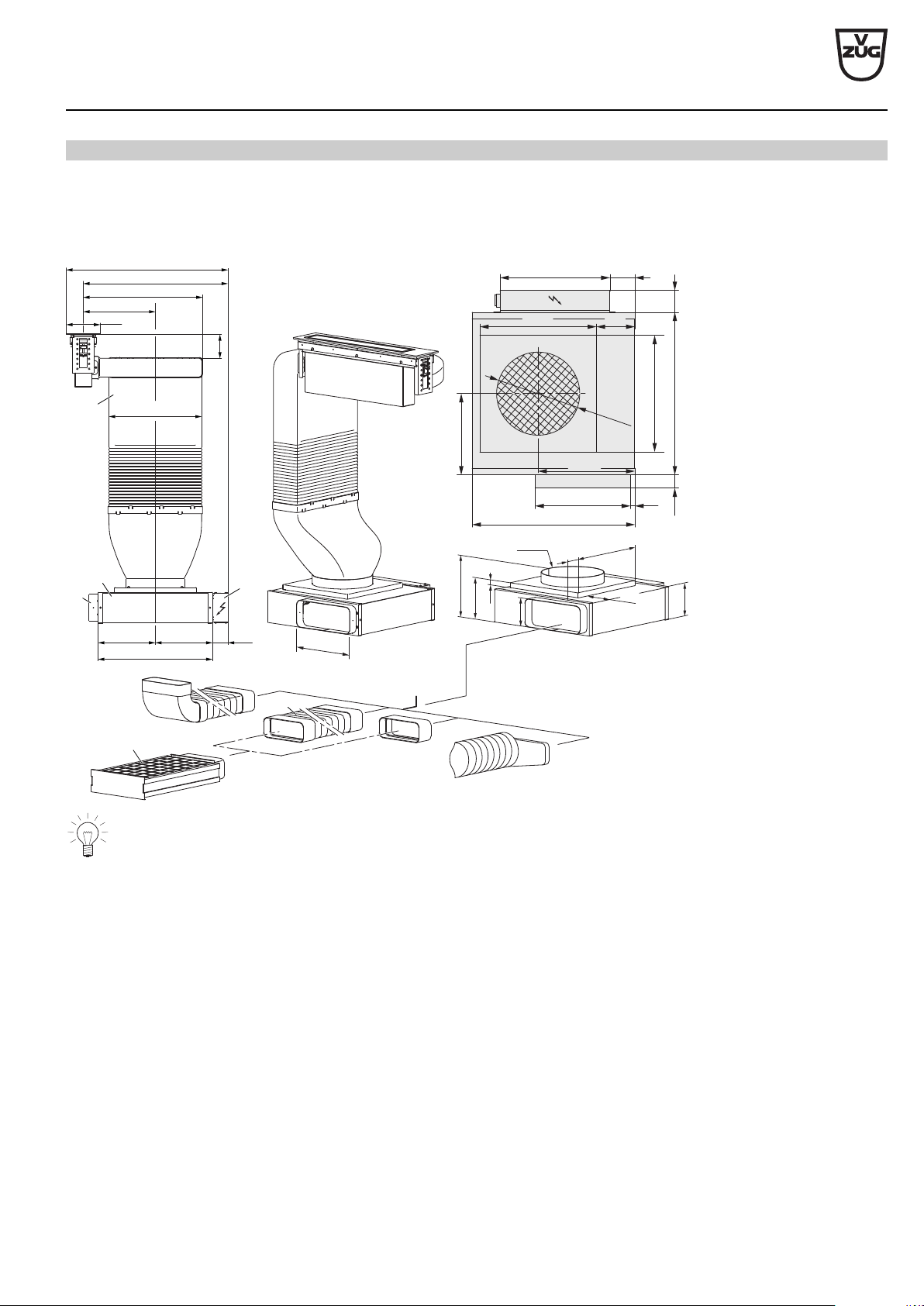
Suitable flat channel systems Q are available for order as accessories.
• The connection between the hob hood and the exhaust air duct T can be to the left or right.
• The ventilation outlet L can be fed through one of the four sides, however this can change the installation type.
• Depending on space requirements, the exhaust ducting T can be adjusted through shortening.
• The control unit E can be repositioned (≤250 mm) if required.
• Plan a removable base plate or service flap for fan motor M and recirculation box U (for recirculation mode).
• Access to the fan motor M and the recirculation box U is facilitated through extendible flat channel systems Q.
Recommendation: Flat flexible elbow H, article no. 1012786 with flexible length (240–600 mm).
• For the recirculation mode, ensure sufficient ventilation so that moisture can escape. Plan in suitable material/wood.
V-ZUG Ltd
V-ZUG Ltd, Industriestrasse 66, CH-6301 Zug
[email protected], www.vzug.com
Planning aid
International collection
Kitchen appliances
J001059-R20
24.05.17
64
p
stat
[mm WS/CE]
p
stat
[P
a
]
0
100
200
300
400
500
600
0
400300200100 500 600
700
800
0
10
20
30
40
50
60
70
80
2
1
3
Flow volume [m
3
/h]
4 intensive
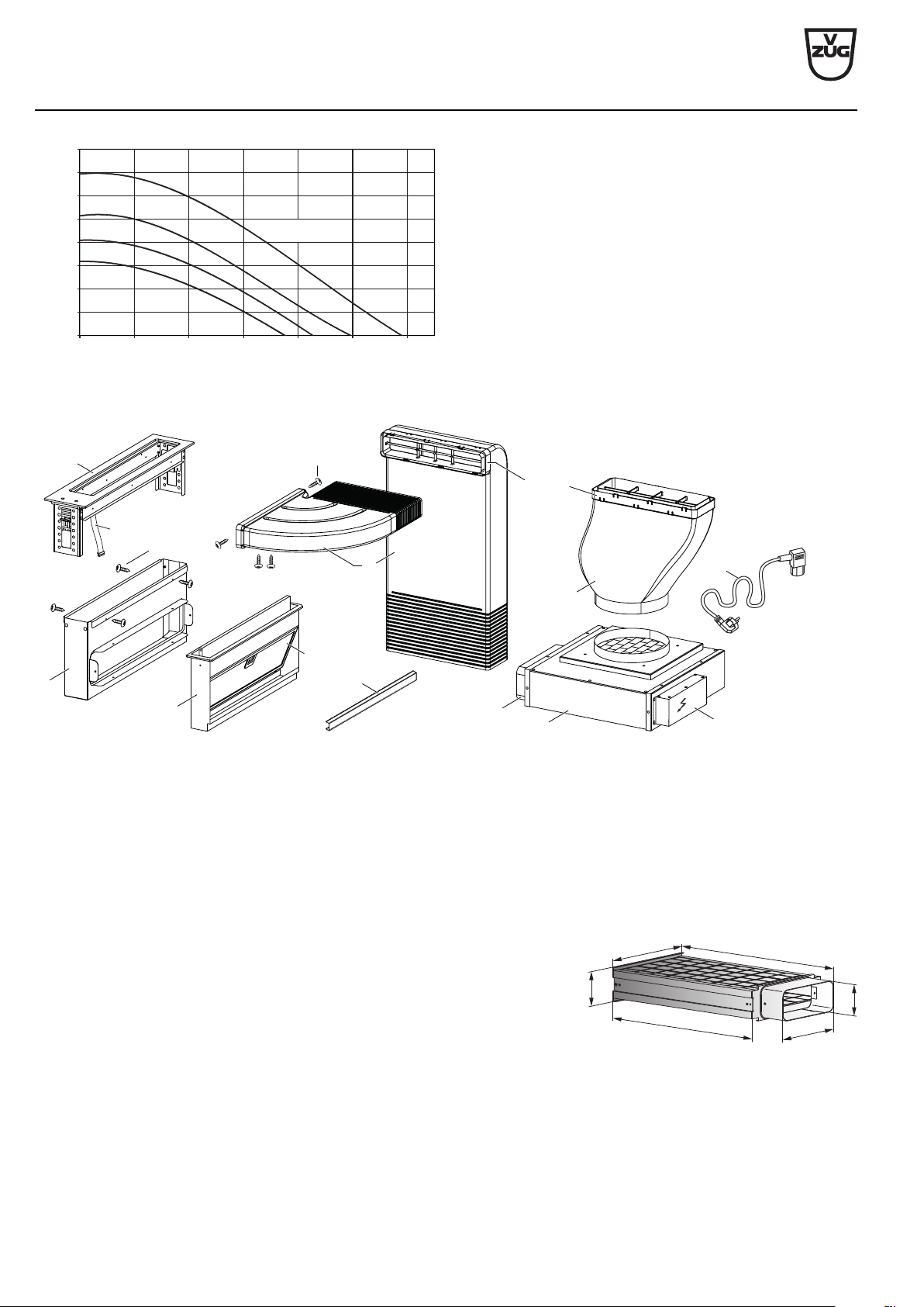
Scope of delivery
S1 (12×)
M
U (2×)
E
S2 (4×)
A
T
F
G
N
L
T
V (2×)
R
K
A Drip tray frame N Mains cable length 1.8m
E Control unit Q Flat channel system
F Metal grease filter R Frame
G Appliance housing T Exhaust air duct
K Control cable U Spacer profile
L Ventilation outlet V Connecting elements
M Fan motor
Accessories:
Recirculation box 1012161
The flat channel system Q (accessories) can be used for the installation. Flat chan-
nel systems made of plastic (see page 131)
222
600
515
305
100
90
V-ZUG Ltd
V-ZUG Ltd, Industriestrasse 66, CH-6301 Zug
[email protected], www.vzug.com
Planning aid
International collection
Kitchen appliances
J001059-R20
24.05.17
65
Gas deflector 1031218, required accessory when using a permitted V-ZUG gas
hob. Operating a gas appliance without the gas deflector is not permitted!
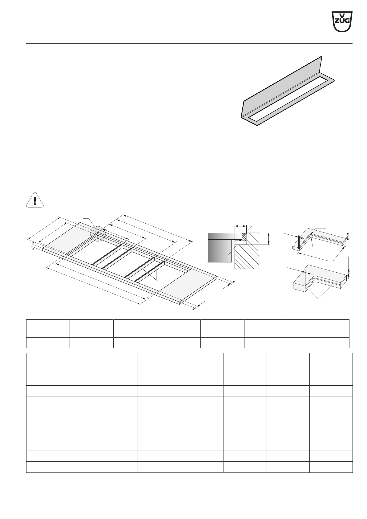
Combination installation
Flush installation
Flush-mounted installation with additional intermediate supports K requires the accessory intermediate support set H63789 (con-
tains two intermediate supports). Flush-mounted combination installation is described in document 1014381.
A WOK glass ceramic hob cannot be surface mounted!
Reason: Glass thickness is 6mm.
Silicone joints
Spacer plates
Detail Z
Steel angle mounted
with adhesive or screws
8.5
+1
0
8.5
0
-1
8.5
+1
0
8
.5
0
-1
8.5
0
-0.5
8.5
+1
0
G
3
G2
G1
G4
C
E
I
J
F
A
D
Z
K
C
4
90
R0–5
Ra
A F D I J Ra K
≥30mm 507±1mm 490±1mm ≥41.5mm ≥41.5mm 5mm Intermediate support
Combinations Cut-out
width E
Cut-out
width C
Intermediate
support
position G1
Intermediate
support
position G2
Intermediate
support
position G3
Intermediate
support
position G4
30+11+30cm 684mm 667mm 285.5mm 398.5mm - -
30+11+40cm 787mm 770mm 285.5mm 398.5mm - -
40+11+40cm 890mm 873mm 388.5mm 501.5mm - -
11+80+11cm 993mm 976mm 114.5mm 878.5mm - -
40+11+40+11+40cm 1390mm 1373mm 388.5mm 501.5mm 888.5mm 1001.5mm
40+11+60+11+40cm 1577mm 1560mm 388.5mm 501.5mm 1075.5mm 1188.5mm
40+11+70+11+40cm 1697mm 1680mm 388.5mm 501.5mm 1195.5mm 1308.5mm
40+11+80+11+40cm 1767mm 1750mm 388.5mm 501.5mm 1265.5mm 1378.5mm
V-ZUG Ltd
V-ZUG Ltd, Industriestrasse 66, CH-6301 Zug
[email protected], www.vzug.com
Planning aid
International collection
Kitchen appliances
J001059-R20
24.05.17
66
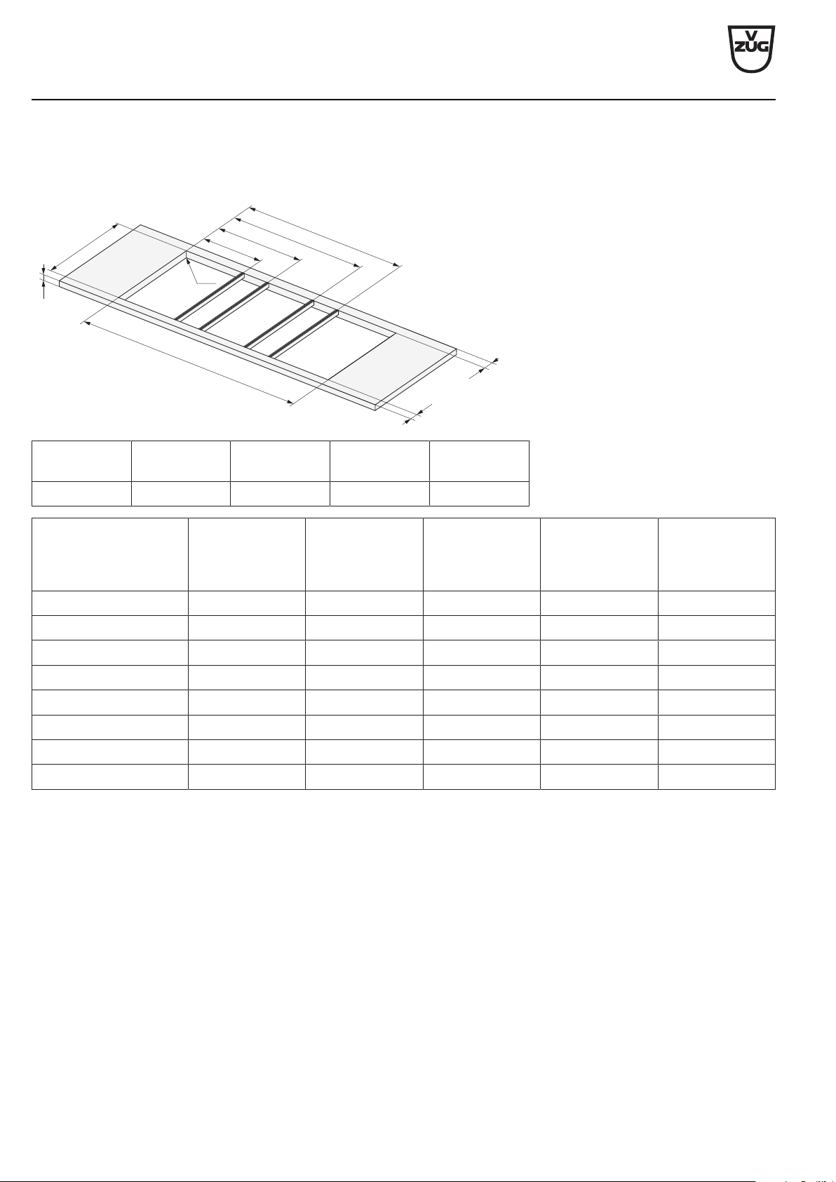
Surface-mounted installation
Surface-mounted installation requires the accessory side strip set 1028587 and either the intermediate support K 1019199 (black)
or 1014361 (stainless steel). Articles are available for order as accessories. Surface-mounted combination installation is described in
document 1013773.
G3
G2
I
J
C
D
A
Ra
G1
G4
A D I J Ra
≥30mm 490±1mm ≥50mm ≥50mm 0–5mm
Combinations Cut-out
width C
Intermediate
support
position G1
Intermediate
support
position G2
Intermediate
support
position G3
Intermediate
support
position G4
30+11+30cm 667mm 277mm 390mm - -
30+11+40cm 770mm 277mm 390mm - -
40+11+40cm 873mm 380mm 493mm - -
11+80+11cm 976mm 106mm 870mm - -
40+11+40+11+40cm 1373mm 380mm 493mm 880mm 993mm
40+11+60+11+40cm 1560mm 380mm 493mm 1067mm 1180mm
40+11+70+11+40cm 1680mm 380mm 493mm 1187mm 1300mm
40+11+80+11+40cm 1750mm 380mm 493mm 1257mm 1370mm
V-ZUG Ltd
V-ZUG Ltd, Industriestrasse 66, CH-6301 Zug
[email protected], www.vzug.com
Planning aid
International collection
Kitchen appliances
J001059-R20
24.05.17
67
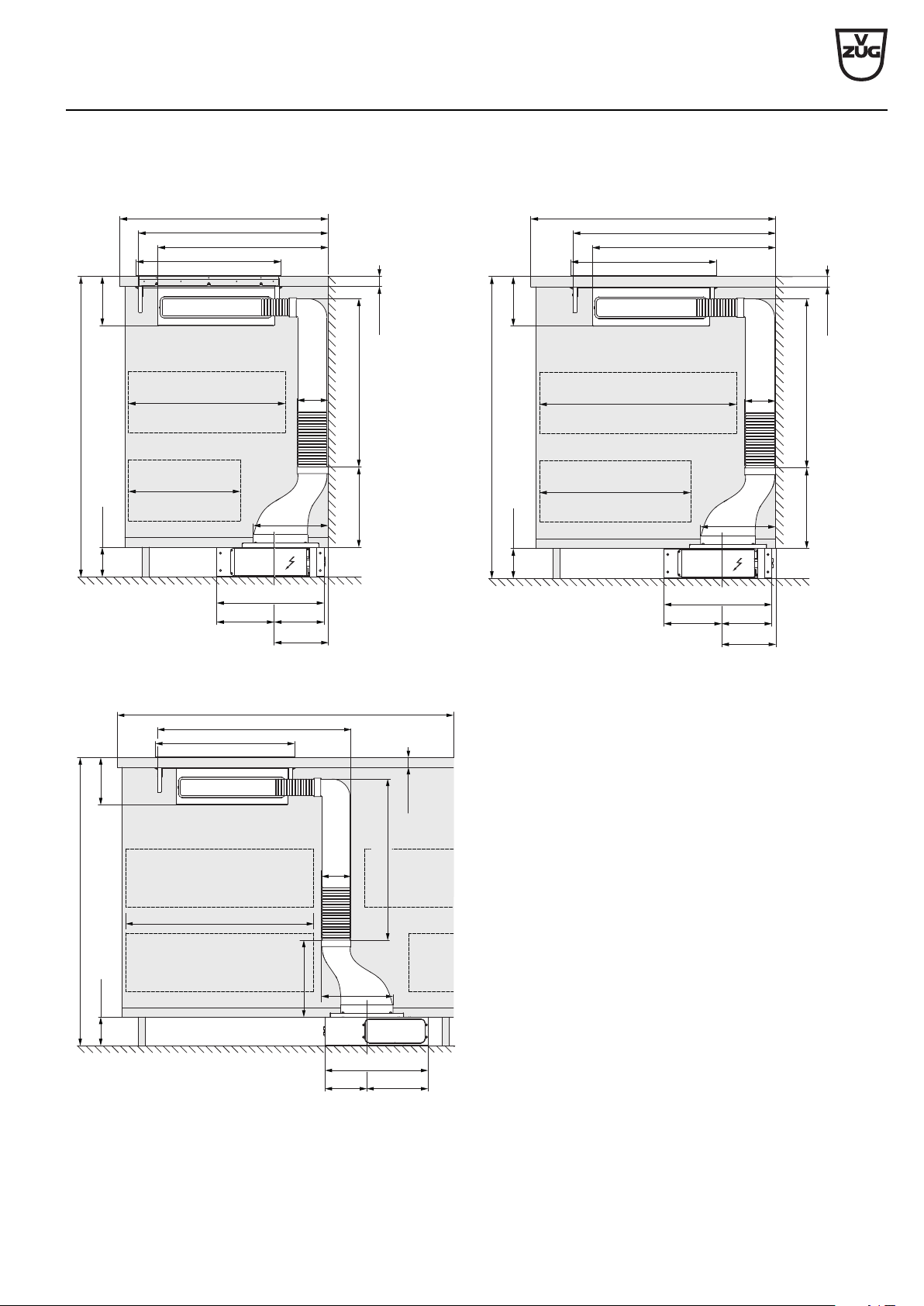
Installation overview for base
Wall installation, depth ≥600 mm Wall/island installation, depth ≥700 mm
900–1050
≥105
220 150
163
174*
390–590
268
30–70
258
105
370
548–698
≥600
479–629
≤300
≤400
501
900–1050
≥105
220 150
163
174*
390–590
268
30–70
258
105
370
548–698
≥700
479–629
≤400
≤500
501
Island installation, depth ≥800 mm
900–1050
≥105
220
150
174*
390–590
2
68
30–70
258
105
370
≥800
≤500
501
548–698
* Flush installation. Surface-mounted installation: 170 mm.
V-ZUG Ltd
V-ZUG Ltd, Industriestrasse 66, CH-6301 Zug
[email protected], www.vzug.com
Planning aid
International collection
Kitchen appliances
J001059-R20
24.05.17
68
Appliance selection and combination possibilities
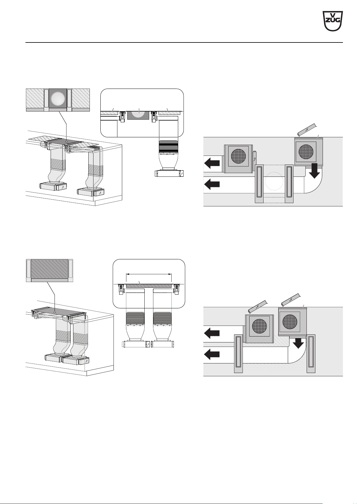
1. Planning example: Two hobs
Air duct in base to left/right.
The WOK glass ceramic hob / gas hob W is always positioned on the opposite side of the exhaust air duct. Standard hob S.
!
W
S
A WOK glass ceramic hob and gas hob may not be combined! In general, the use of a gas wok, in any combination, is not
permitted.
2. Example: Three hobs
Air duct in base on both sides to left/right.
The Teppan Yaki hob P (600 mm) is positioned in the middle. The WOK glass ceramic hob / gas hob W is always positioned on the
opposite side of the exhaust air duct. Standard hob S.
!
P
S
W
V-ZUG Ltd
V-ZUG Ltd, Industriestrasse 66, CH-6301 Zug
[email protected], www.vzug.com
Planning aid
International collection
Kitchen appliances
J001059-R20
24.05.17
69
3. Example: Three hobs
Air duct in base on both sides to outside.
The WOK glass ceramic hob / gas hob W (400 mm) is positioned in the middle. Standard hob S. Possible position of 2 fan motors M.
!
W
S
S
M
4. Example: Large hob positioned in the middle
Air duct in base on both sides to inside for space economy.
Allows standard hob S with ≤800 mm installation width to be positioned in the middle. The WOK glass ceramic hob / gas hob W can
not be positioned in the middle. Possible position of 2 fan motors M.
≤800
M
S
V-ZUG Ltd
V-ZUG Ltd, Industriestrasse 66, CH-6301 Zug
[email protected], www.vzug.com
Planning aid
International collection
Kitchen appliances
J001059-R20
24.05.17
70
For use with a gas appliance
The hob hood may only be used with the dedicated gas deflector 1031218 (accessory) with one of the gas appliances listed
below. Operating the hob hood without the gas deflector is not permitted!
Permitted gas appliances for use with the hob hood:
V-ZUG gas hob type: GAS321GKBZ, GAS321EKBZ, GAS421GSAZ, GAS421GSBZ, GAS641GKAZ, GAS641EKAZ,
GAS641GSAZ, GAS641GSBZ, observing the permitted combination installation variants.
Combining the hob hood with two gas hobs is not permitted!
Using another gas appliance type/model or manufacturer is not permitted and can cause lasting damage to the hob hood.
Failure to observe the above instruction can cause lasting bodily harm and lasting damage to property and the appliance. In
such a case, any and all liability, guarantee and goodwill claims will be rejected, now and in the future!
Risk of burns!
The appliance and surrounding components get hot during operation! Allow the fan flap, gas deflector and other compon-
ents to cool down before touching them.
Fire hazard!
Grease deposits can build up in the grease filter and catch fire. Clean the grease filter regularly. Only operate the appliance
with the gas deflector.
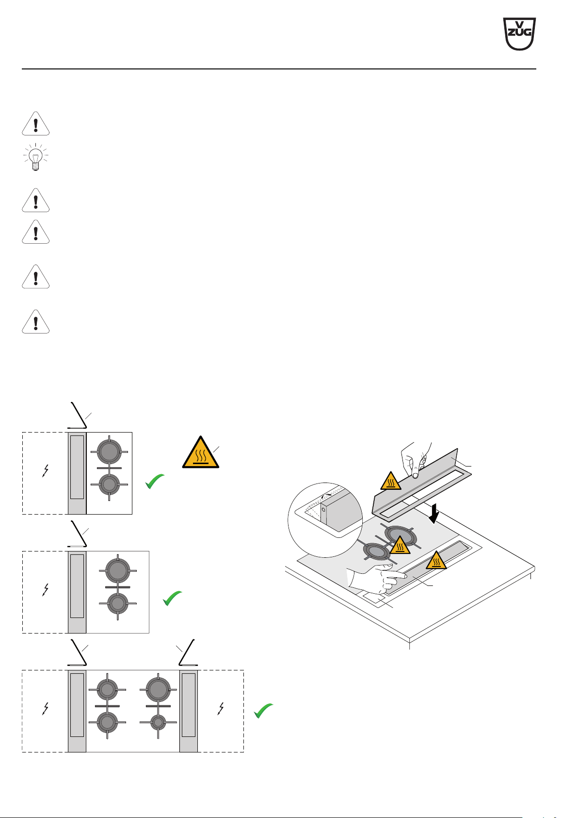
Permitted installation variants (V-ZUG gas hob only)
As a variant may also be installed on either side of the appliance.
The gas deflector 1031218 (required accessory) reduces the
deflection/disturbance of the gas flame at the burner and pre-
vents it being extinguished by a draft.
► Open fan flap 1.
A Caution: Hot surface!
B Gas deflector correctly mounted.
B
B
B
B
A
► Set the gas deflector 2 in the correct position relative to the
gas appliance.
► Switch on hob hood 3.
1
3
2
V-ZUG Ltd
V-ZUG Ltd, Industriestrasse 66, CH-6301 Zug
[email protected], www.vzug.com
Planning aid
International collection
Kitchen appliances
J001059-R20
24.05.17
71
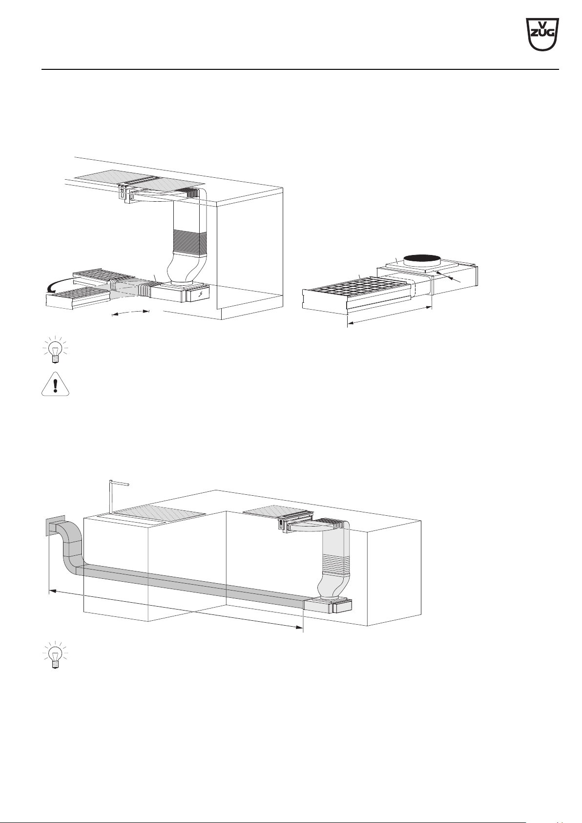
Installation variant for recirculation hob hood with recirculation box
Example: Recirculation mode with recirculation box
Flat flexible elbow, H, article no. 1012786 with flexible length (240–600 mm) easy installation/access to fan motor M and recirculation
box U.
2
4
0
–
6
0
0
H
35
≥845
U
M
Plan in enough space for maintenance work and ensure access to the fan motor and the recirculation box (for re-
placing the activated charcoal filters)!
Dedicated accessories that need to be fitted to operate the appliance in the recirculation mode: article no. 1012161 recircu-
lation box with activated charcoal filters!
Installation variant for extraction hob hood
Example: Extraction mode with flat channel (round channel also possible).
Plan in length of flat channel system to air outlet of max. 7000 mm. If the exhaust duct is to be routed outdoors, we recommend in-
stalling a telescopic wall box (accessory available for order).
≤7000
Ensure enough space for maintenance work and access to the fan motor and flat channel system!