Eagle
®
NX Torso Rotation
Owner's Manual
Part Number
20190-999-4 AB


Table of Contents
Safety
Safety Guidelines and Practices.................................................................................................4
Anchoring Equipment..................................................................................................................4
Facility Safety Precautions..........................................................................................................4
User Safety Precautions...............................................................................................................5
Warnings and Cautions................................................................................................................6
Label Placement...........................................................................................................................7
Assembly
Machine Specifications................................................................................................................8
Choosing and Preparing a Site...................................................................................................8
Environment..................................................................................................................................8
Verify Parts List Below..................................................................................................................9
Tools Required..............................................................................................................................9
Assembly Procedure..................................................................................................................10
Exercise
Intended Use................................................................................................................................18
Instructions..................................................................................................................................18
Maintenance
Warnings.......................................................................................................................................19
Daily Procedures.........................................................................................................................19
Weekly Procedures.....................................................................................................................20
Yearly Procedures.......................................................................................................................21
Cable Adjustment.......................................................................................................................21
Customer Service
Product Registration..................................................................................................................23
Contacting Service......................................................................................................................23
Ordering Parts.............................................................................................................................23
Return Material Authorization (RMA)......................................................................................23
Damaged Parts............................................................................................................................24
Cybex
®
and the Cybex logo are registered trademarks of Cybex International, Inc. Eagle
®
and its mark are registered trademarks of Cybex International, Inc.
DISCLAIMER: Cybex International, Inc. makes no representations or warranties regarding the contents of this manual. We reserve the right to revise this document
at any time or to make changes to the product described within it without notice or obligation to notify any person of such revisions or changes.
©
Copyright 2017, Cybex International, Inc.
Columbia Center III - 9525 West Bryn Mawr Ave, Rosemont, IL 60018 • 800-351-3737 • 847-288-3700 • FAX 800-216-8893
www.cybexintl.com • 20190-999-4 AB • June 2017
Page 3 of 25

Safety
Safety Guidelines and Practices
Read the Owner’s Manual carefully before assembling, servicing, or using the equipment. Owner must
comply with all safety guidelines in this manual. It is also the owner’s responsibility to instruct users on the
safe and proper operation of the equipment and to properly display any and all warning labels and
instructional placards. All users should read these labels and placards before using equipment.
Serious injury or death could occur if the following safety precautions and instructions
are not followed.
Anchoring Equipment
Owner should not allow equipment to be used until it is properly anchored as described below.
Anchoring equipment:
• To maximize stability and eliminate rocking, tipping, or falling over, equipment
must be anchored to a solid, level surface, utilizing all anchoring holes provided.
• Fasteners must have a minimum of 500 lbs. tensile capacity. Cybex recommends
.3/8” grade 2 bolts or better. A minimum pull force of 220 lbs/100 kgs is required
for each anchor position.
• If leg frames do not contact surface, DO NOT pull down with anchors. Shim any
leg or frame not in contact with surface using flat washers.
• Due to the wide variation of flooring on which machines may be anchored or
installed, consult with a qualified and licensed contractor to ensure proper
anchoring and installation.
Facility Safety Precautions
Do not allow anyone, including trainers, to use equipment in a manner other than that shown on the warning
labels and instructional placards located on every machine.
Do not install equipment on an uneven surface. The solid, level surface should not deviate more than 1/8” over a
10’ distance or as defined and required by local building and architectural codes.
It is the responsibility of the facility owner/owner of the equipment to ensure that there is appropriate clearance
around each machine to allow for safe use and passage.
In compliance with the ADA (American Disabilities Act) there must be clear floor space of at least 30 by 48 inches
and be served by an accessible route for at least one of each type of exercise equipment. If the clear space is
enclosed on three sides (e.g., by walls or the equipment itself), the clear space must be 36 by 48 inches.
All other machines must have a clear floor space of 23” for all access point on the machine, unless shown in the
Owner’s Manual.
The dimensions stated in the assembly instructions of this manual include the maximum foot print (in use)
dimensions.
All equipment should be used in a supervised, access-controlled area.
Do not allow equipment to be used by children 12 and under. Supervise disabled and children 13 and older.
Page 4 of 25

The owner should ensure that regular inspection and maintenance checks as detailed in this manual are performed.
Keep a log of all maintenance and repair activities.
Each day before use, the owner should inspect the equipment. If there are any loose or worn components such
as belts, cables, grips, pulleys, or any missing, damaged labels, or placards, the owner should fix any deficiencies
before they allow the equipment to be used.
Use only Cybex components to maintain and repair the equipment.
Display the Facility Safety Sign so it is visible and prominent.
User Safety Precautions
Owners must instruct users to DO the following:
• Follow all warning labels and instructional placards when using equipment.
• Insert weight pin completely before using selectorized equipment.
• Consult a physician prior to commencing an exercise program. If at any time during exercise you feel faint, dizzy
or experience pain, stop and consult your physician.
• Use a spotter for Free Weight equipment.
Owners must instruct users to NOT DO the following:
• DO NOT pin weights on selectorized equipment in an elevated position or use the machine if found in this
position
• DO NOT increase weight resistance on equipment by any means other than those provided by Cybex.
• DO NOT wear loose or dangling clothing or jewelry while using equipment. Stay clear of moving parts.
• DO NOT lean or pull on machine
• DO NOT use machine for support during stretching.
• DO NOT attach resistance straps, ropes or other means to equipment, except those provided by the manufacturer
for intended use on the equipment.
• DO NOT exceed the maximum specified user weight.
• DO NOT use if equipment appears damaged or inoperable upon inspection
• DO NOT use if guards are missing or damaged.
• DO NOT remove any labeling from equipment.
Page 5 of 25
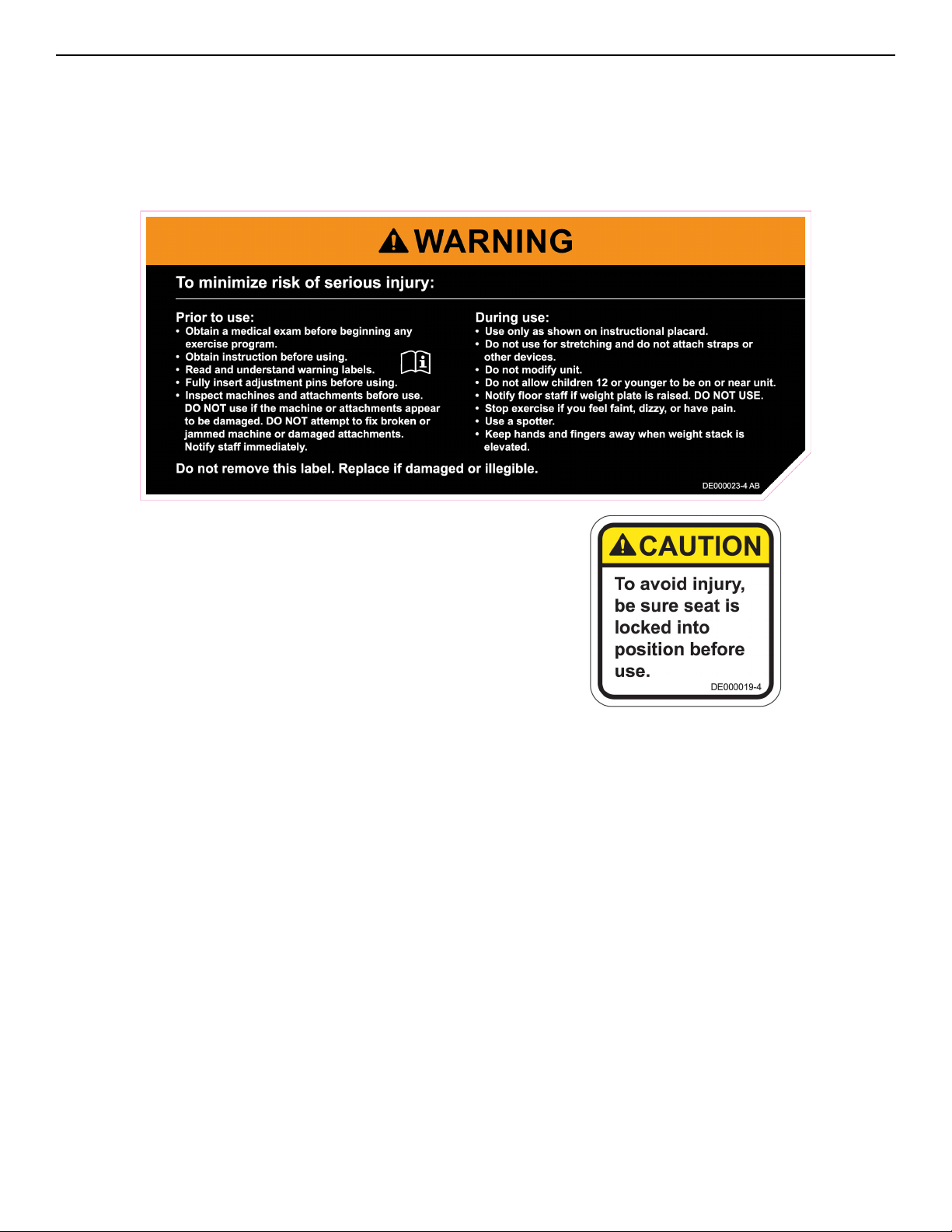
Warnings and Cautions
Warning labels indicate a potentially hazardous situation that could result in serious injury or death if the precautions
are not observed.
Caution labels indicate a potentially hazardous situation that could result in serious injury or damage to machine
if the precautions are not observed.
Contact Cybex Customer Service to replace any worn or damaged labels.
Page 6 of 25
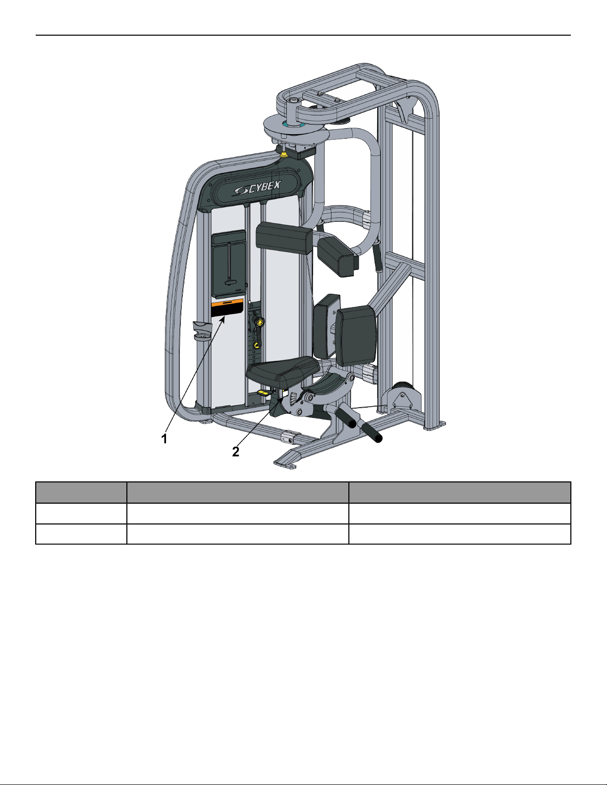
Label Placement
The following diagram shows where each label is located.
QtyDescription
1DE000023-X1
1DE000019-X2
Page 7 of 25
Assembly
Machine Specifications
Total Weight and Size 20190 Torso Rotation
Machine Dimensions in UseMachine Dimensions at RestWeight
46” L x 53” W x 79” H46” L x 47” W x 79” H574 Lbs
117 cm L x 135 cm W x 201 cm H117 cm L x 119 cm W x 201 cm H260 Kg
Maximum Training WeightMaximum User Weight
205 lbs/93 kg300 lbs/135 kg
Choosing and Preparing a Site
Before assembling the unit, verify the chosen site meets the following criteria:
• Area is well lit and well ventilated.
• Surface is structurally sound and properly leveled.
• Free area for access to unit and emergency dismount. Minimum clearance is 23.6 inches (0.6 meters).
• Adjacent units may share the free area.
It is the responsibility of the facility owner/owner of the equipment to ensure that there is appropriate clearance
around each machine to allow for safe use and passage.
In compliance with the ADA (American Disabilities Act) there must be clear floor space of at least 30 by 48 inches
and be served by an accessible route for at least one of each type of exercise equipment. If the clear space is
enclosed on three sides (e.g., by walls or the equipment itself), the clear space must be 36 by 48 inches.
All other machines must have a clear floor space of 23” for all access point on the machine, unless shown in the
Owner’s Manual.
Environment
Humidity and Static Electricity
The unit is designed to function normally in an environment with a relative humidity range of 30% to 75%. The
unit can be shipped and stored in a relative humidity range of 10% to 90%.
Climatic dry air may cause static electricity. During workout, user may experience a shock due to build up of static
electricity on the body and the discharge path of the unit. If static electricity is experienced, increase humidity to
a comfortable level through the use of a humidifier.
Page 8 of 25
Do not install, use or store the unit in an area of high humidity, such as in the vicinity of a steam room, sauna,
indoor pool or outdoors. Exposure to extensive water vapor, chlorine and/or bromine could adversely affect other
parts of the unit.
Temperature
The unit is designed to function normally in an environment with an ambient temperature range of 50° F (10° C)
to 104° F (40° C). The unit can be shipped and stored in an environment with an ambient temperature range of 32°
F (0° C) to 140° F (60° C).
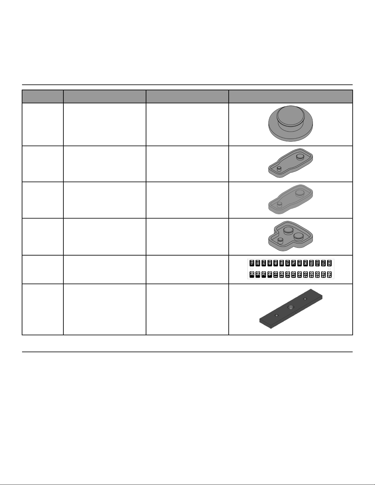
Verify Parts List Below
DiagramDescriptionPart NumberQty
Foot Pad20000-3392
Foot Pad20000-3762
Foot Pad20000-3772
Foot Pad20000-3782
Decal, Weight Plate (30-290)12000-5601
Weight Stack Plate4000C1019
Tools Required
• 7/32” Allen wrench
• 5/16" Allen wrench (2)
• 3/4” Socket wrench
• Hammer
• 3/16” Pin punch
• Phillips screwdriver
•
Loctite
®
#242
• Medium weight automotive engine oil
• Clean cloth
Page 9 of 25

Assembly Procedure
Two people will be required for this procedure.
Read and understand all instructions thoroughly before assembling this unit. Check all items carefully. If
there is damage, see the Customer Service section of this manual for proper procedure to return, replace,
or reorder parts.
If machine CAN fit through doorway
Two people will be required for this procedure
1. Move to desired location.
2. Remove shipping cones using a 3/4” socket or wrench.
3.
Remove bolt from shipping cone with hammer. Recycle cone.
4. Attach foot pads to each foot of frame.
5. If weight stack needs to be installed, follow procedure for installing weight plates and weight plate decal.
Securely anchor machine to floor
Owner should not allow equipment to be used until it is properly anchored as described below.
Anchoring equipment:
• To maximize stability and eliminate rocking, tipping, or falling over, equipment
must be anchored to a solid, level surface, utilizing all anchoring holes provided.
• Fasteners must have a minimum of 500 lbs. tensile capacity. Cybex recommends
.3/8” grade 2 bolts or better. A minimum pull force of 220 lbs/100 kgs is required
for each anchor position.
• If leg frames do not contact surface, DO NOT pull down with anchors. Shim any
leg or frame not in contact with surface using flat washers.
• Due to the wide variation of flooring on which machines may be anchored or
installed, consult with a qualified and licensed contractor to ensure proper
anchoring and installation.
Verify proper operation
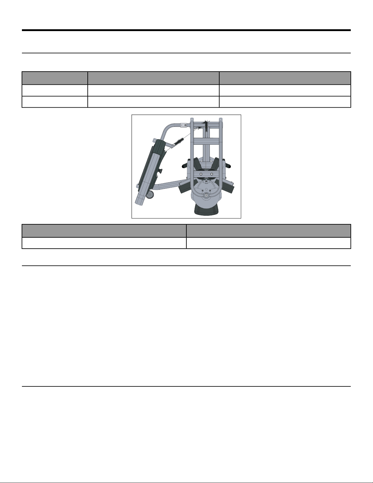
If machine CANNOT fit through doorway
Two people will be required for this procedure
1. Remove shipping cones using a 3/4” socket or wrench.
2.
Remove bolt from shipping cone with hammer. Recycle cone.
Page 10 of 25
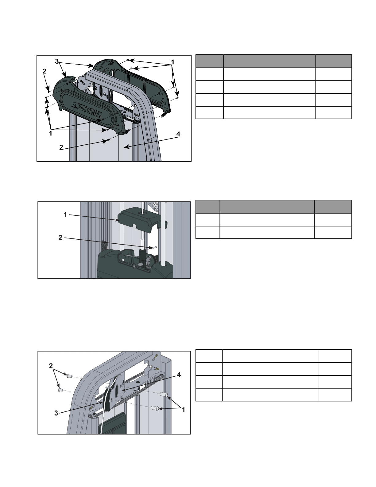
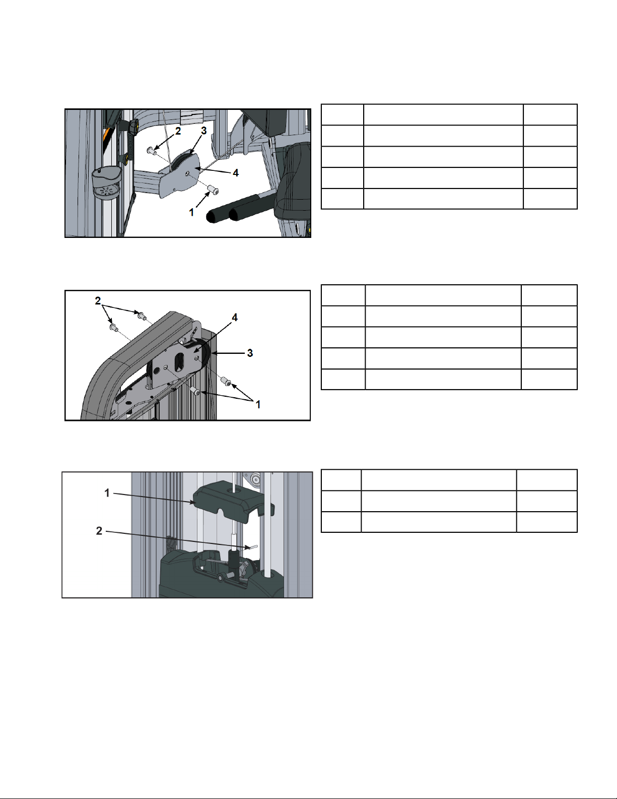
Disconnect cable
1. Make a note of the current cable routings and connections.This will assist you in reinstalling them properly.
2. Remove ten screws securing top covers (front and back) to frame using a Phillips screwdriver.
QtyDescription
810-32 screw1
2# 8 screw2
2Top cover3
1Back panel4
3. Guide front top cover down cable to gain access to pulley assembly.
4. Slide back panel upward and remove.
5. Squeeze sides of top weight cover together and lift up.
QtyDescription
1Top weight cover1
1Spiral pin2
6. Remove spiral pin connecting cable assembly using a hammer and a 3/16” pin punch.
Remove pulley assembly
1. Remove two button head socket cap screws (BHSCS) and two pulley shaft bolts securing top two pulley
assemblies to pulley bracket using two 5/16” Allen wrenches.
QtyDescription
2Pulley shaft bolt1
2BHSCS2
2Pulley assembly3
Page 11 of 25
1Pulley bracket4
2. Remove pulley assemblies from pulley bracket.
3. Remove BHSCS and pulley shaft bolts securing lower pulley assembly to pulley bracket using two 5/16” Allen
wrenches.
QtyDescription
1Pulley shaft bolt1
1BHSCS2
1Pulley assembly3
1Pulley bracket4
4. Remove pulley assembly from pulley bracket.
5. Route cable up through top cover, guide rod plate, and pulley bracket.
6. Set cable aside for rerouting.
Remove weight plates
1. Turn the increment weight adjusting knob to select 0 lbs (0 kg).
2. Remove four Phillips head screws and plastic mount for guide rod access.
QtyDescription
2Top guide rod cap1
2Guide rod2
1Guide rod plate3
4Phillips head screw4
1Plastic mount5
3. Remove top guide rod caps. Top guide rod cap contains a compression spring that will fly if grasp is not
released slowly. Slide spring loaded top guide rod cap down guide rod until cap is clear of frame. Slowly release
grasp of top guide rod cap and set aside.
4. Repeat above step for opposite guide rod.
5. Lean guide rods slightly outward, away from machine. DO NOT put excessive pressure on guide rods, it will
damage lower guide rod caps.
6. Slide top weight up and out of the machine and set aside.
7. Remove weight plates and set aside for re-installation later.
Page 12 of 25
Separate Frame
1. Remove six bolts and three connectors securing two halves of the frame using a 7/32” Allen wrench.
QtyDescription
6Bolt1
3Connector2
2. Move each half through the doorway to the desired location.
Assemble Frame
1. Apply #242 Loctite to bolts.
QtyDescription
6Bolt1
3Connector2
1# 242 Loctite3
2. Secure two halves of the frame with the six bolts and three connectors, using a 7/32” Allen wrench.
Install weight plates
1. Lean guide rods slightly outward, away from machine, DO NOT put excessive pressure on guide rods, it will
damage lower guide rod caps.
2. Wipe the entire length of the guide rods with a clean cloth.
3. Lubricate the guide rods with a light coating of medium weight oil.
Page 13 of 25
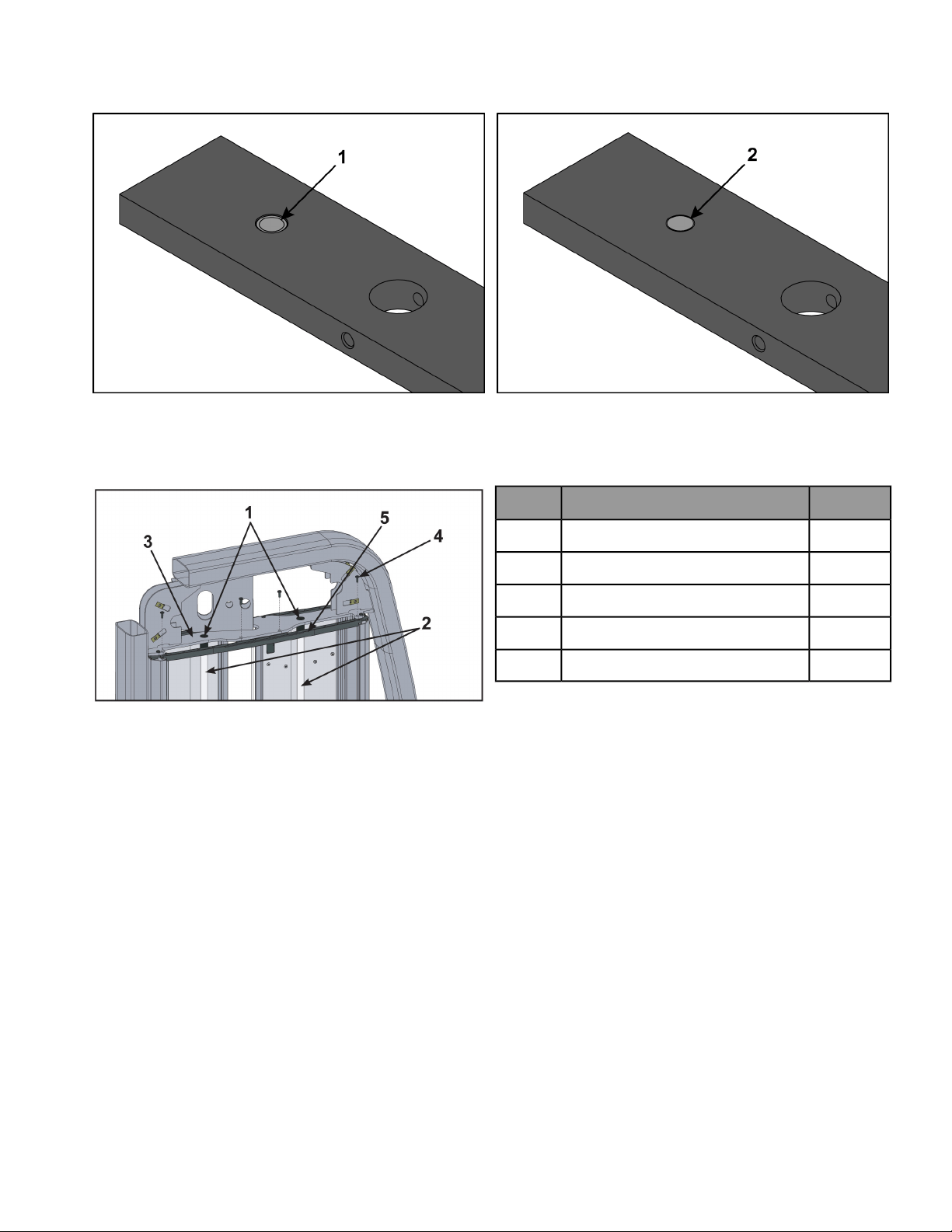
4. Install each weight plate, one at a time, so wide edge of bushing faces upward (1) and narrow edge of bushing
(2) faces downward.
Incorrect: Narrow bushing edge downward.Correct: Wide bushing edge upward
5. Slide top weight onto guide rods.
6. Install compression spring and top guide rod cap onto guide rod. Slide spring loaded top guide rod cap down
guide rod until cap is clear of guide rod plate and install. Repeat for opposite side.
QtyDescription
2Top guide rod cap1
2Guide rod2
1Guide rod plate3
4Phillips head screw4
1Plastic mount5
7. Install four Phillips head screws securing plastic mount to guide rod plate.
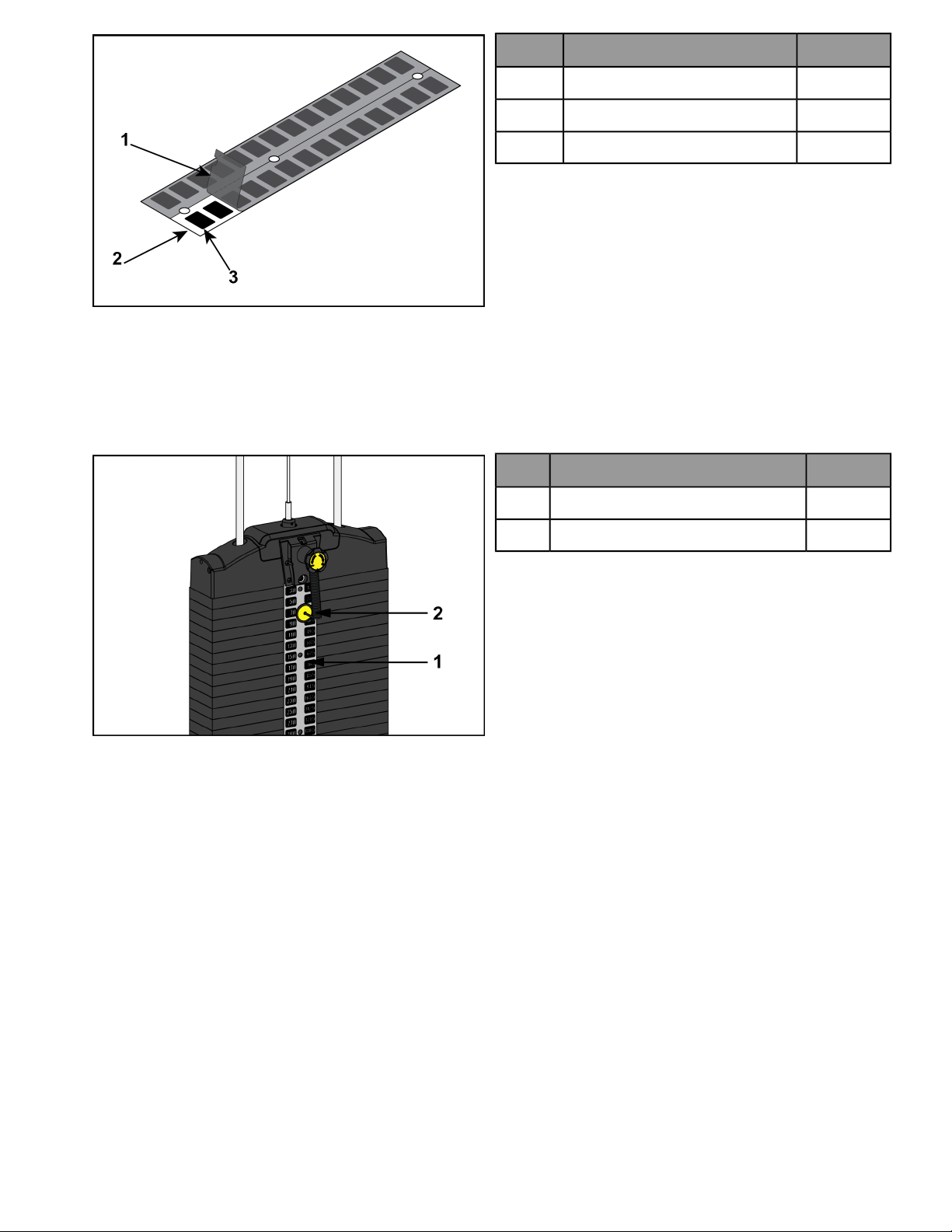
Apply weight plate decal (if not already installed on weight plates)
1. Peel off half of backing from weight plate decals, making sure that the decals remain attached to the front
sheet.
Page 14 of 25
QtyDescription
1Backing1
1Front sheet2
1Weight decals3
2. Place decals front sheet in the correct position on weight plates.
3. Insert a guide pin through each hole of the decals front sheet. (A guide pin can be anything that fits through
the weight stack hole, such as a weight stack selector pin.)
4. Align decals and rub them onto weight plates.
5. Remove front sheet, do not peel decals off of weight plates.
QtyDescription
1Weight stack selector pin1
1Weight plate decals2
6. Repeat above steps for other half of the weight plate decals.
Page 15 of 25
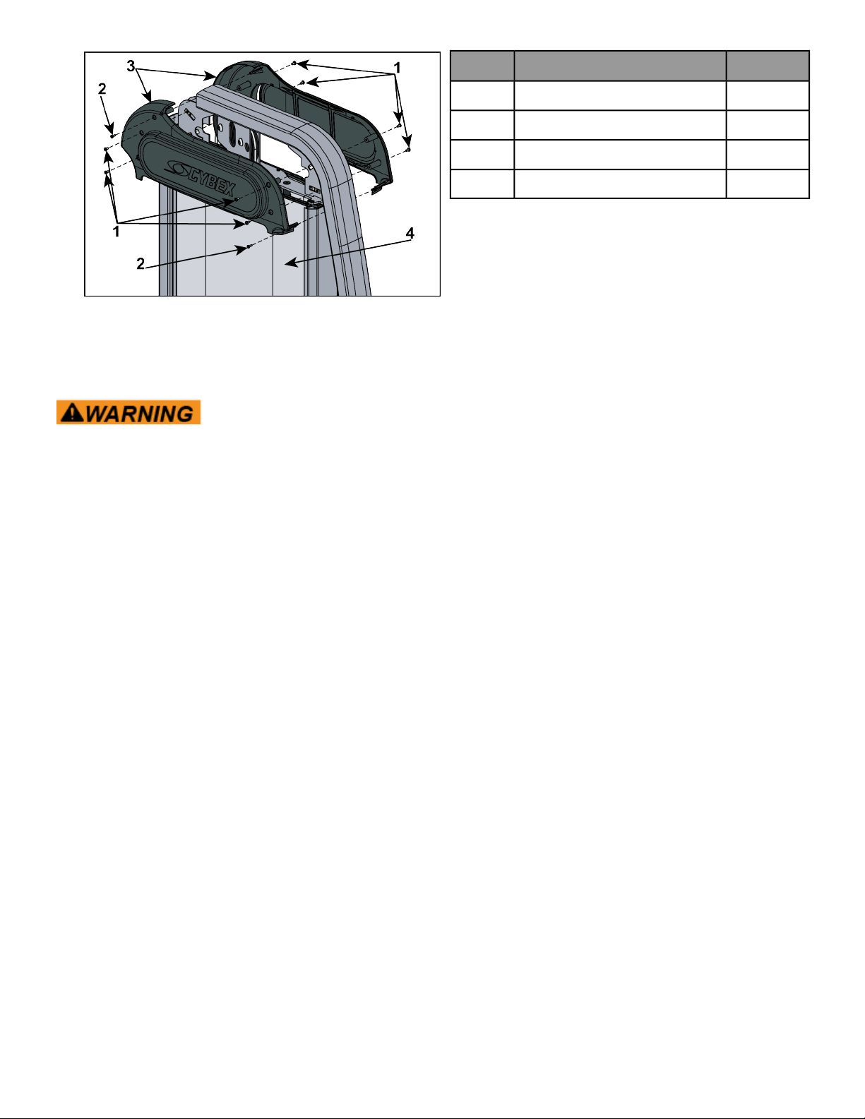
Install cable
1. Route cable through slot in top cover, through pulley bracket, and down through guide rod plate.
2. Install two BHSCS and two pulley shaft bolts securing lower pulley assembly to pulley bracket using two 5/16”
Allen wrenches.
QtyDescription
1Pulley shaft bolt1
1BHSCS2
1Lower Pulley assembly3
1Pulley bracket4
3. Install two BHSCS and two pulley shaft bolts securing top two pulley assemblies to pulley bracket using two
5/16” Allen wrenches.
QtyDescription
2Pulley shaft bolt1
2BHSCS2
2Pulley assembly3
1Pully bracket4
4. Squeeze sides of top weight cover together and lift up. Pull down on cable until it is tight. Install spiral pin
connecting cable to top weight.
QtyDescription
1Top weight cover1
1Spiral pin2
5. Verify the cable is moving smoothly.
6. Install back panel.
Page 16 of 25
7. Install ten screws securing top covers (front and back) to frame using a Phillips screwdriver.
QtyDescription
810-32 screw1
2# 8 screw2
2Top cover3
1Back panel4
Securely anchor machine to floor
Owner should not allow equipment to be used until it is properly anchored as described below.
Anchoring equipment:
• To maximize stability and eliminate rocking, tipping, or falling over, equipment
must be anchored to a solid, level surface, utilizing all anchoring holes provided.
• Fasteners must have a minimum of 500 lbs. tensile capacity. Cybex recommends
.3/8” grade 2 bolts or better. A minimum pull force of 220 lbs/100 kgs is required
for each anchor position.
• If leg frames do not contact surface, DO NOT pull down with anchors. Shim any
leg or frame not in contact with surface using flat washers.
• Due to the wide variation of flooring on which machines may be anchored or
installed, consult with a qualified and licensed contractor to ensure proper
anchoring and installation.
Verify proper operation
Page 17 of 25
Exercise
Intended Use
The intended commercial use of this machine is to aid exercise and improve general physical fitness.
Instructions
Read and understand all instructions and warnings prior to using this machine in the Safety section of the
Owner’s Manual.
Use only in manner depicted. To avoid serious injury, use equipment only as describe
in placards located on each machine.
Injuries to health may result from incorrect or excessive training.
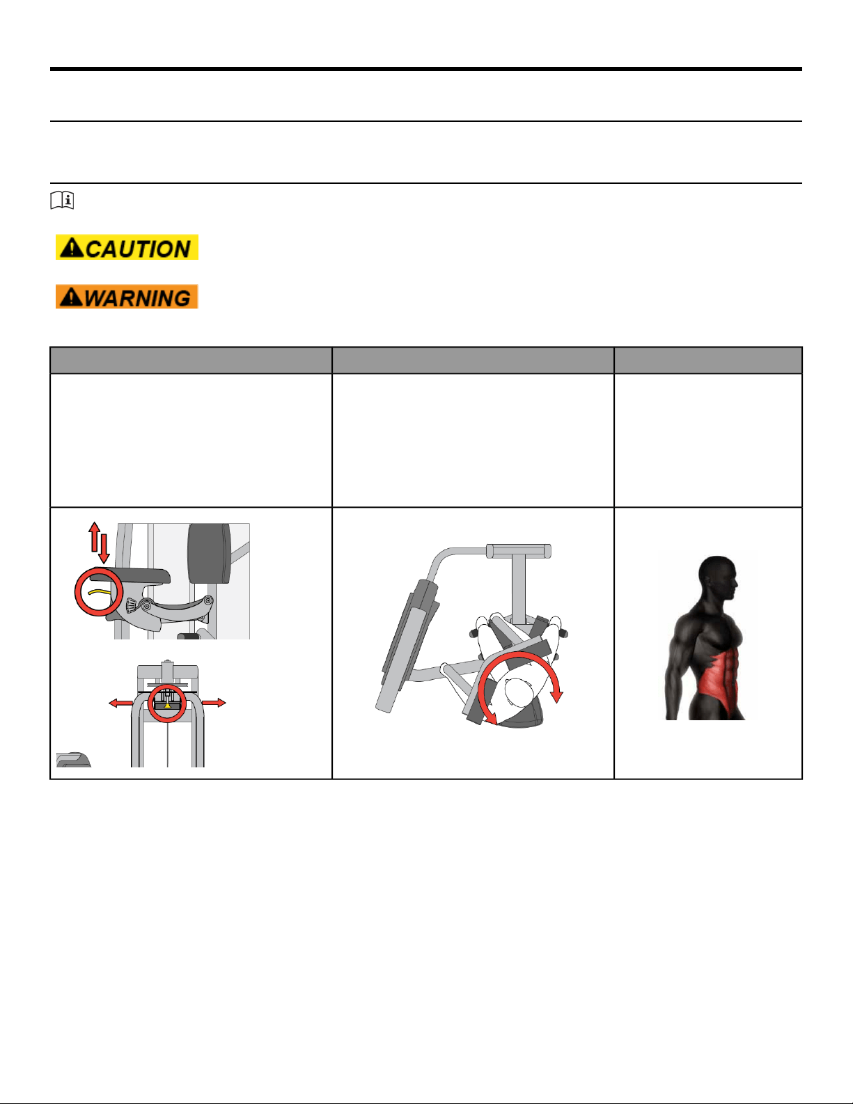
All adjustment points on the machine have yellow handles or knobs.
Muscles UsedMotionSet Up
Internal Obliques, External
Obliques, Rectus Abdominis and
Erector Spinae on same side.
Rotate upper body completely to opposite side
and return. Repeat fo opposite side.
• Adjust seat height so pads are positioned
accross upper chest..
• Select desired full left or right rotation start
position.
• Grasp handles and pull chest firmly against
pads.
• Squeeze thigh pads firmly.
Page 18 of 25

Maintenance
All preventive maintenance activities must be performed on a regular basis. Performing routine preventive
maintenance actions can aid in providing safe, trouble-free operation of all Cybex equipment.
Cybex is not responsible for performing regular inspection and maintenance actions for your machines. Instruct
all personnel in equipment inspection and maintenance actions and also in accident reporting and recording.
Cybex representatives are available to answer any questions that you may have.
Warnings
Read all warnings in this chapter.
For maintenance, service and repair:
• Must be performed by trained service personnel only
• Use only Cybex replacement parts.
Equipment hazard. To avoid serious injury or death replace worn or damaged
components immediately and keep the equipment out of use until repair is completed.
The safety level of the equipment can be maintained only if the equipment is examined
regularly for damage and wear.
Daily Procedures
When using strong cleaning agents such as rubbing alcohol or bleach, it is advisable to test first in an inconspicuous
area. Other cleaning agents may contain harsh or unknown solvents and are subject to formula changes by the
product manufacturer without notice. Should you desire to use other cleaning agents, carefully try them in an
inconspicuous area to determine potential damage to the material. Never use harsh solvents or cleaners which
are intended for industrial applications. To clean stained or soiled areas, a soft white cloth is recommended. Avoid
use of paper towels.
Cleaning products may be harmful/irritating to your skin, eyes, etc. Use protective gloves and eye protection. Do
Not inhale or swallow any cleaning product. Protect surrounding area/clothing from exposure. Use in well ventilated
area. Follow all product manufacturer’s warnings. Cybex and its vendors cannot be held responsible for damage
or injuries resulting from the use or misuse of cleaning products.
Clean Upholstery
ThenIf
Light Soiling
1. Prepare a solution of 10% household liquid soap and warm water.
2. Apply with a soft damp cloth.
3. If necessary, apply a solution of liquid cleanser with a soft bristle brush.
4. Dampen a clean soft cloth in water and wipe residue away.
More Difficult Stains
1. Prepare a solution of 10% household bleach (sodium hypochlorite) and 90% water. Dampen a soft white
cloth in the solution.
2. Rub gently on the stained area.
3. Dampen a clean soft cloth in water and rinse area.
Page 19 of 25

ThenIf
4. If stains are still present, a full strength household bleach may be used. Allow bleach to puddle on the
affected area or apply with a bleached-soaked cloth for approximately 30 minutes. Dampen a clean soft
cloth in water, and rinse area to remove any remaining bleach concentration.
More Difficult Stains
(Alternative Method)
1. Dampen a soft white cloth with rubbing alcohol.
2. Gently rub stained area.
3. Dampen a clean soft cloth in water and rinse area.
Restoring Luster
1. Apply a light coat of furniture wax for 30 seconds.
2. Lightly rub area using a clean white cloth.
Clean Frames
Wipe down all frames using a mild solution of warm water and car wash soap. Be sure to dry thoroughly. AVOID
acid or chlorine based cleaners and also cleaners containing abrasives as these could scratch or damage the
equipment.
Clean Chrome
Clean chrome tubes, first using chrome polish and then using a car wax seal. Neutral cleaners with a pH between
5.5 and 8.5 are recommended. Be sure to dry thoroughly. AVOID acid or chlorine based cleaners and also cleaners
containing abrasives as these could scratch or damage the equipment.
Guidelines for cleaning front panel:
Use clean soft cloths or sponges for application of cleaners and again for washing and rinsing. Follow up each
application with warm water rinse.
• DO NOT use abrasives or high alkaline cleaners.
• DO NOT leave cleaners on for long periods, wash immediately.
• DO NOT apply cleaners in direct sunlight or at elevated temperatures.
• DO NOT use scrapers, squeegees, or razors.
• DO NOT clean with gasoline.
Compatible Cleaners and Detergents:
• Formula 409
• Top Job
• Joy
• Palmolive
• Windex with Ammonia D
To Minimize Fine or Hairline Scratches:
Mild automotive polish applied and removed with a soft clean cloth will help fill scratches.
Suggested Polishes:
• Johnson Paste Wax
• Mirror Glaze #10 Plastic Polish (by Mirror Bright Polish Co.)
• Novus Plastics Polish #1, #2 (By Novus Inc.)
Weekly Procedures
Inspect All Nuts and Bolts
Tighten all loose nuts and bolts as required.
Equipment hazard. To avoid serious injury or death replace worn or damaged
components immediately and keep the equipment out of use until repair is completed.
Page 20 of 25

Inspect Cables
Inspect all cables for wear or damage and proper tension. When inspecting cables, run fingers on the cable, paying
particular attention to bends and attachment points.
The following conditions may indicate a worn cable:
DiagramCondition of Cable
A tear or crack in the cable
sheath that exposes the
cable
A kink in the cable
A curled sheath
Necking - A stretched
cable sheath
Inspect Other Items
Inspect other items for proper operation, damage, or wear.
ActionInspection
Replace all loose or worn grips immediately.Inspect grips for looseness or wear.
Replace all worn labeling immediately.
Inspect all labeling for readability, including instructional placards,
warning and caution decals.
Correct all improper alignment and operation issues immediately.Inspect all weight stacks for proper alignment and operation.
Wipe Weight Stack Guide Rods clean over entire length. Lubricate
with a light coat of medium weight automotive engine oil.
Inspect guide rods for lubrication.
Yearly Procedures
Replace all cables and belts annually
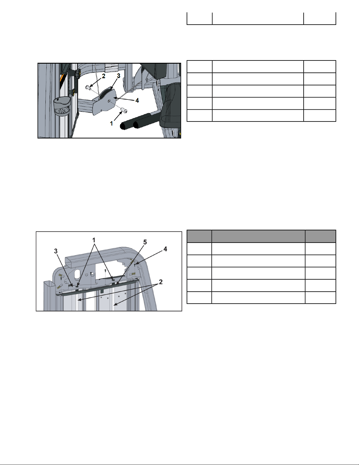
Cable Adjustment
Tools Required
9/16" Wrench (2)
Four types of cable tension adjustment are used on Cybex Strength Systems:
Jam Nut Adjustment
This type of adjustment uses a jam nut and a tension adjustment nut at the cable cam end as the primary
adjustment. The other end of the cable usually contains a roll pin adjustment.
Page 21 of 25
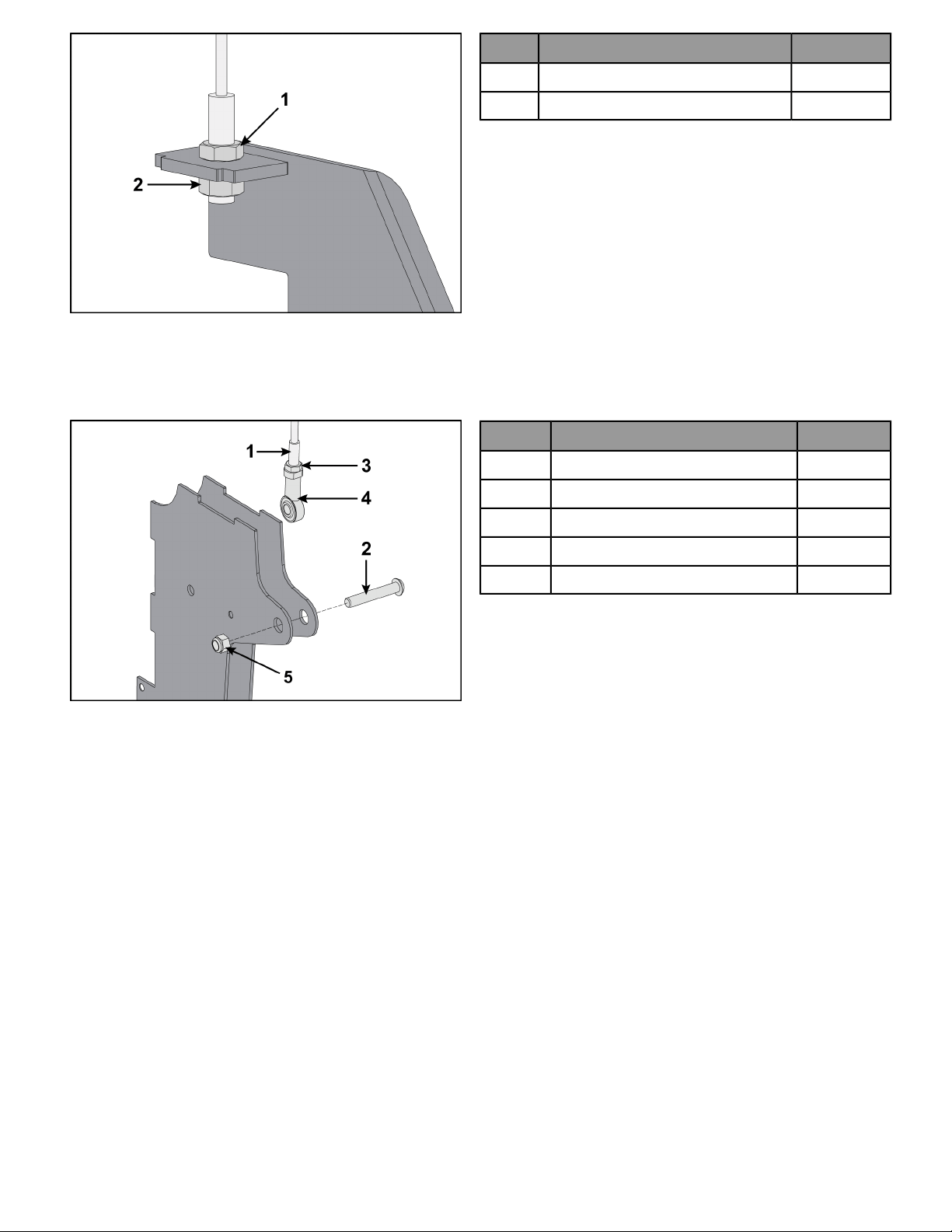
Qty.Description
1Jam nut1
1Tension adjustment nut2
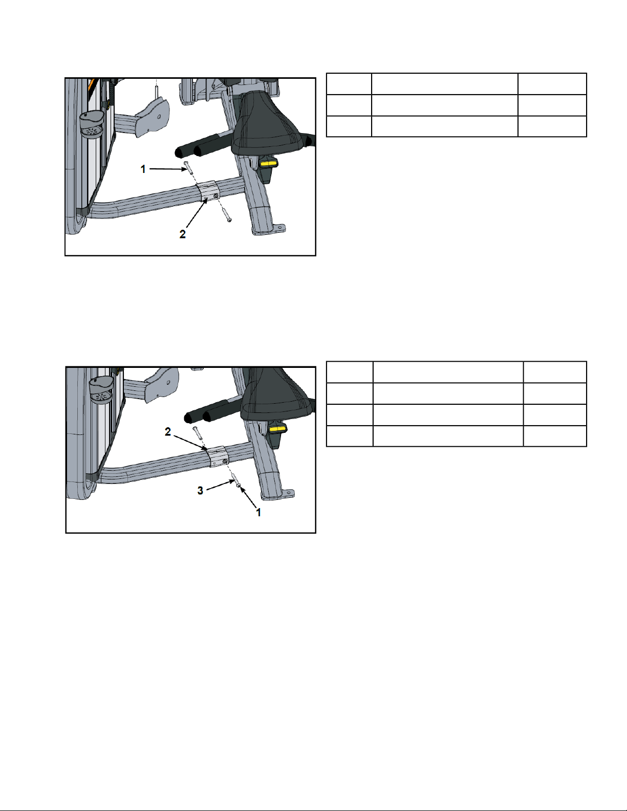
Rod End Adjustment
This type of adjustment uses a socket head cap screw (SHCS) securing a cable rod end bearing to the machine.
Primary adjustment is by turning the rod end bearing. The other end of the cable usually contains a roll pin cable
adjustment.
Qty.Description
1Cable end1
1SHCS2
1Jam nut3
1Cable rod end bearing4
1Nylon locknut5
Page 22 of 25

Customer Service
Product Registration
To register product do the following:.
1. Visit www.cybexintl.com.
2. Locate Product Registration in the Support section.
3. Fill out form completely.
4. Click the Submit button to register product.
Contacting Service
Hours of phone service are Monday through Friday from 8:30 a.m. to 6:00 p.m. Eastern Standard Time.
For Cybex customers living in the USA, contact Cybex Customer Service at 1-888-462-9239.
For Cybex customers living outside the USA, contact Cybex Customer Service at 1-508-533-4300 or fax 1-508-533-5183.
Find information on the web at www.cybexintl.com.
To contact us online go to www.cybexintl.com.
Ordering Parts
To order parts online go to www.cybexintl.com.
To speak with a customer service representative, call 800-351-3737 (for customers living within the USA) or
847-288-3700 (for customers outside the USA).
The following information located on the serial number decal will assist our Cybex representatives in serving you.
• Unit Serial Number, Product Name and Model Number
• Part Description and Part Number if you have it. All parts can be found on the web at www.cybexintl.com
• Shipping Address
• Contact Name
• Include a description of the problem.
In addition to your shipping address and contact name, your account number is helpful but not required. You may
also fax orders to 800-216-8893.
Return Material Authorization (RMA)
The Return Material Authorization (RMA) system is used when returning material for placement, repair or credit.
The system assures that returned materials are properly handled and analyzed. Follow the following procedures
carefully.
Contact your authorized Cybex dealer on all warranty-related matters. Your local Cybex dealer will request a RMA
from Cybex, if applicable. Under no circumstances will defective parts or equipment be accepted by Cybex without
proper RMA and an Automated Return Service (ARS) label.
Please contact Cybex Customer Service for the return of any item that is defective.
Page 23 of 25

Provide the technician with a detailed description of the problem you are having or the defect in the item you wish
to return. Provide the model and serial number of your Cybex equipment.
At Cybex’s discretion, the technician may request that you return the problem part(s) to Cybex for evaluation and
repair or replacement. The technician will assign you a RMA number and will send you an ARS label. The ARS label
and the RMA numbers must be clearly displayed on the outside of the package that contains the item(s) to be
returned. Include the description of the problem, the serial number of the equipment and the name and address
of the owner in the package along with the part(s).
Merchandise returned without an RMA number on the outside of the package or shipments sent COD will not be
accepted by the Cybex receiving department.
Damaged Parts
Materials damaged in shipment should not be returned for credit. Shipping damages are the responsibility of the
carrier (UPS, Federal Express, trucking companies, etc.)
Apparent Damage
Upon receipt of your shipment, check all items carefully. Any damage seen with a visual check must be noted on
the freight bill and signed by the carrier’s agent. Failure to do so will result in the carriers refusal to honor your
damage claim. The carrier will provide you with the required forms for filing such claims.
Concealed Damage
Damage not seen with a visual check upon receipt of a shipment but notices later must be reported to the carrier
as soon as possible. Upon discovery of the damage, a written or phone request to the carrier asking them to
perform an inspection of the materials must be made within ten days of the delivery date. Keep all shipping
containers and packing materials as they will be needed in the inspection process. The carrier will provide you
with an inspection report and the necessary forms for filing a concealed damage claim. Concealed damage claim
is the carrier’s responsibility.
Page 24 of 25


Columbia Center III - 9525 West Bryn Mawr Ave, Rosemont, IL 60018 • 800-351-3737 • 847-288-3700 • FAX 800-216-8893
www.cybexintl.com