Please read this entire manual carefully
before operating your new treadmill
and save it for future use.
User manual
Register your product and get support at
www.philips.com/welcome
PTE4000CT
ReActiv
Treadmill
4.0 T
Register your product and get support at
www.philips.com/welcome

Thank you for your recent purchase of the Philips physical rehabilitation
treadmill 4.0 T.
Philips physical therapy and exercise solutions provide simple, reliable
products that oer the most relevant feedback to caregivers and users
to achieve best-in-class outcomes and empower individuals to build
condence in rebuilding and maintaining healthy lifestyles and keep in
touch with their communities.
Your new product has been manufactured by one of the world’s leading
medical product manufacturers. It is backed by one of the most
comprehensive warranties in the industry. Through our dealers,
distributors and manufacturer’s representatives, we will do all we can to
provide many years of successful and prosperous ownership. Your
warranty and service needs will be addressed either through your
regional sales representative or our highly trained service technicians.
It is their responsibility to provide you with both the technical
knowledge and access to service personnel to make your
ownership experience more informed, and resolve any issues
quickly.
Product registration
Register your product and get support at:
www.philips.com/welcome .
This will ensure we have all your details quickly at hand in dealing with
any after sales support. For fastest support visit us and self service
solution at :
www.philips.com/support
Philips therapy solutions
Delivering better outcomes

Contents
Important safety instructions 4
Important electrical information
Important operation instructions 8
Features 9
Assembly instructions 10
Console operation 17
6
Using a heart rate transmitter 40
Maintenance 43

4
Attention
Read all instructions in this manual before using this device.
Danger
To reduce the risk of electric shock disconnect this device from the
electrical outlet prior to cleaning and/or service work.
Warning
• Before beginning exercise on this product, or any exercise program,
consult a physician. This is especially important for persons over the
age of 35 or persons with preexisting health conditions.
• There are obvious pinch points and other caution areas that can
cause harm.
• Children under the age of 13 should be supervised to ensure that they
do not play with the device.
• Keep hands away from all moving parts.
• Never drop or insert any object into any openings.
• Do not use outdoors.
• Do not operate under a blanket or pillow. Excessive heating can
occur and cause fire, electric shock, or injury to persons.
• Do not attempt to use this product for any purpose other than for
the purpose it is intended.
• Do not operate where aerosol (spray) products are being used or
where oxygen is being administered. Sparks from the motor may
ignite a highly gaseous environment.
Important
safety
instructions

5
• Never operate the product if it has a damaged cord or plug, if the
product is not working properly, call your dealer. If it has been
dropped or damaged, or dropped into water, call your dealer.
• Keep the cord away from heated surfaces.
• The hand pulse sensors are not medical devices. Various factors,
including the user’s movement, may aect the accuracy of heart rate
readings. The pulse sensors are intended only as an exercise aid in
determining heart rate trends in general.
• Heart rate monitoring systems may be inaccurate. Over exercising
may result in serious injury or death. If you feel faint stop exercising
immediately.
• Wear proper shoes. High heels, dress shoes, sandals or bare feet are
not suitable for use on your treadmill. Quality athletic shoes are
recommended to avoid leg fatigue.
• The product should never be left unattended when plugged in.
Unplug from outlet when not in use and before putting on or taking
o parts.
• Connect the product to a properly grounded outlet only. See
Grounding Instructions.
• This appliance is not intended for use by persons with reduced
physical, sensory or mental capabilities, or lack of experience and
knowledge, unless they have been given supervision or instruction
concerning use of the appliance by a person responsible for their
safety.
• Maximum User Weight: 450 lbs,
• ASTM F2115-05 Specifications 6.1.2.11—The recommended minimum
clearance required around each treadmill for access to, passage
around, and emergency dismount shall be stated. The minimum
dimensions are to be: 0.5 m (19.7 in.) on each side of the treadmill,
and 1m (39 in.) behind the machine.

6
Warning
• Never use a ground fault circuit interrupter (GFCI) wall outlet with
this treadmill. As with any appliance with a large motor, the GFCI
will trip often. Route the power cord away from any moving part of
the treadmill including the elevation mechanism and transport
wheels.
• Never remove any cover without first disconnecting AC power. If AC
voltage varies by 10% or more outside of specified range (90 to
120V), the performance of your treadmill may be affected. Such
conditions are not covered under your warranty. If you suspect the
voltage is low, contact your local power company or a licensed
electrician for proper testing.
• Never expose this product to rain or moisture. This product is not
designed for use outdoors, near a pool or spa, or in any other high
humidity environment. The operating temperature specication is 5
to 48 degrees Celsius (40 to 120 degrees Fahrenheit)and humidity is
95% non-condensing (no water drops forming on surfaces).
• Circuit Breakers: Some circuit breakers are not rated for high inrush
currents that can occur when a treadmill is rst turned on or even
during use. If your treadmill is tripping the circuit breaker (even
though it is the proper current rating) but the circuit breaker on the
treadmill itself does not trip, you will need to replace the facility
breaker with a high inrush type. This is not a warranty defect. This is
a condition we as a manufacturer have no ability to control. This
part is available through most electrical supply stores. The electrical
outlet used should have a dedicated 20-amp circuit breaker.
Important
electrical
information

7
Grounding instructions
This product must be grounded. In the unlikely event that the
treadmill’s electrical system should malfunction or break
grounding provides a path of least resistance for electric current,
reducing the risk of electric shock. This product is equipped with a
cord having an equipment-grounding plug. The plug must be
plugged into an appropriate outlet that is properly installed and
grounded in accordance with all local codes and ordinances.
Danger
Improper connection of the equipment-grounding conductor can
result in a risk of electric shock. Check with a qualied electrician or
serviceman if you are in doubt as to whether the product is properly
grounded. Do not modify the plug provided with the product if it will
not t the outlet. Instead have a proper outlet installed by a
qualied electrician.

8
• Never operate this product without reading and completely
understanding the results of any operational change you request from
the console.
• Understand that changes in speed or incline do not occur immediately.
Set your desired speed or incline level on the console and release the
adjustment key. The console will obey the command gradually.
• Use caution while participating in other activities while on your
Treadmill; such as watching television, reading, etc. These distractions
may cause you to lose balance which may result in serious injury.
• Do not use excessive pressure on console control keys. They are
precision set to function properly with little nger pressure.
Safety tether cord
A safety tether cord is provided with this unit. It is a simple magnetic
design that should be used at all times. It is for your safety should you
fall or move too far back on the treadbelt. Pulling this safety tether cord
will stop treadbelt movement. To use:
• Place the magnet into position on the round metal portion of the
console control head. Your treadmill will not start and operate without
this. Removing the magnet also secures the treadmill from
unauthorized use.
• Fasten the plastic clip onto your clothing securely to assure good
holding power. Note: The magnet has strong enough power to
minimize accidental, unexpected stopping. The clip should be
attached securely to make certain it does not come o. Be familiar
with its function and limitations. The treadmill will stop, depending on
speed, with a one to two step coast anytime the magnet is pulled o
the console. Use the Stop / Pause switch in normal operation.
Important
operation
instructions
9
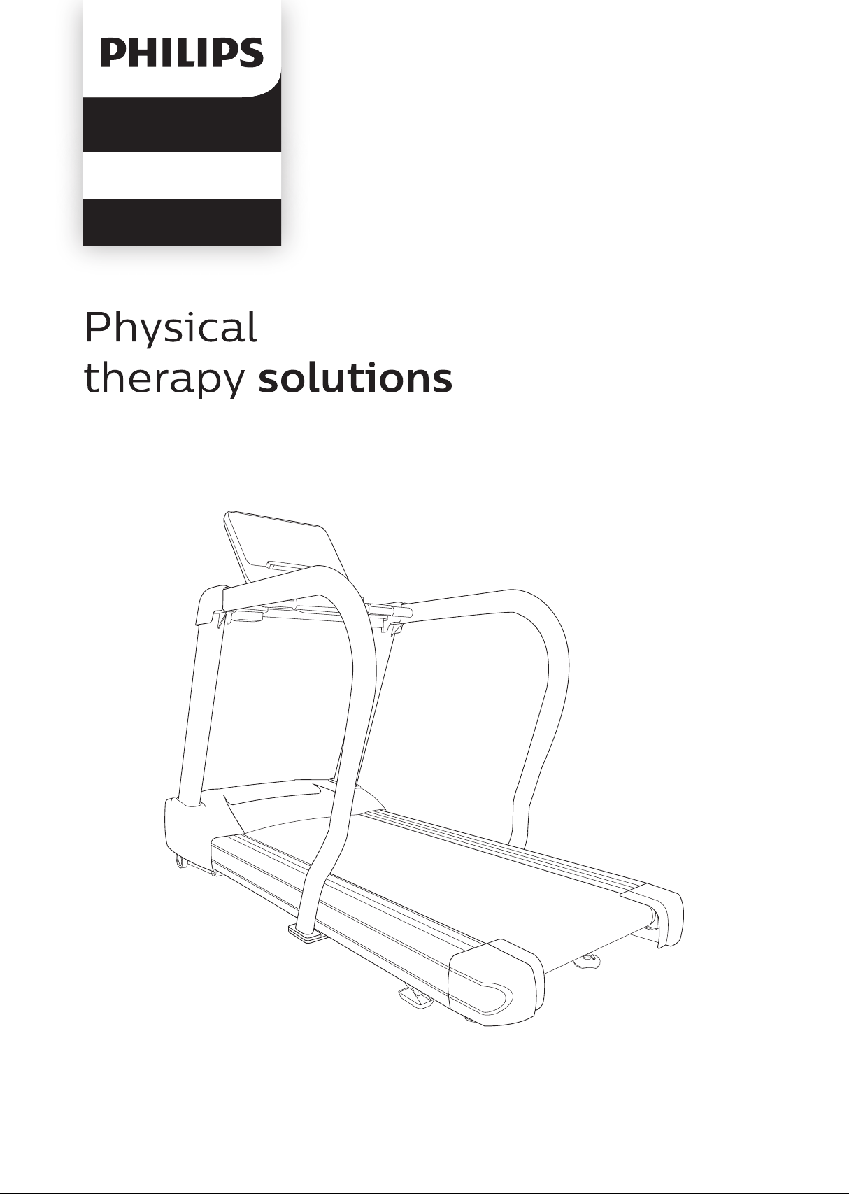
4.0 T – Treadmill
Parts and adjustments
1. Console
2. Handlebar with heart rate grips
3. Safety tether cord placement
4. Water bottle holder
5. Extended handrails
6. Console mast
7. Motor cover
8. Belt
9. Side rail
10. Tracking / Tension adjustment bolts
Features
6
7
8
9
10
2
3
4
5
1

1010
Unpacking
• Cut the straps, then lift the box over the unit and unpack.
• Carefully remove all parts from the carton and inspect for any damage
or missing parts. If parts are damaged or missing, contact your dealer
immediately.
• Locate the hardware package. Remove the tools first. Remove the
hardware for each step as needed to avoid confusion. The numbers in
the instructions that are in parenthesis (#) are the item number from
the assembly drawing for reference.
Tools included
• 5mm L Allen Wrench
• 6mm L Allen Wrench
• 1 Phillips Screwdriver
Assembly
instructions
Parts included
• 1 Main Frame
• 2 Console Mast
• 1 Main Panel
• 1 Console
• 1 Console Bracket Cover
• 4 Handrail Cover
• 2 Console Mast Cover
• 2 End Caps
11
Part Type Description
Hardware for step 1
Qty
128
129
130
Bolt
Flat washer
Split washer
3/8" × 3"
Ø3/8” × Ø35 x 2T
Ø10 × 2.0T
6
10
10
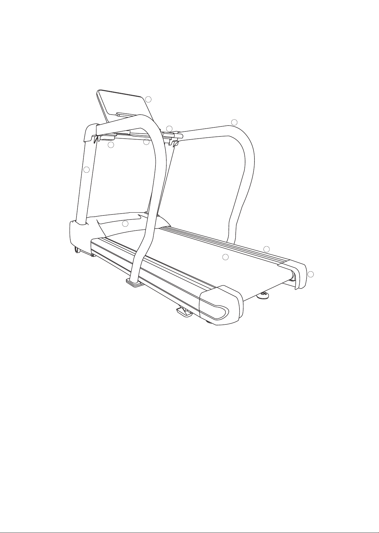
Assembly
Read each step’s instructions and study the drawing carefully to become
familiar with all the parts and procedures before beginning each step.
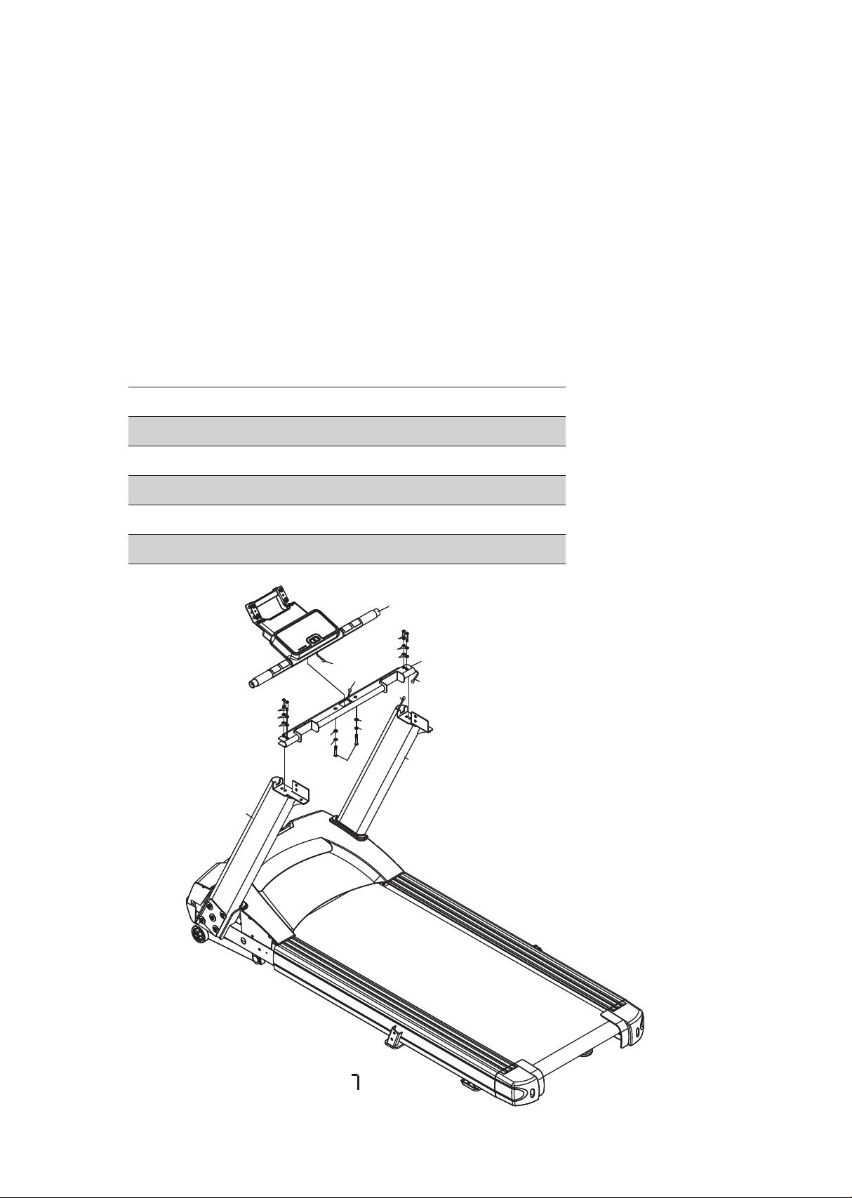
Step 1.
• Attach one Fixing Plate (66) and Left Console Mast (33) to Frame (1)
using five Bolts (128), five Split Washers (130), and five Flat Washers
(129). Do not tighten before putting the console on.
• Connect Wires (41) from the Right Console Mast (34) with another
Wires (178 ) from the Frame (1). Then attach another Fixing Plate (66)
and Right Console Mast (34) to Frame (1) using five Bolts (128), five
Split Washers (130), and five Flat Washers (129). Do not pinch Wires
(41 & 178). Do not tighten before putting the console on.
33
66
128
129
130
128
130
129
128
130
129
34
66
129
130
128
129
130
128
129
130
128
41
142
178
12
Step 2.
• Connect Wires (41) with Handle Bar Wires (36A) from Handle Bar Frame
(5). Do not pinch Wires (41 & 36A).
• Install Handle Bar Frame (3) onto the console masts using Bolts (131),
Split Washers (130) and Flat Washers (166). Do not tighten before
putting the console on.
• Connect Wires (40) from Lower Console Assembly (3) with Handle Bar
Wires (36A).
• Install Lower Console Assembly (3) onto Handle Bar Frame (3) using
Bolts (167), Split Washers (130) and Flat Washers (166). Do not tighten
before putting the console on.
Part
130
131
166
167
Split washer
Bolt
Flat washer
Bolt
Type Description
Hardware for step 2
Qty
Ø10 × 2.0T
M8 × 45mm
Ø8.5 × Ø16 × 1.5T
M8 × 50mm
6
4
6
2
131
130
166
167
130
166
130
166
166
5
131
130
3
141
41
36(A)
40
36(B)
33
34

13
Part Type Description
Hardware for step 3
Qty
130
131
132
133
135
137
138
166
Split washer
Bolt
Bolt
Curved washer
Bolt
Bolt
Flat washer
Flat Washer
Ø10 × 2.0T
M8 × 45mm
M8 × 80mm
Ø10 × Ø23 × 1.5T
M8 × 20mm
M8 × 35mm
Ø5/16" × Ø23 × 1.5T
Ø8.5 × Ø16 × 1.5T
8
4
4
2
4
2
2
8
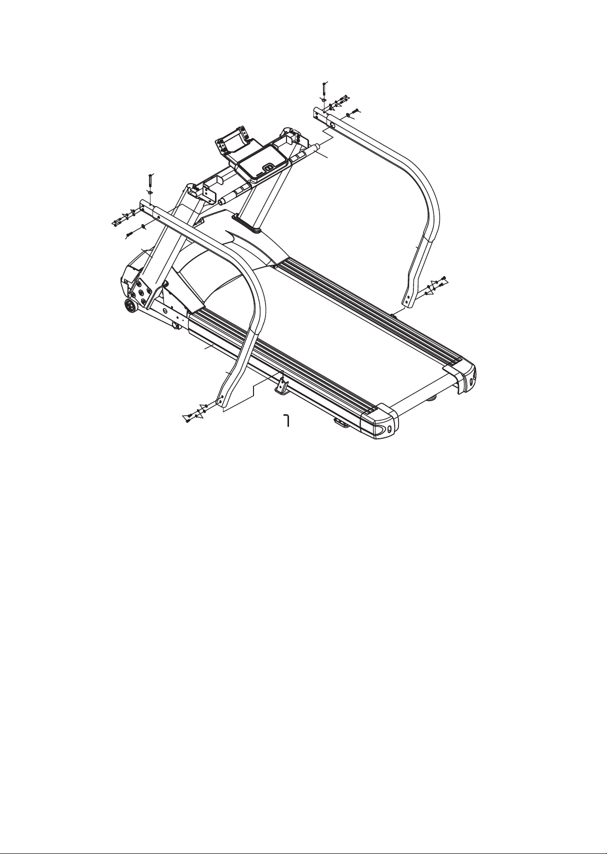
Step 3.
• Attach Left Handrail (74) onto Frame (1) and Lower Console Assembly
(3), at the top area using two Bolts (131), two Split Washers (130), two
Flat Washers (166), one Bolt (132) and one Curved Washer (133), at the
bottom area using two Bolts (135), two Split Washers (130) and two Flat
Washers (166). Do not tighten before putting both handrails on.
• Attach Right Handrail (74) onto Frame (1) and Lower Console Assembly
(3), at the top area using two Bolts (131), two Split Washers (130), two
Flat Washers (166), one Bolt (132) and one Curved Washer (133), at the
bottom area using two Bolts (135), two Split Washers (130) and two Flat
Washers (166).
• Tight all bolts and washers from previous step.
14
75
135
130
166
131
130
137
132
133
138
166
74
137
135
130
166
131
130
132
133
138
166
141
3
1
33
15
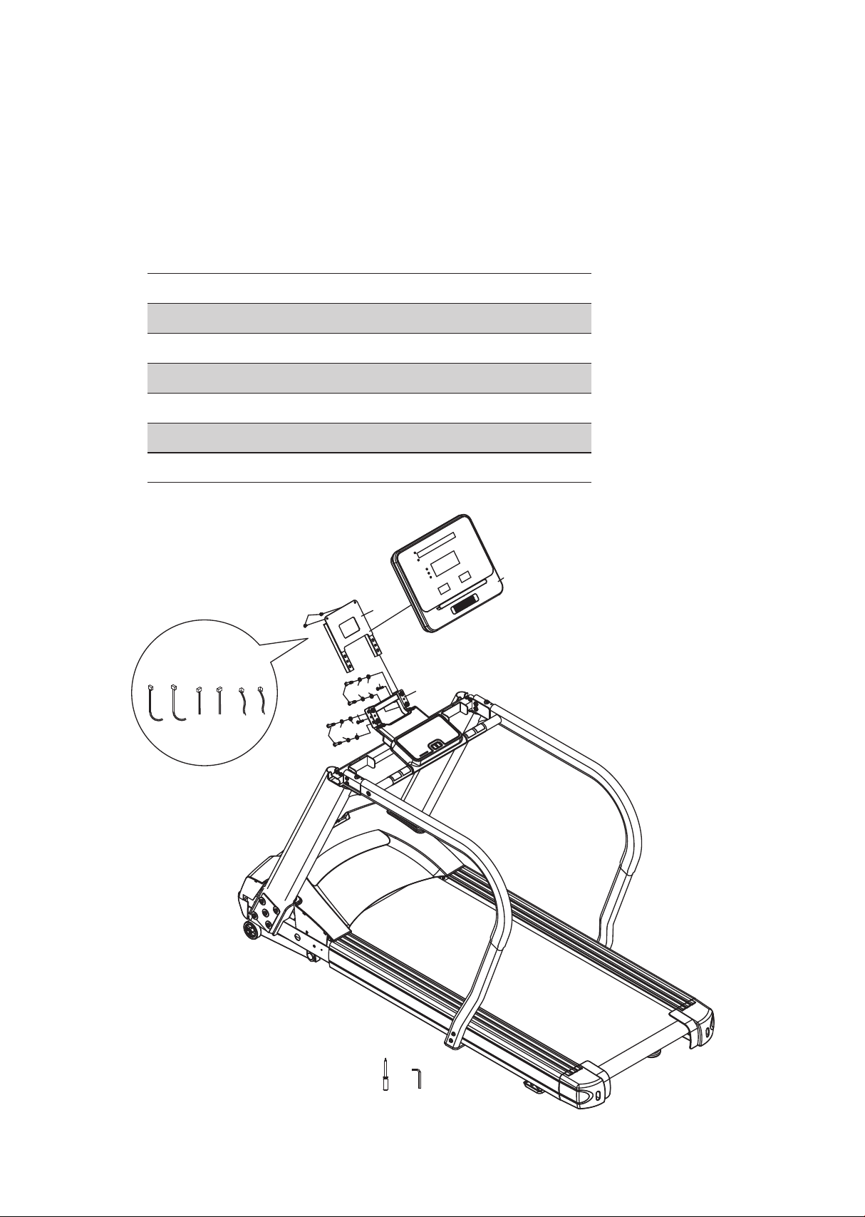
Step 4.
• Attach Console Frame (4) on Lower Console Assembly (3) using four
Bolts (131), four Split Washers (130) and four Flat Washers (166).
• Connect the Wiring Harness (35、37、38、39、40、58) with Console
(28), attach Console (28) on Console Frame (4) using two Screws (116),
and two Screws (134).
Part Type Description
Hardware for step 4
Qty
116
130
131
134
166
Screw
Split washer
Bolt
Screw
Flat washer
M5 × 12mm
Ø10 × 2.0T
M8 × 45mm
M5 × 40mm
Ø8.5 × Ø16 × 1.5T
6
6
2
2
2
4
28
131
131
166
166
116
134
134
130
130
143
141
38
37
40
58
39
35
3
16
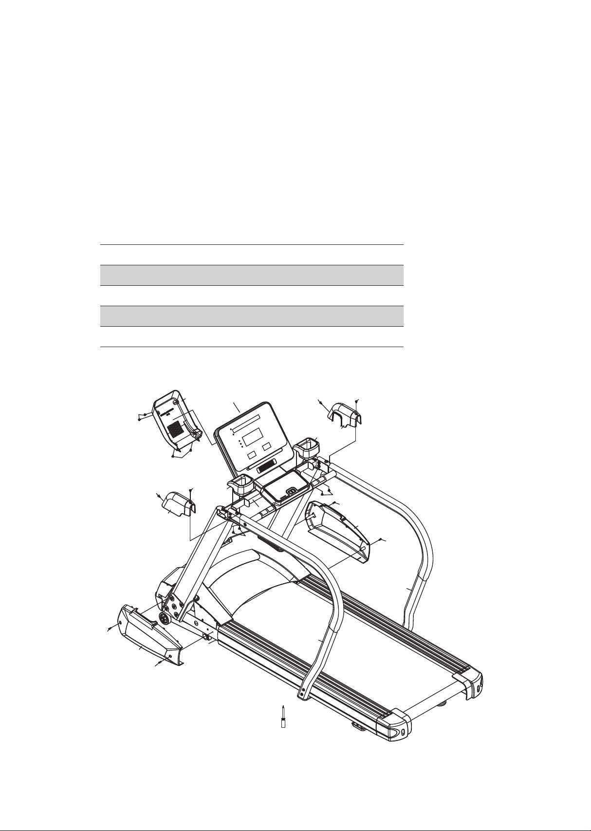
Step 5.
• Attach Right & Left Lower Console Mast (26 & 27) on Frame (1) using
four Screws (116) (Black).
• Attach Right & Left Upper Console Mast (64、65) on Right & Left
Handrail (74、75) using four Screws (136) (Silver).
• Attach Bottle Holder (31) on Handle Bar Frame (5) using four Tapping
Screws (140 ).
• Attach Console Back Cover (32) on Console Frame (4) using four Screws
(116).
Part Type Description
Hardware for step 5
Qty
116
136
140
Screws
Screws
Tapping screws
M5x 12mm
M5x 12mm
M5x 10mm
8
4
4
143
64
136
136
65
136
136
27
116
116
26
116
116
32
116
116
140
140
31
31
1
74
75
5
4
17
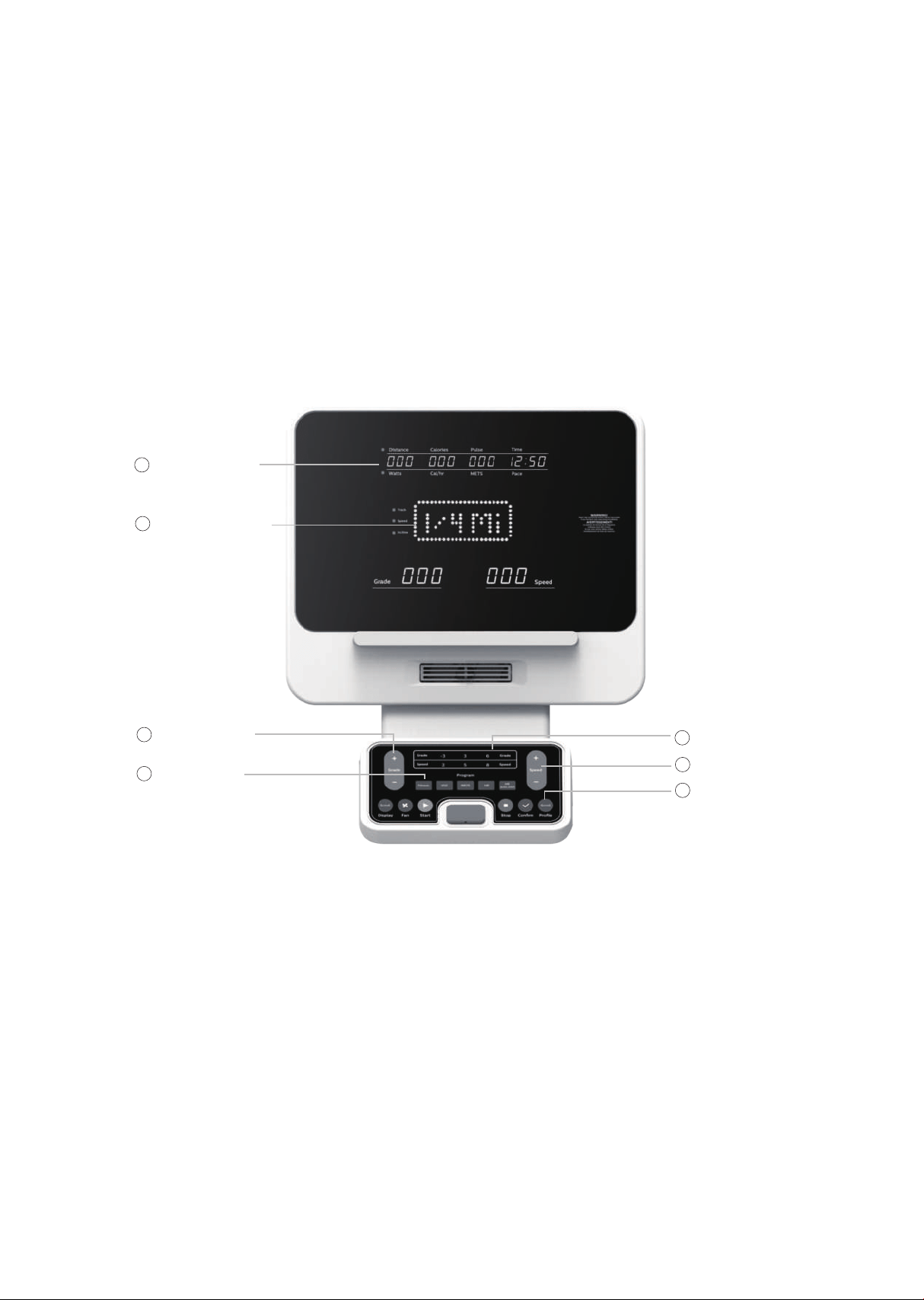
4.0 T Console
Power on
Power the treadmill on by plugging it into an appropriate wall outlet,
then turn on the power switch located at the front of the treadmill
below the motor hood. Ensure that the safety key is installed, as the
treadmill will not power on without it.
When the power switch is turned on the console will go to the start
up display, also known as Idle Mode. The Message Window will be
scrolling the start up message. You may now begin to use the 4.0 T.
Console
operation
Message window
1
Program keys
4
Incline/Decline
keys
3
Quick Keys
5
Speed Keys
6
Function Keys
7
2
Dot matrix window

18
CSAFE feature
Your console is equipped with a CSAFE feature. The Power (POWER)
port can be used for powering a remote controlled audio-visual system
by connecting a cable from the remote to the Power port at the back of
the console. The Communication port (COMM) can be used to interact
with software applications.
Quick start
This is the quickest way to start a workout. After the console powers up
you just press the Start key to begin. This will initiate the Quick Start
mode. In Quick Start, the Time will count up from zero, all workout data
will start to accrue and the workload may be adjusted manually by
pressing the Plus and Minus keys. As you increase the workload more
rows will light indicating a harder workout.

19
Basic information
When you begin a program the dot matrix will display the workout
Prole.
The Message Window will initially be displaying distance, calories, pulse
and time information. On the bottom left of the lower keypad is a key
labeled Display. Each time this Display key is pressed the next set of
information will appear. If the Display key is pressed during the second
set of information display the Scan mode will come on and the Message
Window will show each set of data for four seconds then switch to the
next set of data in a continuous loop. Pressing the Display key again will
bring you back to the rst set of information as beginning.
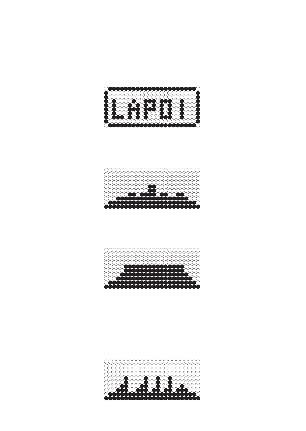
The dot matrix window is used for displaying graphic feedback and has
three basic displays for most programs. When you begin a program the
dot matrix window will display a speed profile. On the bottom right of
the lower keypad is a key labeled Prole. Pressing this key will switch the
display to show an incline grade and then a track. When the LEDs are
blinking the graph will scan through the three displays.
The product has a built in heart rate monitoring system. Simply grasping
the hand pulse sensors, or wearing a heart rate chest belt transmitter
will start the heart rate detection, The Message Window will display your
heart rate, or Pulse, in beats per minute (this may take a few seconds).
NOTE: You must enter your correct age during program setup for heart
rate control program to be accurate. Refer to Using a Heart Rate trans-
mitter section for details about these features and how they can help
you work out more eciently.
The Stop key actually has several functions. Pressing the Stop key once
during a program will pause the program for 5 minutes. If you need to
get a drink, answer the phone, or any of the many things that could
interrupt your workout, this is a great feature. To resume your workout
during Pause just press the Start key. If the Stop key is pressed twice
during a workout the program will end and a summary of information of
the exercise session will be displayed, and then the console will return
to the start up screen. If the Stop key is held down for 3 seconds the
console will perform a complete Reset. During data entry for a program
the Stop key performs a Previous Screen function. This allows you to go
back one step in the programming each time you press the Stop key.

20
The program keys may be used to preview each program when in the
idle mode. When you first turn the console on you may press each
program key to preview what the program prole looks like. If you
decide that you want to try a program, press the corresponding
program key and then press the Conrm key to select the program
and enter into the data-setup mode.
The console includes a built-in fan to help keep you cool.
Programmable features
Each of the programs can be customized with your personal
information and changed to suit your needs. Some of the information
asked for is necessary to ensure the readouts are correct. You will be
asked for your Age and Weight. Entering your Age ensures that the
Heart Rate window shows the correct number. Your Age is also
necessary during the Heart Rate control program to ensure the correct
settings are in the program for your Age. Otherwise the work settings
could be too high or low for you; entering your Weight aides in
calculating a more correct Calorie reading. Although we cannot provide
an exact calorie count we do want to be as close as possible.
CALORIE NOTE: Calorie readings on every piece of exercise equipment,
whether it is in a facility or at home, are not accurate and tend to vary
widely. They are meant only as a guide to monitor your progress from
workout to workout. The only way to measure your calorie burn
accurately is in a clinical setting connected to a host of machines.
This is because every person is dierent and burns calories at a
dierent rate. Some good news is that you will continue to burn calories
at an accelerated rate for at least an hour after you have nished
exercising!

21
Entering a program and changing settings
When you enter a program (by pressing a program key, then Confirm
key) you have the option of modifying the settings. If you want to
begin without entering new settings just press the Start key. This will
bypass the programming of data and take you directly to the start of
the program. If you want to change the settings just follow the
instructions in the Message Window. If you start a program without
changing the settings the default or pre-saved setting will be used.
Manual
The Manual program works as the name implies, manually. This
means that you control the workload yourself, not the computer. To
start the Manual program follow the instructions below or just press
the Manual key then the Conrm key and follow the directions in the
Message Window.
• Press the Fitness key and select the Manual program then press the
Conrm key.
• The Message Window will ask you to enter your Age. You may enter
your Age, using the Plus and Minus keys, then press the conrm button
to accept the new number and proceed on to the next screen.
• You are now asked to enter your Weight. You may adjust the Weight
number using the Plus and Minus keys, then press conrm to continue.
• The next setting is Time. You may adjust the Time and press Confirm
key to continue.
• Now you are finished editing the settings and can begin your workout
by pressing the Start key. You can also go back and modify your set-
tings by pressing the Conrm key.
Note: At any time during the editing of data you can press the Stop key
to go back one level, or screen.
• During the Manual program you will be able to scroll through the data
in the Message Window by pressing the Display key.
• When the program ends you may press Start to begin the same
program again or Stop to exit the program

22
Preset programs
The treadmill has four dierent programs that have been designed for a
variety of workout goals. These programs factory preset work level
proles for achieving dierent goals. The initial built-in level of diculty
for each program is set to a relatively easy level. You may adjust the
level of difficulty (Max speed) for each program before beginning.
Programming preset programs
• Select the desired program by pressing Fitness key then press Confirm
key.
• The Message Window will ask you to enter your Age. You may adjust
the age setting, using the Plus and Minus keys, then press Conrm key
to accept the new number and proceed on to the next screen.
• You are now asked to enter your Weight. You may adjust the weight
number using the Plus and Minus keys, then press Conrm to continue.
• Next is Time (excluding the 5K program). You may adjust the Time and
press Conrm to continue.
• Now you are asked to adjust the Max Speed. This is the peak exertion
level you will experience during the program. Adjust the speed and
then press Conrm.
• Now you are finished editing the settings and can begin your workout
by pressing the Start key. You can also go back and modify your
settings by pressing the Stop key to go back one level, or screen.
• If you want to increase or decrease the workload at any time during the
program press the Plus and Minus key. This will change the workload
settings of the entire prole, although the prole picture on the screen
will not change. The reason for this is so that you can see the entire
prole at all times. If the prole picture is changed it will look distorted
and not a true representation of the actual profile. When you make a
change to the workload, the Message Window will show the current
column, and program maximum levels of workload.
• During the program you will be able to scroll through the data in the
Message Window by pressing the Display key.
• When the program ends the Message Window will show a summary of
your workout. The summary will be displayed for a short time then the
console will return to the start-up display.
23
5K
This program automatically sets a 5 Kilometer distance as your goal.
The dot matrix will show how many track you have (one track is
equivalent of 0.4 kilometers or 1/4 miles). When the program begins
the Distance will count down; once it reaches zero the program ends.
*Please note that the Speed readout is in MPH if the console is not
set to Metric.
Hill
The Hill program simulates going up and down a hill. The speed and
grade will increase and decrease during the program.
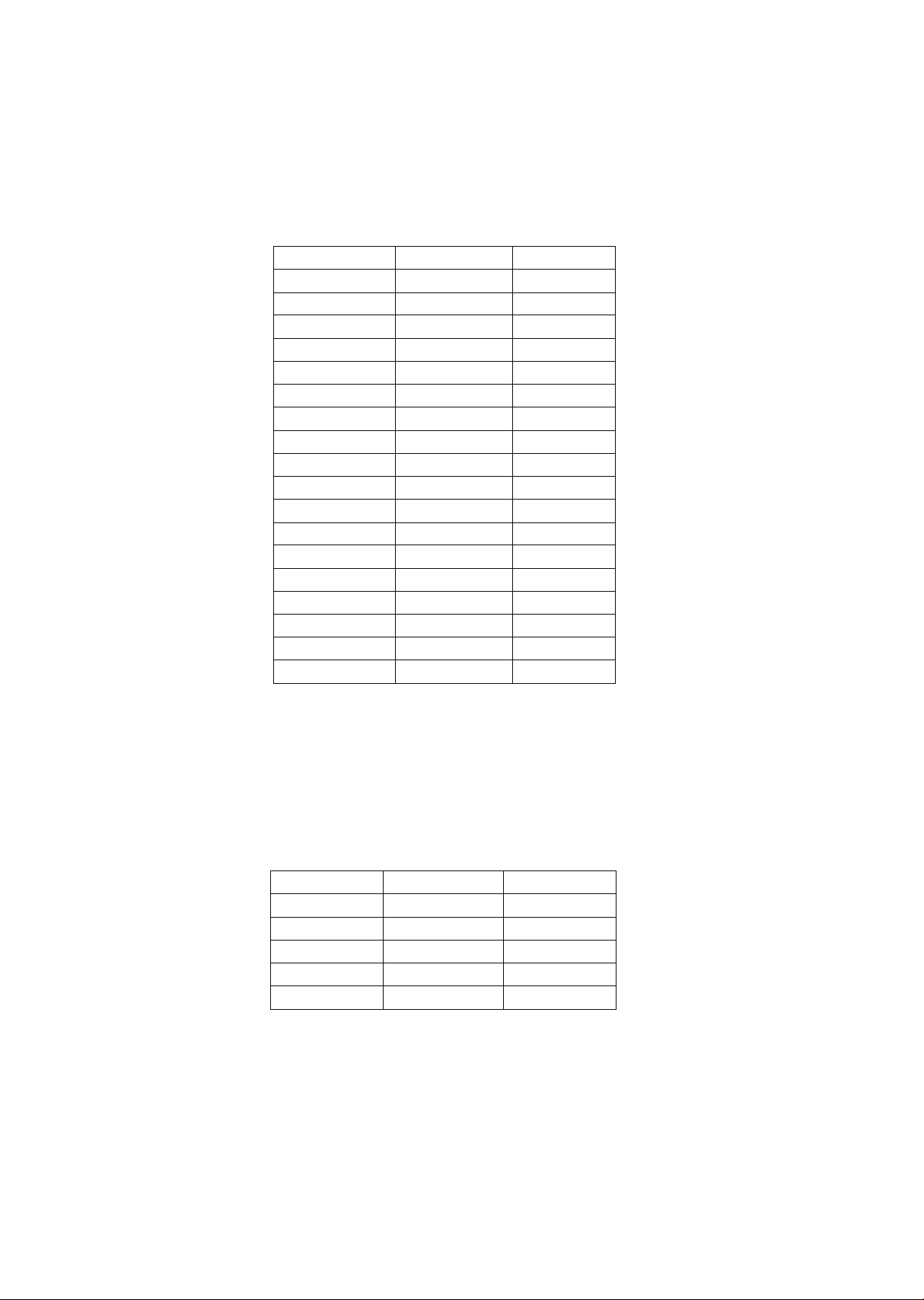
Plateau
The Plateau program provides a steady speed and varied grade
exercise with warm up and cool down periods.
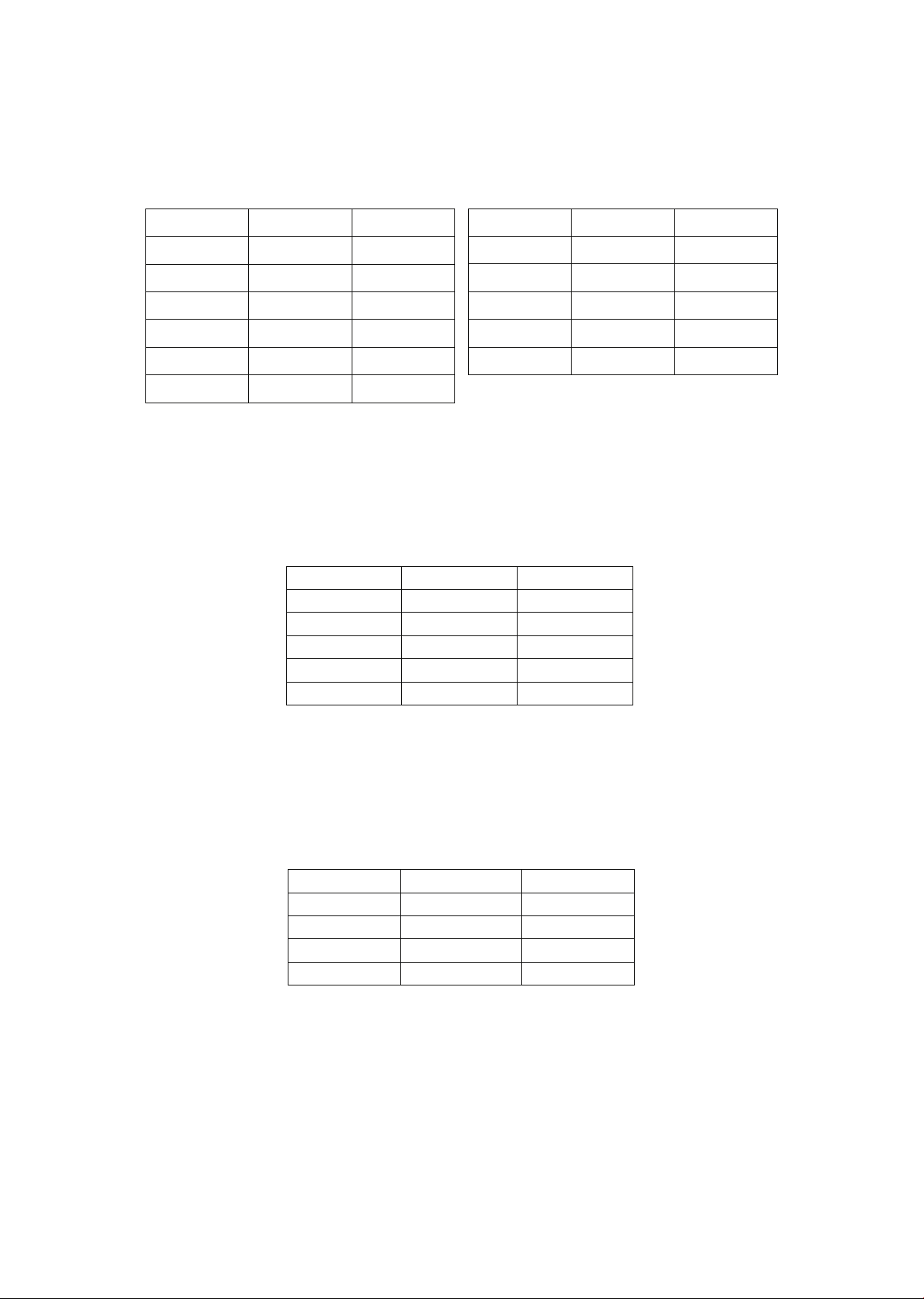
Interval
The Interval program takes you through high levels of intensity
followed by periods of low intensity. This program increases your
endurance by depleting your oxygen level followed by periods of
recovery to replenish oxygen. Your cardiovascular system gets
programmed to use oxygen more eciently this way.

24
Custom program
The custom program allows you to build and save a custom program.
You can build your own custom program by following the instructions
below. The custom program allows you to further personalize it by
adding your facility name.
• Designing and saving a new program as a custom program. The
message window will show a welcome message; if you had
previously saved a program the message will contain the name you
gave it. Then press the Conrm key to begin programming.
- When you press Confirm, the Message Window will show
“Name – XXXXXXX”, if there is no name saved. If the name
“CustomA” had been previously saved the Message Window will
show “Name – CustomA” and the C in Custom will be blinking. If
there is a name saved you can change it or you may press the Stop
key to keep the name and continue to the next step. If you want to
enter a name use the Plus and/or the Minus key to change the rst
letter then press Conrm to save the rst letter and continue to the
next letter. When you have finished entering the name press the
Stop key to save the name and continue to the next step.
- The Message window will ask you to enter an Age. You may enter an
Age, using the Plus and Minus keys, then press the Conrm key to
accept the new number and proceed on to the next screen.
- You are now asked to enter a Weight. You may adjust the Weight
number using the Plus and Minus keys and then press Conrm to
continue.
- Next is Time. You may adjust the Time and press Confirm to
continue.
- Now you are asked to enter the speed of each segment.

25
- Now the first column will be blinking and you are asked to adjust
the level of speed for the first segment of the workout. When you
finish adjusting the first segment, or if you don’t want to change,
then press Conrm to continue to the next segment.
- The next segment will show the same level as the previously
adjusted segment. Repeat the same process as the last segment
then press Conrm. Continue this process until all twenty four
segments have been set.
- Now you are asked to enter the grade of each segment. Repeat the
process same as above speed setting, until all twenty four segments
have been set.
- The Message Window will then tell you to press Confirm to save the
program. After saving the program the Message Window says
“PRESS START TO BEGIN OR CONFIRM TO MODIFY” then will give
you the option to start or modify the program. Pressing Stop will
exit to the start up screen.
- During the Custom program you will be able to scroll through the
data in the Message Window by pressing the Display key.
- Use the heart rate monitoring features and can switch to Heart Rate
Auto-Pilot mode (See HR auto pilot section for details of this
feature).

26
VO2 Test
The VO2 program is based on the YMCA protocol and is a sub-
maximal test that uses pre-determined, xed work levels that are
determined based on the heart rate readings measured as the test
progresses.
At the end of the test a VO2 score will be displayed. VO2 stands for
Volume of Oxygen uptake which is a measurement of how much
oxygen you need to perform a known amount of work. The YMCA
protocol employs two to four stages, lasting 3 minutes each, of
continuous exercise (see charts below). You will be prompted to
choose either, Male or Female at the beginning of the test. This
choice determines which protocol will be used during the test as
shown in the charts below. The only caveat is if you are a very
de-conditioned male you may need to choose option Female. If you
are a very conditioned female you may need to choose option Male.
VO2 test programming
• When the VO2 key is pressed the message window displays:
GERKIN. This is the first of 9 different tests available: Gerkin, WFI
(Wellness Fitness Initiative), Army, Navy, Air Force, Marines, PEB
(Physical Efficiency Battery), Coast Guard, and CTT (Chester T
readmill Test). The initial test is Gerkin; to select a different test
press the VO2 key again and the next test will be shown. Continue
to press the VO2 key until the test you want is shown in the
message window. To select your desired test, press Conrm.
• (Except CTT-performance)You are now prompted to enter your Age.
You may adjust the age using the Plus and Minus key then press
Conrm to continue.
• You are now prompted to enter your Weight. You may adjust the
weight using the Plus and Minus key then press enter to continue
• (Only for WFI)You are now prompted to enter your Height. You may
adjust the age using the Plus and Minus key then press Confirm to
continue.
• The Message Window will prompt you to enter your Gender. Use the
Plus and Minus keys to change and press the Conrm key to accept
and proceed on to the next screen.
• Now press Start to begin the test.

27
Before the Gerkin/WFI test:
• Make sure you are in good health; check with your physician before
performing any exercise if you are over the age of 35 or persons with
pre-existing health conditions.
• Make sure you have warmed up and stretched before taking the
test.
• Do not take in caffeine before the test.
• Hold the hand grips gently if you don’t wear your wireless chest
strap transmitter, do not tense up.
During the test
• The console must be receiving a steady heart rate for the test to
begin. You may use the hand pulse sensors or wear a heart rate
chest strap transmitter, although chest strap transmitter is
recommended.
• The test will start with a 3-minute warm-up at 3 MPH (4.8 km/hr)
before the actual test begins.
After the test
• Cool down for about one to three minutes.
• Take note of your score because the console will automatically
return to the start-up mode after a few minutes.

28
Gerkin
The Gerkin protocol, also known as the reman’s protocol, is a
sub-max Vo2 (volume of oxygen) test. The test will increase speed
and elevation alternately until you reach 85% of your Max heart
rate. The time it takes for you to reach 85% determines the test
score (VO2max) as shown in the chart below.
Stage
Time
Speed
Grade
VO2 Max
1 0 to 1:00 4.5mph 0% 31.15
2.1 1:00~1:15 4.5mph 2% 32.55
2.2 1:15~1:30 4.5mph 2% 33.6
2.3 1:30~1:45 4.5mph 2% 34.65
2.4 1:45~2:00 4.5mph 2% 35.35
3.1 2:00~2:15 5.0mph 2% 37.45
3.2 2:15~2:30 5.0mph 2% 39.55
3.3 2:30~2:45 5.0mph 2% 41.3
3.4 2:45~3:00 5.0mph 2% 43.4
4.1
3:00~3:15 5.0mph
4%
44.1
4.2 3:15~3:30 5.0mph 4% 45.15
4.3 3:30~3:45 5.0mph 4% 46.2
4.4 3:45~4:00 5.0mph 4% 46.5
5.1 4:00~4:15 5.5mph 4% 48.6
5.2
4:15~4:30 5.5mph
4%
50
5.3 4:30~4:45 5.5mph 4% 51.4
5.4 4:45~5:00 5.5mph 4% 52.8
6.1 5:00~5:15 5.5mph 6% 53.9
6.2 5:15~5:30 5.5mph 6% 54.9
6.3 5:30~5:45 5.5mph 6% 56
6.4 5:45~6:00 5.5mph 6% 57
7.1
6:00~6:15 6.0mph
6%
57.7
7.2 6:15~6:30 6.0mph 6% 58.8
7.3 6:30~6:45 6.0mph 6% 60.2
7.4 6:45~7:00 6.0mph 6% 61.2
8.1 7:00~7:15 6.0mph 8% 62.3
8.2 7:15~7:30 6.0mph 8% 63.3
8.3 7:30~7:45 6.0mph 8% 64
8.4 7:45~8:00 6.0mph 8% 65
9.1 8:00~8:15 6.5mph 8% 66.5
9.2 8:15~8:30 6.5mph 8% 68.2
9.3 8:30~8:45 6.5mph 8% 69
9.4 8:45~9:00 6.5mph 8% 70.7
10.1
9:00~9:15 6.5mph
10%
72.1
10.2 9:15~9:30 6.5mph 10% 73.1
10.3 9:30~9:45 6.5mph 10% 73.8
10.4 9:45~10:00 6.5mph 10% 74.9
11.1 10:00~10:15 7.0mph 10% 76.3
11.2
10:15~10:30
7.0mph
10%
77.7
11.3 10:30~10:45 7.0mph 10% 79.1
11.4 10:45~11:00 7.0mph 10% 80
29
WFI
The WFI test is a modified Gerkin protocol. The actual test is the
same as the Gerkin chart above, but the score is calculated
dierently.
Program Speed and Incline Chart
Army
A timed 2 mile (3.2 kilometer) run. You control the speed manually.
Maximum time allowed to pass the test.
• For more detailed information, visit: http://bit.ly/SF-Army
TIME
SPEED (MPH) % Grade
0:00-1:00 3.0 0
1:01 - 2:00 3.0 0
2:01 - 3:00 3.0 0
3:01 - 4:00 4.5 0
4:01 - 5:00 4.5 2
5:01 - 6:00 5.0 2
6:01 - 7:00 5.0 4
7:01 - 8:00 5.5 4
8:01 - 9:00 5.5 6
9:01 - 10:00 6.0 6
10:01 - 11:00 6.0 8
11:01 - 12:00 6.5 8
12:01 - 13:00 6.5 10
13:01 - 14:00 7.0 10
14:01 - 15:00 7.0 12
15:01 - 16:00 7.5 12
16:01 - 17:00 7.5 14
17:01 - 18:00 8.0 14
Age
Male
Female
17-21 16:36 19:42
22-26 17:30 20:36
27-31 17 :54 21:42
32-36 18:48 23:06
37-41 19:30 24:06
30
Navy
A timed 1.5 mile (2.4 kilometer) run. You control the speed manually.
Maximum time allowed to pass the test.
• For more detailed information, visit: http://bit.ly/SF-Navy
Air force
A timed 1.5 mile (2.4 kilometer) run. You control the speed manually.
Maximum time allowed to pass the test.
• For more detailed information, visit: http://bit.ly/SF-AirForce
Marines
A timed 3 mile (4.8 kilometer) run. You control the speed manually.
Maximum time allowed to pass the test.
• For more detailed information, visit: http://bit.ly/SF-Marines
PEB
A timed 1.5 mile (2.4 kilometer) run. You control the speed manually.
Maximum time allowed to pass the test.
• For more detailed information, visit: https://www.fletc.gov
/peb-scores-age-and-gender
Age
Male
Female
<30 13:36 16:22
30-30 14:00 16:57
40-49 14:52 18:14
50-59 16:22 19:43
60+ 18:14 22:28
Age
Male
Female
19 12:30 15:00
20-24 13:30 15:30
25-29 14:00 16:08
30-34 14:30 16:45
35-39 15:00 17:00
40-44 15:30 17:15
Age
Male
Female
45-49 16:08 17:23
50-54 16:45 17:30
55-59 17:09 18:34
60-64 18:52 19:43
65+ 20:35 20:52
Age
Male
Female
17-26 28:00 31:00
27-39 29:00 32:00
40-45 30:00 33:00
46+ 33:00 36:00

31
Coast guard
A timed 1.5 mile (2.4 kilometer) run. You control the speed manually.
Maximum time allowed to pass the test.
CTT
This test has two modes: CTT Performance and CTT Prediction
(of Aerobic Capacity)
CTT Performance is a 12 minute graded, treadmill walk test with a
fixed speed of 6.2km/hr (3.8 MPH) designed to assess whether or
not the subject can achieve the minimum recommended standard
for aerobic capacity, namely 42mlsO2/kg/min.
Procedures:
1. Check there are no medical contraindications to performing
exhaustive exercise
2. Subject walks at 6.2km/hr (3.8 MPH) at 0% for 2 mins
3. Every 2 mins increase gradient by 3%
4. Test is completed after 12 mins
5. Test should be stopped if subject is showing overt signs of distress
and exhaustion or RPE=18+
CTT Prediction is a submaximal test designed to predict aerobic
capacity
1. Same walk protocol as CTT Performance but wearing HR monitor
2. Test is stopped when the subject reaches 80%HRMax or RPE=14
3. A VO2 score is given at the end of the test
Male
20-29 Yrs. Old
30-39 Yrs. Old
40-49 Yrs. Old
50-59 Yrs. Old
60+ Yrs. Old
20-29 Yrs. Old 30-39 Yrs. Old 40-49 Yrs. Old 50-59 Yrs. Old 60+ Yrs. Old
Superior <9:17 <9:33 <9:51 <10:37 <11:26
Excellent 9:18-10:09 9:34-10:46 9:52-11:15
11:16-12:24
10:28-12:08
12:09-13:35
11:27-13:23
Good 10:10-11:29 10:47-11:54 13 :24-15:04
Fair 11:30-12:38 11:55-12:28
12:25 -13:50 13:36 -15:06 15:05 -16:46
Poor 12:39 -14:00 12:59-14:34 13 :51-15:24 1 5:07-16:28 16:47-19 :10
Very Poor >14:00 >14 :34 >15 :24 >16 :28 >19 :10
Failure
>12:51
>1 3:36
>1
4
:
29
>1
5
:
26
>1
6
:
40
Female
Superior
<
10
:
28
<
11
:
00
<
11
:
33
<
12
:
53
<
14
:
05
Excellent 10:29 -11:59 11:01 - 12:24 11:34-1 3:23 12: 54-1 4:34 14:06-16 :33
Good 11:59 -13:34 12:25-14:08 13:24-14:53 1 4:35-16:35 16:34-18 :27
Fair 13:25-14:50 1 4:09-15:43 1 4:54-1 6:31 1 6:36-18:18 18:28-20:16
Poor 14:51 - 16:46 15:44 -17:38 16:32 -18:37 18:19 -20:44 20:17-22:52
Very Poor
>1
6
:
46
>1
7
:
38
>1
8
:
37
>
20
:
44
>
20
:
52
Failure >15 :26 >15 :57 >1 6:58 >17 :55 >18 :44

32
What the score means
VO2max Chart for males and very fit females
VO2max Chart for females and de-conditioned males
METs program
METs stands for metabolic equivalent, which is one way that
exercise physiologists estimate how many calories are burned
during physical activity.
1 MET is essentially the amount of energy produced relative to body
mass whilst at rest. As you sit here now reading you are expending
1 MET of energy.
18-25
26-35
36-45
46-55
65+
years
old
years
old
years
old
years
old
years
old
years
old
excellent
>60 >56 >51 >45 >41 >37
good 43-51
52-60
49-56
39-45
36-41
33-37
above
average
47-51
43-48
39-42
35-38
32-35
29-32
average
42-46
40-42
35-38
32-35
30-31
26-28
below
average
37-41
35-39
31-34
29-31
26-29
22-25
poor 30-
34
30-36
26-30
25-28
22-25
20-21
very
poor <30 <30
<26 <25 <22 <20
56-65
18-25 26-35 36-45 46-55 65+
years
old
years
old
years
old
years
old
years
old
years
old
excellent
56
52
45
40
37
32
good 47-56
45-52
38-45
34-40
32-37
28-32
above
average
42-46
39-44
34-37
31-33
28-31
25-27
average 38-41
35-38
31-33
28-30
25-27
22-24
below
average
33-37
31-34
27-30
25-27
22-24
19-22
poor
28-32
26-30
22-26
20-24
18-21
17-18
very
poor
<28
<26
<22
<20
<18
<17
56-65

33
Using 1 MET as the reference value, light activities burn up to 3 times as
many calories as rest, moderate activities burn 3-6 times as many and
vigorous exercise turns over more than 6 times as much energy as rest.
METs programming
• Press the METs key and then press Confirm.
• The Message Window will prompt you to enter your age. Use the Plus
and Minus keys to change and press the Conrm key to continue.
• You are now prompted to enter your weight. You may adjust the age
using the Plus and Minus key then press Conrm key to continue.
• You are now prompted to enter your workout time. You may adjust the
time using the Plus and Minus key then press Conrm to continue.
• You are now prompted to enter your target METs. You may adjust the
target METs using the Plus and Minus keys then press Confirm to
continue.
• Now press Start to begin the program.

34
Metabolic rate activity chart
MET
<3
0.9
1.0
1.5
2.3
2.9
3 to 6
3.0
3.3
3.5
3.6
4.0
5.5
5.8
> 6
7.0
8.0
8.0
8.8
9.8
10.0
10.5
11.0
11.2
Physical activity
Light intensity activities
Moderate intensity activities
Vigorous intensity activities
sleeping
watching television
writing, desk wirk, typing
walking, 1.7mph (2.7 km/h), level ground, strolling, very slow
walking 2.5 mph (4 km/h)
bicycling, stationary, 50 watts, very light eort
walking 3.0 mph (4.8 km/h)
calisthenics, home exercise, light or moderate eort, general
walking 3.4 mph (5.5 km/h)
bicycling, <10 mph (16 km/h), leisure, to work or for pleasure
bicycling, stationary, 100 watts, light eort
sexual activity
jogging, general
calisthenics (e.g. pushups, situps, pullups, jumping jacks),
heavy, Vigorous effort
running jogging, in place
jogging, 5.6 mph (9.0 km/h)
rope jumping (66/min)
rope jumping (70/min)
rope jumping (84/min)
rope jumping (100/min)
jogging, 6.8 mph (11.0 km/h)

35
Heart rate program
The old motto; “no pain, no gain” is a myth that has been
overpowered by the benets of exercising comfortably. A great deal
of this success has been promoted by the use of heart rate monitors.
With the proper use of a heart rate monitor, many people find that
their usual choice of exercise intensity was either too high or too low
and exercise is much more enjoyable by maintaining their heart rate
in the desired benet range.
To determine the benet range in which you wish to train, you must
rst determine your maximum heart rate. This can be accomplished
by using the following formula: 220 minus your age. This will give you
the maximum Heart rate (MHR) for someone of your age. To
determine the eective heart rate range for specic goals you simply
calculate a percentage of your MHR. Your Heart rate training zone is
50% to 90% of your maximum heart rate. 60% of your MHR is the
recommended for burning fat while 80% is recommended for
strengthening the cardio vascular system. This 60% to 80% is the
zone to stay in for maximum benet.
For someone who is 40 years old their target heart rate zone is
calculated:
220 – 40 = 180 (maximum heart rate)
180 x .6 = 108 beats per minute (60% of maximum)
180 X .8 = 144 beats per minute (80% of maximum)
So for a 40 year old the training zone would be 108 to 144 beats per
minute.
90

36
If you enter your age during programming the console will perform
this calculation automatically. Entering your age is used for the heart
rate programs. After calculating your MHR you can decide upon which
goal you would like to pursue.
The two most popular reasons for, or goals, of exercise are
cardiovascular fitness (training for the heart and lungs) and weight
control. The black columns on the chart above represent the MHR for
a person whose age is listed at the bottom of each column. The
training heart rate, for either cardiovascular tness or weight loss, is
represented by two dierent lines that cut diagonally through the
chart. A denition of the lines’ goal is in the bottom left-hand corner
of the chart. If your goal is cardiovascular tness or if it is weight loss,
it can be achieved by training at 80% or 60%, respectively, of your
MHR on a schedule approved by your physician. Consult your
physician before participating in any exercise program.
With all heart rate programs you may use the heart rate monitor
feature without using the Heart Rate program. This function can be
used during manual mode or during any other dierent programs. The
heart rate program automatically controls resistance at the pedals.
Rate of perceived exertion
Heart rate is important but listening to your body also has a lot of
advantages. There are more variables involved in how hard you
should workout than just heart rate. Your stress level, physical health,
emotional health, temperature, humidity, the time of day, the last
time you ate and what you ate, all contribute to the intensity at which
you should workout. If you listen to your body, it will tell you all of
these things.

37
The rate of perceived exertion (RPE), also known as the Borg scale,
was developed by Swedish physiologist G.A.V. Borg. This scale rates
exercise intensity from 6 to 20 depending upon how you feel or the
perception of your eort. The scale is as follows:
You can get an approximate heart rate level for each rating by simply
adding a zero to each rating. For example a rating of 12 will result in
an approximate heart rate of 120 beats per minute. Your RPE will vary
depending upon the factors discussed earlier. That is the major
benet of this type of training. If your body is strong and rested, you
will feel strong and your pace will feel easier. When your body is in
this condition, you are able to train harder and the RPE will support
this. If you are feeling tired and sluggish, it is because your body
needs a break. In this condition, your pace will feel harder. Again, this
will show up in your RPE and you will train at the proper level for that
day.
Rating perception of eort
6 Minimal
7 Very, very light
8 Very, very light +
9 Very light
10 Very light +
11 Fairly light
12 Comfortable
13 Somewhat hard
14 Somewhat hard +
15 Hard
16 Hard +
17 Very hard
18 Very hard +
19 Very, very hard
20 Maximal

38
Heart rate program programing
To start the HR program follow the instructions below and follow the
directions in the message window.
• Press the HR key to select the HR program (Target HR 65 Percent /
Target HR 80 Percent / HR interval) and then press the Confirm key to
enter.
• The Message Window will ask you to enter your Age. You may enter
your Age, using the Plus and Minus key, then press the Conrm key to
accept the new number and proceed on to the next screen.
• You are now asked to enter your Weight. You may adjust the Weight
number using the Plus and Minus keys, then press Conrm to continue.
• Next is Time. You may adjust the Time and press enter to continue.
• Now you are asked to adjust the target HR. This is the target HR in
Target HR 65 Percent program or in Target HR 80 Percent program or
Work and Rest heart rate level in HR Interval program you will experi-
ence during the program. Adjust the target number and then press
Conrm.
• Now you are finished editing the settings and can begin your workout
by pressing the Start key. You can also go back and modify your set-
tings by pressing the Confirm key. NOTE: At any time during the editing
of data you can press the Stop key to go back one level, or screen.
• If you want to increase or decrease the workload at any time during the
program press the Plus or Minus keys. This will allow you to change
your target heart rate at any time during the program.
• During the HR program you will be able to scroll through the data in
the Message Window by pressing the Display key.
When the program ends you may press Start to begin the same program
again or Stop to exit the program.

39
Heart rate auto pilot mode
The HR auto pilot mode only works in Fitness programs (Manual / 5K
/ Hill / Plateau / Interval / Custom). When you are exercising in a fitness
program and decide to just maintain the HR level you are at currently
you can just press auto pilot and the console will automatically switch
to HR control and will maintain your current HR. To start the HR auto
pilot mode follow the instructions below and the directions in the Mes-
sage Window.
• Press the HR auto pilot key during the fitness programs. It is necessary
to wear HR strap to enter this mode. If a HR is not detected the
message window shows NO HEART RATE.
• At the end of the HR auto pilot program a workout summary will be
displayed in the Message Window.

35
40
Note: The chest strap transmitter is not a standard part, but is a
separate purchase. Most transmitters that operate at Bluetooth or
ANT+ will also work.
How to wear your wireless chest strap transmitter?
• Attach the transmitter to the elastic strap using the locking parts.
• Adjust the strap as tightly as possible as long as the strap is not too
tight to remain comfortable.
• Position the transmitter with the logo centered in the middle of your
body facing away from your chest (some people must position the
transmitter slightly left of center). Attach the final end of the elastic
strap by inserting the round end and, using the locking parts, secure
the transmitter and strap around your chest.
• Position the transmitter immediately below the pectoral muscles.
Using
a heart rate
transmitter

41
• Sweat is the best conductor to measure very minute heart beat
electrical signals. However, plain water can also be used to pre-wet
the electrodes (2 black square areas on the reverse side of the belt
and either side of transmitter). It’s also recommended that you wear
the transmitter strap a few minutes before your work out. Some users,
because of body chemistry, have a more dicult time in achieving a
strong, steady signal at the beginning. After “warming up”, this problem
lessens. As noted, wearing clothing over the transmitter/strap doesn’t
aect performance.
• Your workout must be within range - distance between transmitter /
receiver – to achieve a strong steady signal. The length of range may
vary somewhat but generally stay close enough to the console to
maintain good, strong, reliable readings. Wearing the transmitter
immediately against bare skin assures you of proper operation. If you
wish, you may wear the transmitter over a shirt. To do so, moisten the
areas of the shirt that the electrodes will rest upon.
Note: The transmitter is automatically activated when it detects
activity from the user’s heart. Additionally, it automatically
deactivates when it does not receive any activity. Although the
transmitter is water resistant, moisture can have the eect of creating
false signals, so you should take precautions to completely dry the
transmitter after use to prolong battery life. (estimated transmitter
battery life is 2500 hours). If your chest strap has a replaceable
battery the replacement battery is CR2032.

42
Erratic operation
Caution! Do not use this product for heart rate control unless a
steady, solid actual heart rate value is being displayed. High, wild,
random numbers being displayed indicate a problem.
Areas to look at for interference, which may cause erratic heart rate
• Microwave ovens, TVs, small appliances, etc.
• Fluorescent lights.
• Some household security systems.
• Perimeter fence for a pet.
• Some people have problems with the transmitter picking up a signal
from their skin. If you have problems try wearing the transmitter upside
down. Normally the transmitter will be oriented so the logo is right side
up.
• The antenna that picks up your heart rate is very sensitive. If there is an
outside noise source, turning the whole machine 90 degrees may
de-tune the interference.
• If there is another person wearing a chest strap within 1 meter, it will
interfere.
• If you continue to experience problems contact your dealer.

43
• Belt and deck
Your treadmill uses a very high-ecient low-friction deck and belt.
Performance is maximized when the bed is kept as clean as
possible. Use a soft, damp cloth or paper towel to wipe the edge of
the belt and the area between the belt edge and frame. Also reach
as far as practical directly under the belt edge. This should be done
once a month to extend belt and deck life. Use water only no
cleaners or abrasives. A mild soap and water solution along with a
nylon scrub brush will clean the top of the textured belt.
Allow the belt to dry before using.
The low maintenance (routine monthly cleaning), dual-sided hard
wax deck is designed to withstand up to 20,000 miles (32,000
kilometers) on each side. If the original side of the deck shows
significant wear, it needs to be flipped. Contact your service
technician for assistance. Do not apply any type of lubricant or wax
to the surface.
• Belt dust
This occurs during normal break-in or until the belt stabilizes.
Wiping excess off with a damp cloth will minimize buildup.
• General Cleaning
Dirt, dust, and pet hair can block air inlets and accumulate on the
running belt. On a monthly basis: vacuum underneath your treadmill
to prevent buildup. Once a year, you should remove the black motor
hood and vacuum out dirt that may accumulate. UNPLUG POWER
CORD BEFORE THIS TASK.
Maintenance
44
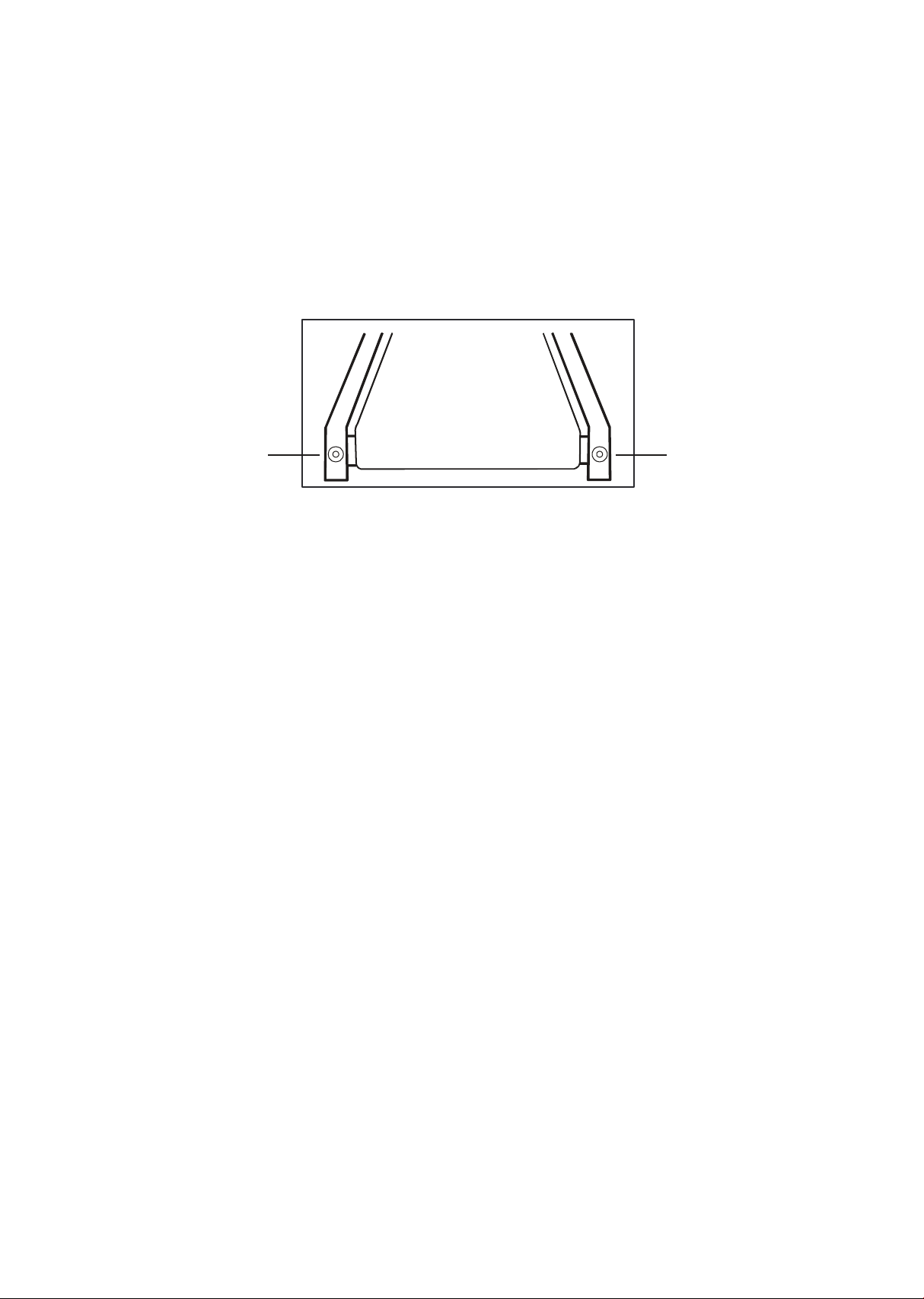
Belt adjustments
• Tread-belt tension adjustment
Belt tension is not critical for most users. It is very important though
for joggers and runners in order to provide a smooth, steady running
surface. Adjustment must be made from the rear roller with the
8mm Allen wrench provided in the parts package. The adjustment
bolts are located at the end of the step rails as shown in the
diagram below.
Note: Adjustment is through small hole in the end cap.
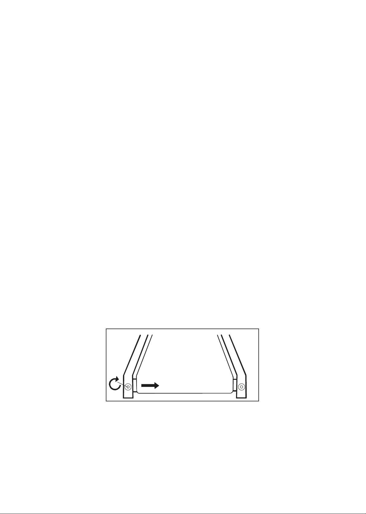
Tighten the rear roller only enough to prevent slippage at the front roller.
Turn the treadbelt tension adjusting bolts 1/4 turn each and inspect for
proper tension by walking on the belt and making sure it is not slipping
or hesitating with each step. When an adjustment is made to the belt
tension, you must be sure to turn the bolts on both sides evenly or the
belt could start tracking to one side instead of running in the middle of
the deck.
Do not over tighten
Over tightening will cause belt damage and premature bearing failure. If
you tighten the belt a lot and it still slips, the problem could actually be
the drive belt—located under the motor cover—that connects the motor
to the front roller. If that belt is loose it feels similar to the walking belt
being loose. Tightening the motor belt should be done by a trained
service person.
Tracking /
Tension
Adjustment
Tracking /
Tension
Adjustment
45
Treadbelt tracking adjustment
The treadmill is designed so that the treadbelt remains reasonably
centered while in use. It is normal for some belts to drift near one
side while in use, depending on a user’s gait and if they favor one
leg. But if during use the belt continues to move toward one side,
adjustments are necessary.
Setting treadbelt tracking
An 8mm Allen wrench is provided for this adjustment. Make tracking
adjustments on the left side bolt. Set the belt speed to 3 mph. Be
aware that a small adjustment can make a dramatic difference
which may not be apparent right away. If the belt is too close to the
left side, then turn the bolt only a 1/4 turn to the right (clockwise)
and wait a few minutes for the belt to adjust itself. Continue to
make 1/4 turns until the belt stabilizes in the center of the running
deck.
If the belt is too close to the right side, turn the bolt counter-
clockwise. The belt may require periodic tracking adjustment
depending on use and walking/ running characteristics. Some users
may affect tracking differently. Expect to make adjustments as
required to center the treadbelt. Adjustments will become less of a
maintenance concern as the belt is used. Proper belt tracking is an
owner responsibility common with all treadmills.
Remember, a small adjustment can make a dramatic difference!

46
Troubleshooting
Before contacting your dealer for aid, please review the following
information. It may save you both time and expense.
Problem Cause
1. Tether cord not in position.
2.Circuit breaker on front grill tripped. Push circuit
breaker in until it locks.
3.Plug is disconnected. Make sure the plug is rmly
pushed into115 VAC wall outlet.
4.Breaker panel circuit breaker may be tripped.
Display does not light
The user may be walking while favoring or putting
more weight on either the left or right foot. If this
walking pattern is natural, track the belt slightly
o-center to the side opposite from the belt
movement. See Maintenance section on Tread- belt
Tension. Adjust as necessary.
This indicates motor should be receiving power to
operate. Do not use an extension cord. If an extension
cord is required, it should be as short as possible and
heavy duty, 16-gauge minimum, low voltage. Contact
an electrician or your dealer. A minimum of 110-volt AC
current is required.
High belt/deck friction. See Maintenance section on
cleaning the deck. If cleaning doesn’t prevent this from
reoccurring, check to see if there is signicant wear of
the deck. If so, the deck may need to be flipped if it is
on its original side.
High belt/deck friction. See Maintenance. If cleaning
doesn’t prevent this from reoccurring, check the amp
draw of the motor. If this is high and there are signs of
significant wear of the deck, it may need to be flipped
on its original side.
Treadmill may not be grounded. Static electricity is
crashing the computer. Refer to Grounding
Instructions.
Treadbelt does not stay
centered Treadmill belt
hesitates when walked/
run on
Treadmill will only achieve
approximately 7 mph but
shows higher speed on
display
Treadbelt stops quickly/
suddenly when tether cord is
pulled
Treadmill trip on board
20-amp circuit
Computer shuts o when
console is touched
(on a cold day)
while walking/running
Motor is not responsive
after pressing start
Reset power. If still no good contact service.
Circuit breaker trips, but not
the treadmill circuit breaker
Need to replace the breaker with a “High In-rush
current” type breaker

47
General maintenance
Task
How To
Daily
Weekly
Monthly
Semi-Annually
Annually
Wipe down unit Damp cloth
w/ water
Clean under belt Towel or
vacuum
Check belt
tension/tracking
Feel/visual
Clean under
motor cover
Vacuum
carefully
Check hardware Wrench
Inspect for deck
wear
Visual
Inspect drive
belt
Visual

48
Maintenance mode in console software
The console has built in maintenance/diagnostic software. The
software will allow you to change the console settings from English
to Metric and turn o the beeping of the speaker when a key is
pressed for example. To enter the Maintenance mode press and
hold down the Start, Stop and Confirm key. Keep holding the keys
down for about 2 seconds and the Message Window will display
“Maintenance mode”. Press the Conrm key to access the menu
below:
• Key test
- Will allow you to test all the keys to make sure they are function
ing. Press all the keys one at a time.
• Display test
- Tests all the display functions by lighting each LED light
sequentially.
• Functions (press Confirm key to access menu)
- Units
Set to English (imperial units) or metric display readings. The default
is imperial, which means data such as body weight and height will
be in pounds and inches.
- Pause mode
Turn on allow 5 minutes of pause, turn o to have the console
pause indenitely.
- Odometer reset
Resets the odometer to zero (Time and distance)
- Beep sound
Turn on or o the speaker to silence beeping sound.
- LED brightness
Adjust the LED brightness.
- Modle
Select the kind of device.
• Service
- Brake test
- CSAFE test
Test the CSAFE functions.
• ANT ID
- Adjust the ANT ID.
• Update code
- Switch bootloader on/o. The default is o.
• Exit
- Press Conrm key to leave maintenance mode and restart.
49
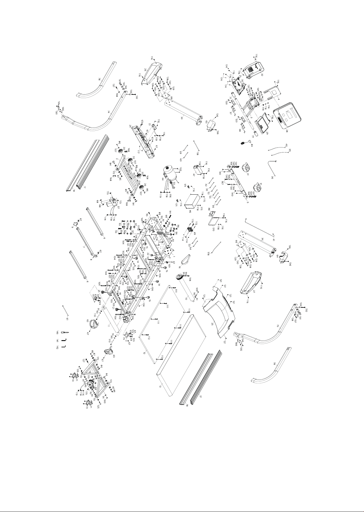
Exploded view drawing

50
4.0 T parts list
Item Description Qty
1
2
3
4
5
6
7
8
9
10
11
12
13
14
15
16
17
18
19
20
21
22
24
25
26
27
28
29
30
31
32
33
34
Main Frame
Incline Bracket
Console Support
Console Support
Handle Bar
Running Deck Stabilizer Assembly(A)
Running Deck Stabilizer Assembly(B)
Belt Guide(R)
Belt Guide(L)
Front Roller W/Pulley
Rear Roller
Running Deck
Running Belt
Cushion A
Cushion B
Drive Belt
Aluminum Foot Rail(122×39×1390L)
Aluminum Foot Rail(125×29×1390L)
Rear Incline Bracket
Transportation Wheel
Foot Pad
Incline Rubber Foot
Front Motor Cover
Motor Top Cover
Motor Base Cap (L)
Motor Base Cap (R)
Console Assembly
Switch Top Cover
Switch Bottom Cover
Drink Bottle Holder
Console Cover
Left Upright
Right Upright
1
1
1
1
1
2
1
1
1
1
1
1
1
2
4
1
2
2
1
4
2
2
1
1
1
1
1
1
1
2
1
1
1

51
Item Description Qty
35
36
37
38
39
40
41
42
43
44
46
47
48
49
50
51
52
53
54
55
56
57
58
59
60
61
62
63
64
65
66
67
68
200m/m_Ground Wire
550m/m_Computer Cable (Upper/Lower)
900m/m_Handpulse W/Cable Assembly(XHP-4)
900m/m_Handpulse W/Cable Assembly(XHP-3)
600m/m_Computer Cable
600m/m_Computer Cable (Upper)
Computer Cable(Lower)
300m/m_Connecting Wire
Incline Motor
AC Motor
Inverter
Filter
Inverter Board
Fan
Ø35 × 21 × 13L_Ferrite Core
AC Electronic Module
450m/m_Connecting Wire (White)
Motor Fan Connecting Cable(White)
Motor Fan Connecting Cable (Black)
250m/m_Connecting Wire(White)
250m/m_Connecting Wire(Black)
Incline Motor
600m/m_Connecting Cable
300m/m_Ground Wire
450m/m_Connecting Wire (Black)
Power Cord
Rear Adjustment Base (L)
Rear Adjustment Base (R)
Handgrip Cap (R)
Handgrip Cap (L)
Upright Fixing Plate
5 × 20m/m_Tapping Screw
Ø10 × Ø25 × 2.5T_Nylon Washer
1
1
1
1
1
1
1
1
1
1
1
1
1
1
1
1
1
1
1
2
2
1
1
1
1
1
1
1
1
1
2
18
4

54
Item Description Qty
69
70
71
72
73
74
75
77
78
83
84
85
86
87
88
89
90
91
92
93
94
95
96
97
98
99
100
101
102
103
104
105
106
Ø25 × Ø25 × 15T_Rubber Foot Pad
Ø19 × Ø14 × Ø10 × (5+4)_Bushing
Foot Pad Bracket
Foot Pad
Adjustment Rail Pad
Handle Bar(L)
Handle Bar(R)
Ø38 × 3T × 90m/m_Handgrip Foam
Ø30 × 70 × 3T × 1160m/m_Handgrip Foam
Square Safety Key
Ø18 × Ø19 × 41L_Carriage Bolt
M8 × 12m/m_Hex Head Bolt
3/8" × 25m/m_Hex Head Bolt
Ø8.5 × Ø26 × 2.0T_Flat Washer
M10 × 65m/m_Hex Head Bolt
M10 × 50m/m_Hex Head Bolt
Ø10 × 1.5T_Split Washer
Ø3/8" × Ø19 × 1.5T_Flat Washer
M10 × P1.5 × 8T_Nylon Nut
3/8" × UNC16 × 1-1/2"_Socket Head Cap Bolt
3/8" × 2-1/2"_Hex Head Bolt
3/8" × UCN16 × 2"_Socket Head Cap Bolt
Ø10 × Ø14 × 14L_Bushing
Ø13 × Ø35 × 5T_Nylon Washer
Ø3/8" × 35 × 2.0T_Flat Washer
Ø10 × 2.0T_Split Washer
3/8" × 7T_Nylon Nut
M8 × 1.25 × 40m/m_Socket Head Cap Bolt
Ø8 × 1.5T_Split Washer
Ø5/16" × 16 × 1.0T_Flat Washer
M8 × 1.25 × 90m/m_Socket Head Cap Bolt
M8 × 55m/m_Hex Head Bolt
M8 × 1.25 × 6.5T_Square Nut
4
4
2
2
2
1
1
2
2
1
4
4
4
4
1
1
6
12
4
4
1
1
5
9
5
5
4
6
18
22
8
8
16

55
Item Description Qty
107
108
109
110
111
112
113
114
115
116
117
118
119
120
121
123
125
126
127
128
129
130
131
132
133
134
135
136
137
138
140
141
142
Ø3/8" × Ø25 × 2.0T_Flat Washer
M10 × 40m/m_Socket Head Cap Bolt
M10 × 80m/m_Socket Head Cap Bolt
M10 × 100m/m_Socket Head Cap Bolt
M8 × P1.25 × 55L_Flat Head Countersink Bolt
M8 × 35m/m_Flat Head Countersink Bolt
M3 × 50m/m_Phillips Head Screw
M3 × 5T_Nylon Nut
M5 × 20m/m_Phillips Head Screw
M5 × 12m/m_Phillips Head Screw
M5 × 5T_Nylon Nut
Ø5 × 1.5T_Split Washer
M5_Star Washer
3 × 25m/m_Tapping Screw
5 × 12m/m_Sheet Metal Screw
5 × 25m/m_Tapping Screw
M10 × P1.5 × 50L_Button Head Socket Bolt
3/8" × UNC16 × 1-1/2"_Socket Head Cap Bolt
3/8" × UNC16 × 2-1/2"_Socket Head Cap Bolt (Alloy Steel)
3/8" × 3"_Button Head Socket Bolt
Ø3/8" × 35 × 2.0T_Flat Washer
Ø10 × 2.0T_Split Washer
M8 × 45m/m_Button Head Socket Bolt
M8 × 80L_Button Head Socket Bolt
Ø10 × Ø23 × 1.5T_Curved Washer
M5 × 40m/m_Phillips Head Screw
M8 × 20m/m_Button Head Socket Bolt
M5 × 12m/m_Phillips Head Screw
M8 × P1.25 × 35L_Button Head Socket Bolt
Ø5/16" × Ø23 × 1.5T_Flat Washer
M5 × 10m/m_Tapping Screw
L Allen Wrench
6mm Allen Wrench
4
1
1
2
6
2
4
4
2
31
2
11
5
4
6
4
2
1
1
10
10
28
12
2
2
2
4
4
2
2
4
1
1

56
Item Description Qty
143
166
167
168
169
170
171
172
173
174
178
5/16" × unc18 × 1-1/4"_hex head bolt
3/8" × unc16 × 1-3/4"_socket head cap bolt
Combination m6 allen wrench & phillips head screw driver
Console chin cover
Hgp wire grommet
Ø5/16" × 16 × 1.0t_flat washer
Seat back cover
M6 × 6t_nyloc nut
14/15m/m_wrench
Ø6.6 × ø12 × 1.5t_flat washer
Fixing plate
1
2
1
1
1
3
1
1
1
4
1

57
Product warranty
Dyaco Commercial & Medical North America LLC (hereinafter
“Dyaco”), the manufacturer of the Philips Commercial Series Physical
Therapy Products (hereinafter “Products”) warrants all of the
Products and their components listed below for the periods of time
set out on this page below from the date of sale, as determined by
sale receipt, or in the absence of a sales receipt, ocial warranty
period + additional 6 months from the original factory shipping date.
During the applicable warranty periods, Dyaco’s responsibilities
under these warranties include providing, at no charge, new or
remanufactured parts, as determined by Dyaco at its sole and
absolute discretion, and covering the cost of labor deemed necessary
by Dyaco, at its sole and absolute discretion, to remedy faults giving
rise to applicable warranty claims. The warranty periods set out
below are subject to the performance of proper care and
maintenance, as set out in this user manual, by the original purchaser
of the equipment. Warranties are not transferable.
* Wear items are rubber hand grips, pedals, console overlay and
drive belt
Normal responsibilities of the facility
The facility is responsible for the items listed below
• The warranty registration must be completed online to validate the
manufacturer’s limited warranty.
• Proper use of the fitness equipment in accordance with the
instructions provided in this manual.
• Proper installation in accordance with instructions provided with
the tness equipment and with all local electric codes.
Motor
5 years
5 years
Warranty
commercial
Residential
Frame
Lifetime
Lifetime
Parts
5 years
3 years
Labor
2 years
2 years
Wear items
6 months
6 months

58
• Proper connection to a grounded power supply of sufficient voltage,
replacement of blown fuses, repair of loose connections or defects
in house or facility wiring.
• Expenses for making the fitness equipment accessible for servicing,
including any item that was not part of the tness equipment at the
time it was shipped from the factory.
• Damages to the fitness equipment finish during shipping,
installation or following installation.
• Routine maintenance of this unit as specified in this manual.
Exclusions
This warranty does not cover the following:
• Consequential, collateral, or incidental damages such as property
damage and incidental expenses resulting from any breach of this
written or any implied warranty. Note: Some states do not allow the
exclusion or limitation of incidental or consequential damages, so
this limitation or exclusion may not apply to you.
• Service call reimbursement to the dealer that does not involve
malfunction or defects in workmanship or material, for units that are
beyond the warranty period, for units that are beyond the service
call reimbursement period, or units not requiring component
replacement.
• Damages caused by services performed by persons other than
authorized Dyaco service companies, use of parts other than
original Dyaco parts, or external causes such as alterations,
modications, abuse, misuse, accident, improper maintenance,
inadequate power supply.
• Products with original serial numbers that have been removed or
altered.
• Products that have been; sold, transferred, bartered, or given to a
third party.
• Products that are used as store display models.
• Products that do not have a warranty registration on file at Dyaco.
Dyaco reserves the right to request proof of purchase if no warranty
record exists for the product.

59
• Manufacturer, distributor, or the Licensor shall not be responsible or
liable of any direct, indirect, general, special, punitive, incidental or
consequential damages; loss of or damage to property; claims of
third parties; loss of life; personal injury (including further injury, or
re-injury), and any other losses or damages of any kind or character,
arising out of or in connection with the use of Biophysical Agents by
the facilities or clinicians. The facilities or clinicians that select,
prescribe, and implement the use of Biophysical Agents will assume
the related responsibility.
• Definitions of “ Biophysical agents ” : Biophysical agents are a broad
group of agents that use various forms of energy and are intended
to assist muscle force generation and contraction; decrease
unwanted muscular activity; maintain strength after injury or
surgery; modulate or decrease pain; reduce or eliminate edema;
improve circulation; decrease inflammation, connective tissue
extensibility, or restriction associated with musculoskeletal injury or
circulatory dysfunction; increase joint mobility, muscle performance,
and neuromuscular performance.
• Physical therapists select, prescribe, and implement the use of
biophysical agents when the examination ndings, diagnosis, and
prognosis indicate the use of these agents to reduce risk factors
and complications; enhance health, wellness, or tness; enhance or
maintain physical performance; or prevent or remediate
impairments in body functions and structures, activity limitations, or
participation restrictions. The use of biophysical agents in the
absence of other interventions should not be considered to be
physical therapy unless there is documentation that justifies the
necessity of their exclusive use.
• Use of the products in any way other than described within
products’ operation manual, either intentionally or by error.
• Damages due to improper storage or transport or other causes not
solely attributable to Manufacturer.
• The exact amount of indemnification or cost arising out of breach of
this written or any implied warranty shall be fairly negotiated by
both you and Manufacturer.
• This warranty is expressly in lieu of all other warranties expressed or
implied, including the warranties of merchantability and/or tness
for a particular purpose.

60
Service
Keep your bill of sale as determined by the serial number establishes
the warranty period should service be required. If service is
performed, it is in your best interest to obtain and keep all receipts.
This written warranty gives you specic legal rights. You may also
have other rights that vary from state to state. Service under this
warranty must be obtained by following these steps, in order:
• Contact your selling authorized Dyaco dealer. OR
• Contact your local authorized Dyaco service organization.
• If there is a question as to where to obtain service, contact our
service department at 1-866-869-4409.
• Dyaco’s obligation under this warranty is limited to repairing or
replacing, at Dyaco’s option, the product through one of our
authorized service centers. All repairs must be preauthorized by
Dyaco. If the product is shipped to a service center freight charges
to and from the service center will be the customer’s responsibility.
• The owner is responsible for adequate packaging upon return to
Dyaco. Dyaco is not responsible for damages in shipping. Make all
freight damage claims with the appropriate freight carrier. Do not
ship any unit to our factory without a return authorization number.
All units arriving without a return authorization number will be
refused.
• For any further information, or to contact our service department by
email, or phone call, and also please refer to website for additional
information:
- Consumer care service email address: philipssupport@dcmna.com
- Consumer care service phone number: 1-886-869-4409
Product features or specications as described or illustrated are
subject to change without notice. All warranties are made by Dyaco
Commercial & Medical North America LLC. This warranty applies
only in the 48 contiguous United States.

61
2019© Dyaco Commercial & Medical North America LLC. All rights reserved.
The Philips trademark and the Philips Shield Emblem are registered trademarks of Koninklijke Philips N.V. used under license.
This product has been manufactured by and is sold under the responsibility of Dyaco Commercial & Medical North America LLC,
and Dyaco Commercial & Medical North America LLC is the warrantor in relation to this product.