Please read this entire manual carefully
before operating your new treadmill
and save it for future use.
User manual
Register your product and get support at
www.philips.com/welcome
PTE7000MT
ReCare
Treadmill
7.0 T
Register your product and get support at
www.philips.com/welcome
PTE7000MT

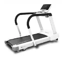
Thank you for your recent purchase of the Philips physical
rehabilitation treadmill, 7.0 T. Philips physical therapy and exercise
solutions provide simple, reliable products that oer the most
relevant feedback to caregivers and users to achieve best-in-class
outcomes and empower individuals to build condence in rebuilding
and maintaining healthy lifestyles and keep in touch with their
communities.
Your new product has been manufactured by one of the world’s
leading medical product manufactures. It is backed by one of the
most comprehensive warranties in the industry. Through our dealers,
distributors and manufacturer’s representatives, we will do all we can
to provide many years of successful and prosperous ownership. Your
warranty and service needs will be addressed either through your
regional sales representative or our highly trained service technicians.
It is their responsibility to provide you with both the technical
knowledge and access to service personnel to make your ownership
experience more informed, and resolve any issues quickly.
Product registration
Register your product and get support at :
www.philips.com/welcome .
This will ensure we have all your details quickly at hand in dealing with
any after sales support. For fastest support visit us online for chat and
self service solution at :
www.philips.com/support .
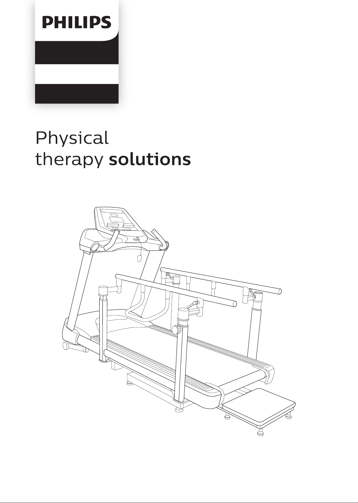
Philips therapy solutions
Delivering better outcomes

Contents
Important safety instructions 5
Important electrical information
Important operation instructions 10
Application specication 11
Operating principle 13
Signicant physical characteristics 13
8
Signicant performance characteristic
14
Intended user prole 15

44
48
59
67
Features 18
Operation of your new treadmill 21
Data transfer software instructions 36
Using a heart rate transmitter 40
Assembly instructions for 7.0 T
Important assembly instructions
Maintenance
71
Specications
Description of packaging symbols
Operating the 7.0 T 16

5
Attention
Read all instructions in this manual before using this device.
Danger
To reduce the risk of electric shock disconnect your treadmill from the
electrical outlet prior to cleaning and/or service work.
Warning
• Do not modify this equipment without authorization of the
manufacturer.
• To reduce the risk of burns, re, electric shock, or injury to persons,
install the treadmill on a at level surface with access to a 115-volt
AC, 60 Hz, 20-amp grounded outlet. Do not use an extension cord
unless it is 12awg or larger, with only one outlet on the end. The
treadmill should be the only appliance in the electrical circuit. Do not
attempt to disable the grounded plug by using improper adapters, or
in any way modify the cord set; a serious shock or re hazard may
result along with computer malfunctions.
• To avoid risk of electric shock, this equipment must only be con-
nected to a supply main with protective earth.
• Use this device only for it’s intended use as described in this
manual.
• Keep children away from the treadmill. There are moving parts,
obvious pinch points and other caution areas that can cause harm.
Important
safety
instructions

6
• Except as instructed for use of the device, keep hands away from all
moving parts.
• Keep the electrical cord away from heated surfaces and out of all
travel lanes and do not operate the treadmill if the cord or plug is
damaged.
• Never drop or insert any object into any openings.
• Do not use outdoors.
• To disconnect, turn all controls to the o position then remove the
plug from the outlet.
• This device is designed for commercial use and will meet the
demands of orthopedic, sports wellness and general conditioning
programs.
• Do not attempt to use your treadmill for any purpose other than for
the purpose it is intended.
•The pulse sensors are not medical devices. Various factors, including
the user’s movement, may aect the accuracy of heart rate readings.
The pulse sensors are intended only as exercise aids in determining
heart rate trends in general.
• Heart rate monitoring system may be inaccurate. Over exercise may
result in injury or death. If you feel faint stop exercising immediately.
• Ensure there is a minimum space on the sides of the treadmill of
two feet for proper operation, easy access and to prevent possible
injuries to others standing or walking nearby. There should be a
minimum of at least one foot of free space at the front and three
and a half feet at the rear.
• Do not use any after market parts on this device, other than those
recommended by Philips.

7
• Do not attempt any servicing or adjustments other than those
described in this manual. All else must be left to trained service
personnel familiar with electro-mechanical equipment and
authorized under the laws of the country in question to carry out
maintenance and repair work.
• Installation and assembly of this product should be performed by
trained personnel only.
• Hold the handlebar for support when getting on or o the treadmill.
• To avoid injury please observe all minimum and maximum
adjustment settings.
• Wear proper shoes. High heels, dress shoes, sandals or bare feet are
not suitable for use on the treadmill. Quality athletic shoes are
recommended to avoid leg fatigue.
• A safety tether cord is provided with this unit. It is a simple magnetic
design that should be used at all times. It is for your safety should
you fall or move too far back on the tread-belt. Pulling this safety
tether cord will stop tread-belt movement.

8
Warning
• Never remove any cover without rst disconnecting AC power. If
voltage varies by 10% or more, the performance of your treadmill
may be aected. Such conditions are not covered under your
warranty. If you suspect the voltage is low, contact your local power
company or a licensed electrician for proper testing.
• Never expose this product to rain or moisture. This product is not
designed for use outdoors, near a pool or spa, or in any other high
humidity environment.
• The treadmill is not protected against the ingress of water or partic-
ulate matter.
• The treadmill is not suitable for use in an oxygen rich environment.
• If not stated otherwise Philips devices are designed for operation in
normal climatic surroundings (IEC 60601-1):
- Temperature: + 10° ... + 36° C
- Relative humidity: 30 ... 90 % (non condensing)
- Air pressure: 700 ... 1060 mbar
- Maximum operating altitude: approx. 10,000 feet (3000m), with
out pressurization
- Transport and store the devices at a temperature of – 20° ...
+ 50° C.
Important
electrical
information

9
Grounding instructions
This product must be grounded. In the unlikely event that the
treadmill’s electrical system should malfunction or breakdown
grounding provides a path of least resistance for electric current,
reducing the risk of electric shock. This product is equipped with a
cord having an equipment-grounding plug. The plug must be plugged
into an appropriate outlet that is properly installed and grounded in
accordance with all local codes and ordinances.
Danger
Improper connection of the equipment-grounding conductor can
result in a risk of electric shock. Check with a qualied electrician or
serviceman if you are in doubt as to whether the product is properly
grounded. Do not modify the plug provided with the product if it will
not t the outlet; have a proper outlet installed by a qualied
electrician.

10
• Never use the treadmill during an electrical storm. Surges may occur
in your facility power supply that could damage the treadmill’s
components.
• All users should have medical clearance before starting any rigorous
exercise program.
• Start the user at a safe exercise level. Do not allow the user to be
over exerted. Symptoms to watch for, but not limited to, are:
Shortness of breath or diculty in breathing, pain or discomfort,
feeling faint.
• Make sure the user warms up and cools down properly to avoid over
taxing the cardio vascular system. Allow three to ve minutes of
warm up and cool down during each exercise session.
Important
operation
instructions

Attention
Read all instructions in this manual before using this device.
Danger
To reduce the risk of electric shock disconnect your treadmill from the
electrical outlet prior to cleaning and/or service work.
Warning
• Do not modify this equipment without authorization of the
manufacturer.
• To reduce the risk of burns, re, electric shock, or injury to persons,
install the treadmill on a at level surface with access to a 115-volt
AC, 60 Hz, 20-amp grounded outlet. Do not use an extension cord
unless it is 12awg or larger, with only one outlet on the end. The
treadmill should be the only appliance in the electrical circuit. Do not
attempt to disable the grounded plug by using improper adapters, or
in any way modify the cord set; a serious shock or re hazard may
result along with computer malfunctions.
• To avoid risk of electric shock, this equipment must only be con-
nected to a supply main with protective earth.
• Use this device only for it’s intended use as described in this
manual.
• Keep children away from the treadmill. There are moving parts,
obvious pinch points and other caution areas that can cause harm.
11
Medical purpose
• Patient warm up before physical therapy session.
• Have the patient walk to improve ambulation and range of motion
after knee/hip/ankle surgery or neurological conditions.
• Allow patients to perform cardiovascular exercise.
Intended patient population
• There is no particular restriction on age, gender, height and nationality.
• Maximal patient’s weight is 200kg.
• Patient must be ambulatory.
• Patient should have medical clearance before starting any rigorous
exercise program. This is especially important for person with a history
of heart disease or other high risk factors.
Intended part of the body or type of tissue applied to or
interacted with:
• Contact site: hands and feet
• Condition: should not have any trauma
Application
specication

12
Intended conditions of use
• Environment including hygienic requirements
- General: intended for indoors use. This product is not designed
for use outdoors, near a pool or spa, or in any other high humidity
environment.
- Conditions of visibility:
Ambient luminance: standard ambient room lighting is
sucient.
Viewing distance: 1 m
Viewing angle: 120°
- Physical
Temperature range: 10°C ~ 36°C
Relative humidity range: 30% R.H. ~ 90% R.H., non condensing
- Hygienic requirements: there is no particular restriction on
hygienic requirements.
• Frequency of use
- Dependent on therapist’s plan.
• Location
- Intended for hospital use, clinic use, home use and research in
academic institutions.
• Mobility
- The product is intended to be xed.
1
1
2
2
3

13
The operator will start the device and use the speed and incline keys
to control motors. When the speed key is pressed a signal is sent to
the AC motor inverter to request a change. The inverter will then send
the appropriate amount of power the AC drive motor to reach the
requested speed. The motor drives the front roller (which in turn
moves the walking belt) through pulleys and fan belt. The incline
motor is operated when the operator presses the incline keys. A
command is generated that is transmitted to the incline control board
where a relay is energized sending AC power to the motor until it
reaches the desired position.
Operating
principle
Please refer to Features of 7.0 T manual.
Signicant
physical
characteristics

14
Please refer to “Unique uses for the 7.0 T” in operating the 7.0 T.
Signicant
performance
characteristic

15
Intended operator
• There is no particular restriction on age, gender, height, weight,
ability and culture.
• Education: University or above
• Knowledge: The operator should read the user’s manual before use.
• Discipline: The operator should receive training from the
manufacturer before use.
• Experience: The operator must have experience in physical therapy.
• Background: The operator must be a major in physical therapy.•
Professional competence: The operator should have the physical
therapist license.
Intended Installer
• There is no particular restriction on age, gender, height, weight,
ability and culture.
• Education: High School or above
• Knowledge: The installer shall be able to manipulate this product
properly.
• Discipline: The installer shall be given a specic training by
manufacturer.
• Experience: The installer must have experience in product assembly
and disassembly.
• Background: The installer must be electro-mechanically trained.
• Professional competence: Normal vision ability required.
Intended
user
prole

16
The treadmill is intended to be used in aiding in the physical
rehabilitation process for patients with orthopedic and neurological
problems. Also used in sports medicine, wellness and general
conditioning programs.
Typical applications for this type of product are
• Patient warm up before physical therapy session.
• Have the patient walk to improve ambulation and range of motion
after knee/hip/ankle surgery or neurological conditions.
• Allow patients to perform cardiovascular exercise
Unique uses for the 7.0 T :
• The walking belt allows for both forward and reverse walking.
• The front and rear incline allows for uphill and downhill walking.
• Symmetry program measures distance between left and right step
lengths. Graphical bio-feedback display motivates patients to
maintain even step symmetry between left and right legs.
Operating
the 7.0 T

17
Other features of the 7.0 T
• Belt speed settings start at 0.1 km/hr.
• The parallel handrails are adjustable to accommodate for pediatric to
large adult sizes.
• Heart rate monitoring using the optional heart rate chest-strap.
Heart rate measurements are not for medical use
The heart rate function on this product is not a medical device and
should not be relied on when accurate readings are necessary. Some
people, including those in a cardiac rehab program, may benet from
using an alternate heart rate monitoring system like a chest or wrist
strap. Various factors, including movement of the user, may aect the
accuracy of your heart rate reading. The heart rate reading is intended
only as an exercise aid for measuring heart rate trends in general.

18
7.0 T – Treadmill
Parts and adjustments
1. Hand grips
2. Electronic console
3. Safety lanyard
4. Adjustable hand rails
5. Handrail horizontal adjustment
6. Handrail vertical adjustment
7. Handrail lift bar
8. Rear step
9. Rear incline
10. Front incline
Features
10
2
3
4
5
6
7
89
1
19
The 7.0 T is an easy product to set up and use, from the adjustments to
the intuitive interface. This section explains how to set up, adjust and
operate your 7.0 T.
Leveling the 7.0 T
Once the 7.0 T is assembled, and placed on a at level oor, it may be
necessary to adjust the four leveling glides on the bottom of the rear
incline unit to ensure proper stability of the 7.0 T. Use a 1/2” wrench
to loosen the top nut of the leveler. Adjust the levelers by hand as
necessary to remove any wobble in the unit. Then tighten the top nut
against the bottom of the stabilizer tube. Make sure the bottom nut
remains cinched against the leveling foot.
Connecting to A.C. power
The 7.0 T A.C. mains input connector is located in the front of the unit.
The input module has an input connector for the line cord, a power
switch and a 20 amp circuit breaker. Turn the power switch to o
when the 7.0 T is not in use.
Lift bar
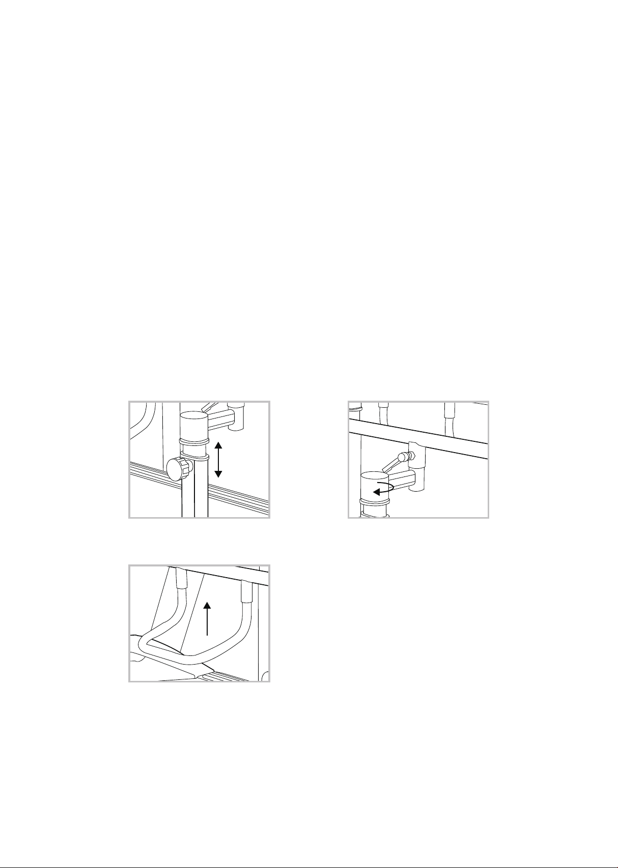
Vertical adjustment Horizontal adjustment

20
Adjusting the hand rail vertical position
• To lift: Turn both the left and right vertical adjustment knobs
counterclockwise one or two rotations. Then just grab the lift bar
and pull up. The locking pins in the knobs will automatically ratchet
into the indexing holes in the tubes. Tighten the knobs when
desired position is set. There is a numbered scale on the tubes for
repeatable settings.
• To lower: Loosen the two knobs and then pull them out and rotate
slightly until the knob remains out on its own. The pin should now
be disengaged from the tube and you can use the lift bar to lower
the rails. Lower the rail past the position you desire and rotate the
knob again so the pin can engage the holes in the tube. Now lift the
rails to the desired position and lock the knob.
Adjusting the hand rail horizontal position
Turn both the left and right levers counterclockwise one rotation.
Move the rails to the desired position and re-lock the levers. There
are numbered scales on the tubes for repeatable settings. The levers
may be blocked by the rotating tube when position is changed. The
levers can be repositioned by pulling out and rotating them to a new
position, allowing tightening.
Lift bar
The lift bar will make raising and lowering the hand rails easier. You
can remove the lift bars for better patient access by loosening the
locking knobs. Hold the bar with one hand and loosen the knobs with
the other so the lift bar does not suddenly fall to the oor.
Rear step
Additional step lowers the step-up height to 4 inches. To install or
remove the step easily there are two removable pins located under
the rear of the treadmill. Be sure these two pins are in place before
using.
21
7.0 T electronic console
Power on
When initially powered on the console will perform an internal
self-test. During this time all the lights will turn on for a short time.
The message window will display a software version (i.e. VER 1.0) and
the distance window will display an odometer reading indicating how
many virtual miles (or Kilometers) the treadmill has gone.
The time window displays how many hours the treadmill has been
used.
Operation
of your
new treadmill
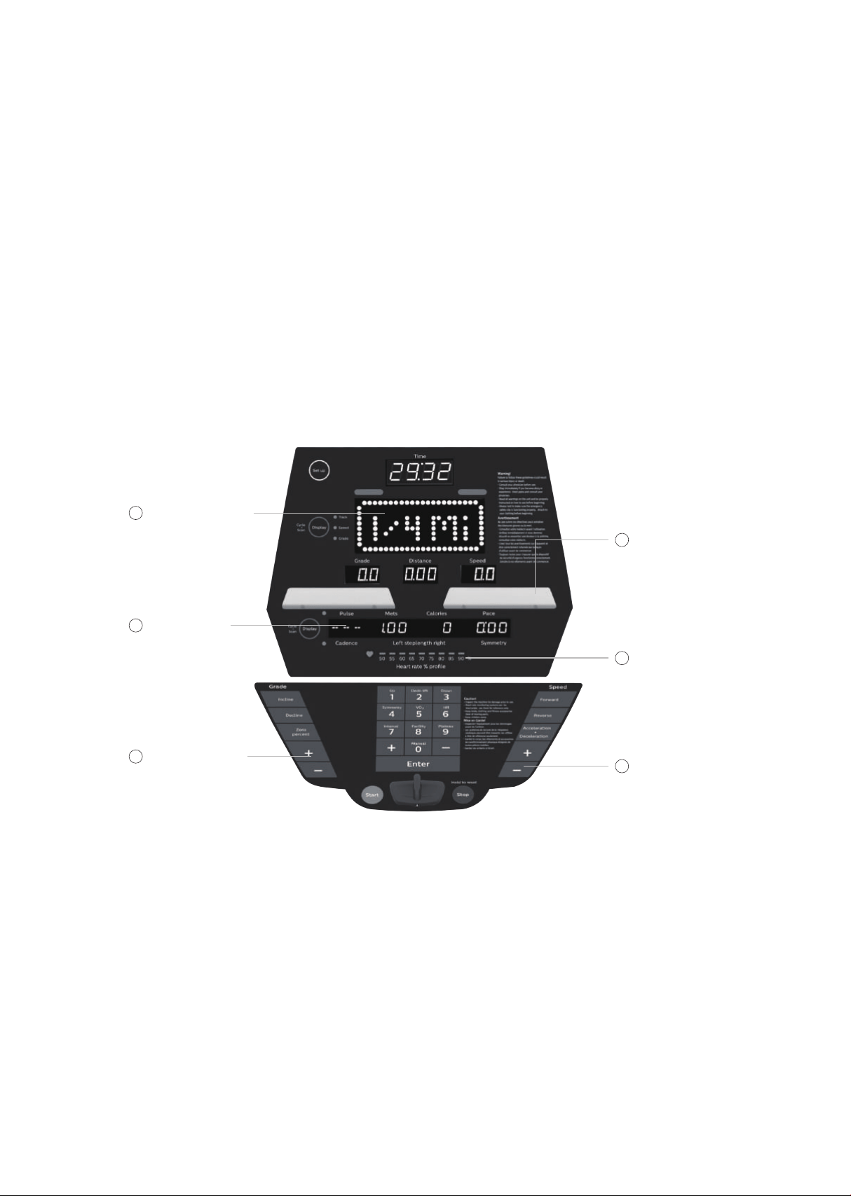
Large LED matrix
window
16-character
messsage center
Incline buttons
Tablet friendly
reading rack
holder
Heart rate %
prole
Speed buttons
1
2
3
4
5
6

22
The odometer will remain displayed for only a few seconds then the
console will go to the start up display, also known as Idle Mode. The
message window will be scrolling the start up message. You may now
begin to use the 7.0 T.
The console will automatically power down after 30 minutes of
inactivity. Press any key to wake the console up again. To disable this
function so console always remains powered on see Maintenance
section on page 58. Always turn o the main power switch when the
7.0 T is not in use.
Console operation
Set up
The set up key function will allow you to enter patient data and
customize the settings of the 7.0 T. When the set up key is pressed
the rst option in the menu appears. Use the up/down arrows to
scroll through the menu and press the enter key to select an option.
Set up menu
• Patient data
- Age : used in VO2 and heart rate programs.
- Gender : used in VO2 program.
- Weight : used in METS and calorie calculations and VO2 program.
- Height : used in the Symmetry program.
Quick start
This is the quickest way to start an exercise session. After the console
powers up you just press the Start key to begin; this will initiate the
Quick Start mode. In Quick Start the speed will be set to zero until
the user adjusts the speed. Time will count up from zero, all workout
data will start to accrue and the speed and incline may be adjusted
manually by pressing the Up or Down key. The dot matrix will display
a speed level. As you increase the speed more rows will light
indicating a harder workout.

23
The dot matrix has 24 columns of lights and each column represents 1
minute in the Quick Start program (time per column can be modied
in other programs). At the end of the 24th column (or 24 minutes of
work) the display will wrap around and restart at the rst column
again.
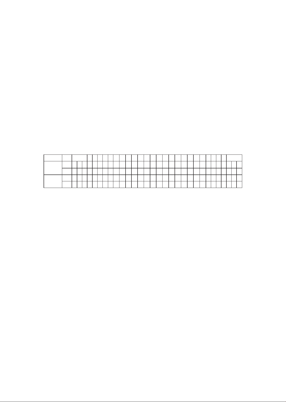
Basic information
The dot matrix display is used for displaying graphic feedback and
has three basic displays for most programs. When you begin a
program the dot matrix will display a speed prole. To the left of the
dot matrix there is a key labeled display. Pressing this key will switch
the display to show an incline grade and then a track. When the LEDs
are blinking the graph will scan through the three displays.
The four data windows display:
• Time: Program time remaining, or elapsed time in quick start mode.
• Incline grade: Front incline range 0 to 15 %. Rear incline range 0 to
minus 10%
• Distance: Displayed in miles or kilometers, selected in Maintenance
mode (see page 58).
• Speed: Displayed in mph or kph. Range from minus 3 mph (5 kph) to
plus 10 mph (16 kph) in 0.1 increments. True zero speed provided by
a mechanical brake when ever motor is idle.
The message window is the main display for programming
instructions and relevant measurements during a program.
The measurement data shown varies depending on the program.
Measurements include:
• Pulse: Heart rate monitor displayed in beats per minute, from 0 to
240 bpm.
• METS: Metabolic equivalent; values of activities range from 0.9
(sleeping) to 23 (running at 22.5 km/h or a 4:17 mile pace).
• Calories: Or kilocalorie (kcal), nutritional Calories burned during
exercise.
• Pace: Displayed as minutes per mile (or kilometer).
• Step cadence: Steps per minute average.
• Step length: Heel strike to heel strike step length in inches or
centimeters.
• Symmetry: The percentage of dierence between the left and right
step length.

24
To the left of the message window is a display key that allows you to
switch the data shown.
Below the message window is a heart icon and a bar graph. Wearing
an optional heart rate chest belt transmitter will start the Heart Icon
blinking (this may take a few seconds). The message window will
display your heart rate in beats per minute. The bar graph represents
the percentage of maximum heart rate.
Note: Enter the correct age in set up for the bar graph to be
accurate. Refer to heart rate section for details about these
features.
Function keys
The stop/reset key provides several functions:
• Pressing the stop/reset key once during a program will pause the
program. To resume the exercise session just press the start key.
• If the stop/reset button is pressed twice during a workout ends the
program and a summary of information for the exercise session will
be displayed.
• If the stop/reset key is held down for 3 seconds the console will
perform a complete reset.
• During data entry for a program the stop/reset key performs a
previous screen function. This allows you to go back one step in the
programming each time you press the stop/reset key.
The program keys may be used to preview each program when in the
idle mode. Press each program key to preview the program prole. To
begin a program press the corresponding program key and then press
the enter key to select the program.
The program keys also function as a number key pad when you are in
the data-setup mode. The number for each key is shown below the
program name. If you are entering new data such as time, age, weight
etc., you can use these keys to enter the numbers quickly.

25
Forward
This key sets the belt direction to forward. Forward is the default
direction setting when the treadmill is powered on and any time the
console is in the idle mode. If the belt is already set in the reverse
direction, it will change the direction of the belt to forward. If the belt
is moving in reverse when the key is pressed the belt will slow down
to zero speed and then speed changes in the forward direction are
allowed.
Reverse
This key sets the belt direction to reverse if the belt is already set to
forward direction. This function only operates in quick start or manual
mode. If the belt is moving when the key is pressed the belt will slow
down to zero speed then allow speed changes in the reverse
direction. The speed window will show a minus (-) sign indicating the
speed is set to reverse.
Acceleration - Deceleration
This function adjusts the acceleration and deceleration rate of the
walking belt by allowing you to change the amount of time it takes for
the belt to change speeds. The adjustment value is in seconds. You
can input how many seconds it takes for the belt to change 1 mph of
speed. The default setting is 3 seconds, which means the belt will
take 3 seconds to go from zero to 1 mph. The range can be set from 1
second to 60 seconds. This function can be disabled in the
Maintenance mode (see page 58).
Incline
Press this key to return to front incline function if decline function is
active.

26
Decline
Allows operation of the rear deck motor for decline function. This key
only operates in quick start or manual modes. When the function is
active the grade window will show a minus (-) sign indicating the
grade is set for decline.
Zero Percent
Returns the deck to zero percent when pressed.
Deck-lift program
This program allows you to raise the entire deck parallel to the oor.
In this mode the deck, rear step and hand rails can be used for
step-up, step-down, stretching and PNF/PTA exercises.
Lifting the deck while a patient walks allows the therapist to assist
the patient by moving their legs without having to bend over too far.
The deck-lift program is also used with the basic un-weighting
system. Raise the deck and connect the patient’s un-weighting
harness to the un-weighting system. The up and down keys can be
used to raise or lower the deck for un-weighing the patient.
• Instructions for raising and lowering the deck
Press the deck-lift key to activate the program.
• The grade window will display 01 which indicates the rst level. The
starting height from the step to the deck at level 1 is 5.25 inches
(13.34cm). The height will be displayed in the message window. The
height from the oor to the step is 4 inches (10 cm).
• Press the up and down keys to raise and lower the deck. There are
30 levels available with each level raising the deck ¼ inch (6.35mm).
At level 30 the deck height is 12.5 inches (31.75cm) from the step.
Note that the measurements are approximate.
• In the deck-lift program you can press the start key and the
treadmill will function normally as if in manual mode.
• When the stop key is pressed you will be prompted to conrm the
deck will be returned to the lowest level. This ensures that the deck
does not automatically lower itself to level one when a patient is
connected to the un-weighting system.
Up
1
Deck-lift
2
Down
3

27
Selecting and customizing programs
When a program is selected you have the option of modifying the
settings. If you want to begin without entering new settings just press
the start key. This will bypass the programming of data and take you
directly to the start of the program. If you want to change the settings
just follow the instructions in the message window. When you start a
program the data from the set up menu will be used.
Manual
The manual program works as the name implies, manually. This
means that you control the workload yourself, not the computer. To
start the manual program follow the instructions below or just press
the manual button then the enter button and follow the directions in
the message window.
• Press the manual key then press the enter key.
• The message window will prompt you to enter the time for the
program. You may enter the time using the up and down keys or the
numeric key pad then press the enter key to accept.
• Now you are nished editing the settings and can begin the
program by pressing the start key. All data calculations will use the
patient information from the set up function (set up key at top left
of console).
• During the manual program you will be able to scroll through the
data in the message window by pressing the display key. You may
also switch between the speed, incline or track displays by
pressing the display key adjacent to the dot matrix display.
• When the program ends you may press start to begin the same
program again or top to exit the program, or you can save the
program you just completed as the facility program by pressing the
facility key and following the instructions in the message window.
Preset programs
The treadmill has two preset exercise programs that have been
designed for a variety of goals. The initial built-in level of diculty for
each program is set to a relatively easy level. You may adjust the level
of diculty (max speed) for each program before beginning.
28
The proles shown in the dot matrix are merely pictures of the whole
prole and will not change in size when the speed keys are pressed.
When setting up a program you will enter the maximum speed setting
for the peak of the prole. During the program the speed levels will
change as the prole progresses. When the up key is pressed to
request more speed the prole picture will not change, but the speed
will increase. Pressing the speed keys actually change the peak level
of the program not the current segment speed. You may need to
change the peak setting several times by pressing the speed key
before the current segment increases.
Preset programs speed and incline settings
The preset program speed and incline levels are shown in the chart
below. The Speed numbers shown in the chart indicate a percentage
of the top speed of the program.
Programming preset programs
• Select a program then press the enter key to begin customizing the
program settings, or just press the start key to begin the program
with the default settings. All data calculations will use the patient
information from the set up function (set up key at top left of con-
sole).
• After selecting a program, press enter to set the program time. The
Time window will blink with the default value of 30 minutes. You
may use any of the up/down keys to adjust the time. After adjusting
the time, press enter. (Note: You may press start at any time during
the programming to begin with only settings you have modied at
that point).
• The speed window will now be blinking, showing the preset top
speed of the selected program. Use the up/down keys to adjust,
and then press enter. Each program has various speed changes
throughout; this allows you to limit the highest speed the program
will attain during your workout.
Prog SEG Warm up 1 2 3 4 5 6 7 8 9 10 11 12 13 14 15 16 17 18 19 20 21 22 23 24 Cool down
Plateau
Speed 20 30 40 50 60 60 70 80 100 100 100 100 100 100 100 100 100 100 100 100 100 100 100 80 70 60 50 40 30 20
Incline 0 0 0 0 0 0 0 0 0 0 0 0 0 0 0 0 0 0 0 0 0 0 0 0 0 0 0 0 0 0
Interval
Speed 20 30 40 50 60 60 70 80 100 60 60 70 80 100 60 70 100 60 70 100 60 70 80 70 60 60 50 40 30 20
Incline 0 0 0 0 1 2 3 5 6 2 3 5 6 7 2 3 7 2 3 8 2 3 5 4 3 1 0 0 0 0

29
• Now press the start key to begin your workout.
• There will be a 3 minute warm-up to begin. You can press the start
button to bypass this and go straight to the workout. During the
warm-up the clock will count down from 3 minutes.
Facility program
The facility program allows you to build and save a custom program.
You can build your own custom program by following the instructions
below or you can save any other preset program you complete as a
custom program. The facility program allows you to further
personalize it by adding your facility name.
Designing and saving a new program
• Press the facility key. The message window will show a welcome
message; if you had previously saved a program the message will
contain the name you gave it. Then press the Enter key to begin
programming.
• When you press enter, the message window will show “Name – A”, if
there is no name saved. If the name “Custom Workout” had been
previously saved the message window will show “Name – Custom
Workout” and the C in Custom will be blinking. If there is a name
saved you can change it or you may press the stop key to keep the
name and continue to the next step. If you want to enter a name
use the up and/or the down key to change the rst letter then press
enter to save the rst letter and continue to the next letter. When
you have nished entering the name press the stop key to save the
name and continue to the next step.
• The message window will ask you to enter an age. You may enter an
Age, using the up and down keys or the numeric key pad, then press
the enter key to accept the new number and proceed on to the next
screen.
• You are now asked to enter a weight. You may adjust the weight
number using the up and down keys or the numeric key pad then
press enter to continue.
• Next is time. You may adjust the time and press enter to continue.

30
• Now you are asked to adjust the max level. This is the peak
exertion level you will experience during the program. Adjust the
level and then press enter.
• Now the rst column will be blinking and you are asked to adjust
the level for the rst segment of the workout. When you nish
adjusting the rst segment, or if you don’t want to change, then
press enter to continue to the next segment.
• The next segment will show the same level as the previously adjust-
ed segment. Repeat the same process as the last segment then
press enter. Continue this process until all twenty four
segments have been set.
• The message window will then tell you to press enter to save the
program. After saving the program the message window says “New
program saved” then will give you the option to start or modify the
program. Pressing stop will exit to the start up screen.
• During the gacility program you will be able to scroll through the
data in the message window by pressing the adjacent Display key.
Running a saved program
• Press Facility key then Enter
• Enter Time then press enter. Then press start to begin program.

31
VO2 test
The VO2 test is based on the Gerkin protocol, also known as the
reman’s protocol, and is a sub-max VO2 (volume of oxygen) test. The
test will increase speed and elevation alternately until 85% of Max
heart rate is attained. The time it takes the heart rate to reach 85%
determines the test score (VO2max) as shown in the chart below.
Stage Time Speed Grade VO2max
1 0 to 1:00 4.5mph 0% 31.15
2.1 1:15 4.5mph 2% 32.55
2.2 1:30 4.5mph 2% 33.6
2.3 1:45 4.5mph 2% 34.65
2.4 2:00 4.5mph 2% 35.35
3.1 2:15 5.0mph 2% 37.45
3.2 2:30 5.0mph 2% 39.55
3.3 2:45 5.0mph 2% 41.3
3.4 3:00 5.0mph 2% 43.4
4.1 3:15 5.0mph 4% 44.1
4.2 3:30 5.0mph 4% 45.15
4.3 3:45 5.0mph 4% 46.2
4.4 4:00 5.0mph 4% 46.5
5.1 4:15 5.5mph 4% 48.6
5.2 4:30 5.5mph 4% 50
5.3 4:45 5.5mph 4% 51.4
5.4 5:00 5.5mph 4% 52.8
6.1 5:15 5.5mph 6% 53.9
6.2 5:30 5.5mph 6% 54.9
6.3 5:45 5.5mph 6% 56
6.4 6:00 5.5mph 6% 57
7.1 6:15 6.0mph 6% 57.7
7.2 6:30 6.0mph 6% 58.8
7.3 6:45 6.0mph 6% 60.2
7.4 7:00 6.0mph 6% 61.2
8.1 7:15 6.0mph 8% 62.3
8.2 7:30 6.0mph 8% 63.3
8.3 7:45 6.0mph 8% 64
8.4 8:00 6.0mph 8% 65
9.1 8:15 6.5mph 8% 66.5
9.2 8:30 6.5mph 8% 68.2
9.3 8:45 6.5mph 8% 69
9.4 9:00 6.5mph 8% 70.7
10.1 9:15 6.5mph 10% 72.1
10.2 9:30 6.5mph 10% 73.1
10.3 9:45 6.5mph 10% 73.8
10.4 10:00 6.5mph 10% 74.9
11.1 10:15 7.0mph 10% 76.3
11.2 10:30 7.0mph 10% 77.7
11.3 10:45 7.0mph 10% 79.1
11.4 11:00 7.0mph 10% 80

32
Before the test
• Make sure you are in good health; check with your physician before
performing any exercise if you are over the age of 35 or persons with
pre-existing health conditions.
• Make sure you have warmed up and stretched before taking the test.
• Do not take in caeine before the test.
Fitness test programming
• Press the VO2 key and press enter.
• The message window will ask you to enter your age. You may adjust
the age setting, shown in the Incline window, using the up and
down keys then press the enter key to accept the new number and
proceed on to the next screen.
• You are now asked to enter your Weight. You may adjust the weight
setting, shown in the distance window, using the up and down keys
then press enter to continue.
• Now press start to begin the test.
During the test
• The console must be receiving a steady heart rate for the test to
begin. You may wear a heart rate chest strap transmitter.
• The test will start with a 3 minute warm-up at 3 mph (4.8 kph)
before the actual test begins.
• The data shown during the test is:
- Time indicates total elapsed time.
- Incline in percent grade.
- Distance in Miles or Kilometers depending on preset parameter.
- Speed in mph or kph depending on preset parameter.
- Target Heart Rate and Actual Heart Rate are shown in the message
window.
After the test
• Cool down for about one to three minutes.
• Take note of your score because the console will automatically return to
the start-up mode after a few minutes.

33
What the score indicates:
VO2max chart for males and very t females
VO2max chart for females and de-conditioned males
years
old
years
old
years
old
years
old
years
old
years
old
Excellent >60 >56 >51 >45 >41 >37
Good
52-60
49-56
43-51 39-45 36-41 33-37
Above
average
47-51 43-48 39-42 35-38 32-35 29-32
Average 42-46 40-42
35-38 32-35 30-31 26-28
Below
average
37-41 35-39 31-34
29-31
22-25
Poor
30-
36
30-34
26-30
25-28 22-25 20-21
Very
poor
<30 <30 <26 <25 <22 <20
18-25 26-35 36-45 46-55 56-65 65+
26-
29
years
old
years
old
years
old
years
old
years
old
years
old
Excellent 56 52 45 40 37 32
Good
47-56
45-52
38-45 34-40 32-37 28-32
Above
average
42-46 39-44 34-37 31 -33 28-31 25-27
Average 38-41 35 -38
31 -33 28-30 25 -27 22-24
Below
average
33-37 31 -34 27-30 25-27
22-
24 19-22
Poor
28-
32
26-30
22-26
20-24 18 -21 17 -18
Very
poor
<28 <26 <22 <20 <18 <17
18-25 26-35 36-45 46-55 56-65 65+

34
Symmetry
The symmetry program provides basic gait information and a
feedback graph. The program will measure the left and right step
length and calculates the symmetry index. The message window will
display the user’s cadence, left and right step length in inches (or
centimeters) and symmetry index.
The dot matrix display will show a graph indicating step symmetry so
the user has a visual feedback to aid in improving their gait. If the
user has a longer step length with their left leg the graph will increase
in size on the left of the dot matrix as shown below.
When the program ends, either by the set time reaching zero or
pressing stop twice at any time during the program, a summary is
shown in the message window. The summary gives the average
cadence, step lengths and average symmetry for the amount of time
the user walked.
• Press the symmetry key then press the enter key.
• The message window will prompt you to enter the time for the
program. You may enter the time using the up and down keys or the
numeric key pad then press the enter key to accept and proceed to
the next screen.
• Now you are nished editing the settings and can begin by pressing
the Start key. All data calculations will use the patient information
from the set up function (set up key at top left of console).
• During the program you will be able to scroll through the data in the
message window by pressing the display key.
• When the program ends you may press start to begin the same
program again or stop to exit the program, or you can save the
program you just completed as the facility program by pressing the
facility key and following the instructions in the message window.
35
Biofeedback graph
Below is a sample picture showing the symmetry graph. In the
message window there is an average step cadence, left and right step
length and symmetry measurements. In the example below the step
length numbers shown indicate that the left leg is stepping longer
than the right leg, 26 vs. 15 inches. The graph reects the longer stride
of the left leg. If the step length was even only two dots would be lit
on the bottom center of the graphic screen.
Note: For some types of gaits it may be possible that the left/right
data can be displayed in reverse. If this occurs press the symmetry
program key to ip the display.

36
• Works with newer 7.0 T, 7.0 S, 7.5 S, 7.0 R and 7.0 U consoles with
USB ports on the back
• The software works with Windows 10, 7 and XP series, with .Net •
Framework 2.0.
• The output for the data is in a .CSV le format.
• http://www.dyaco.com/software
Please follow the website instructions to download software.
• Use a USB cable (type a to type b, illustrated to the right) to con-
nect the product and the computer.
Step 1.
Download the software from the link (http://www.dyaco.com/soft-
ware) and connect the console of the product to the computer via
USB cable. Click "Install" when you see the pop-up window as below
during installation.
Data transfer
software
instructions

37
Step 2.
Click "Connect" or "Change" to select the connecting port (left gure).
After clicking the "Change", or connecting to the wrong port, the COM
port selection window pops up (right gure). Select the correct COM
port and click "Connect".
Selecting COM port
Pop-Up COM Port Selection Window
38
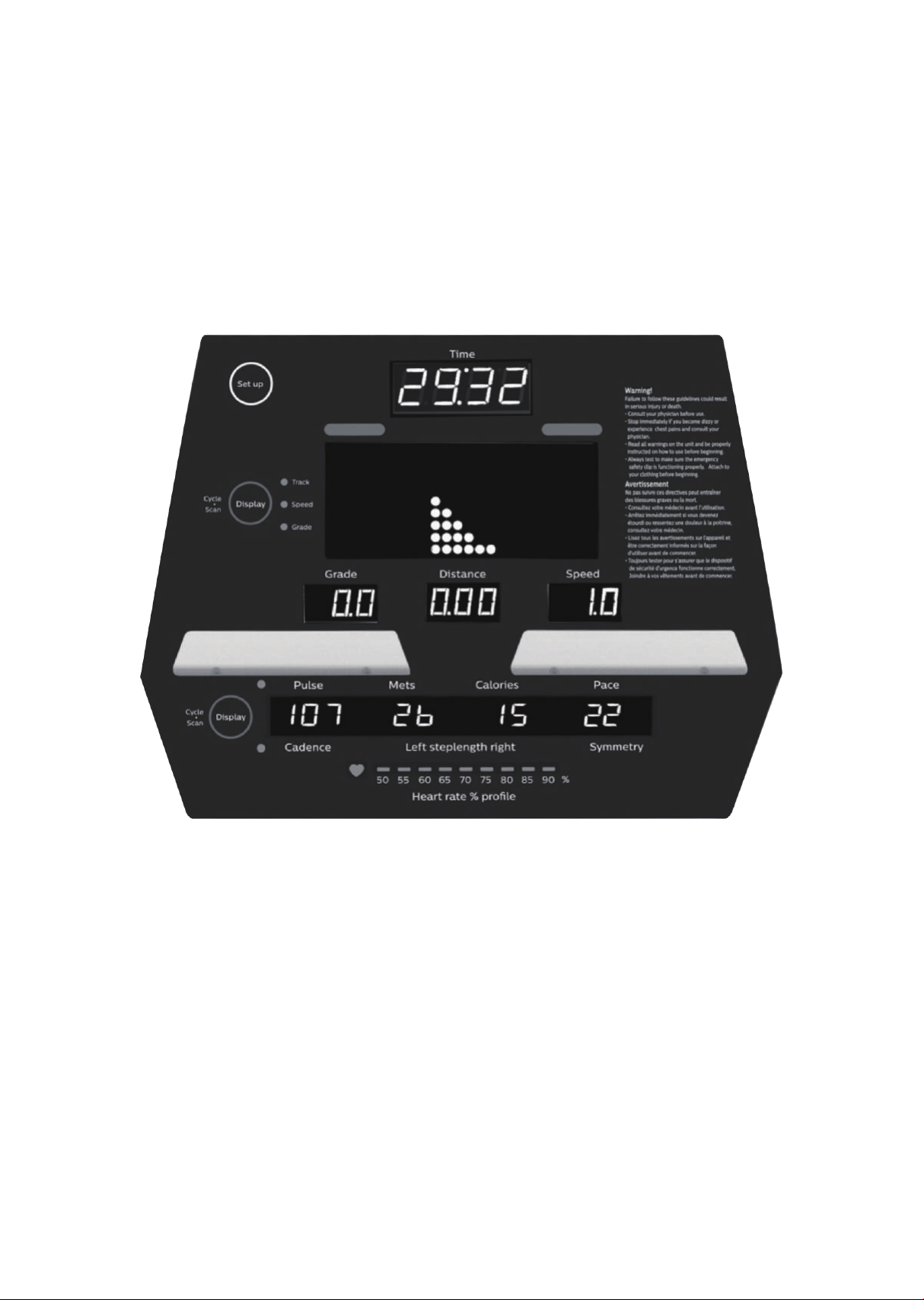
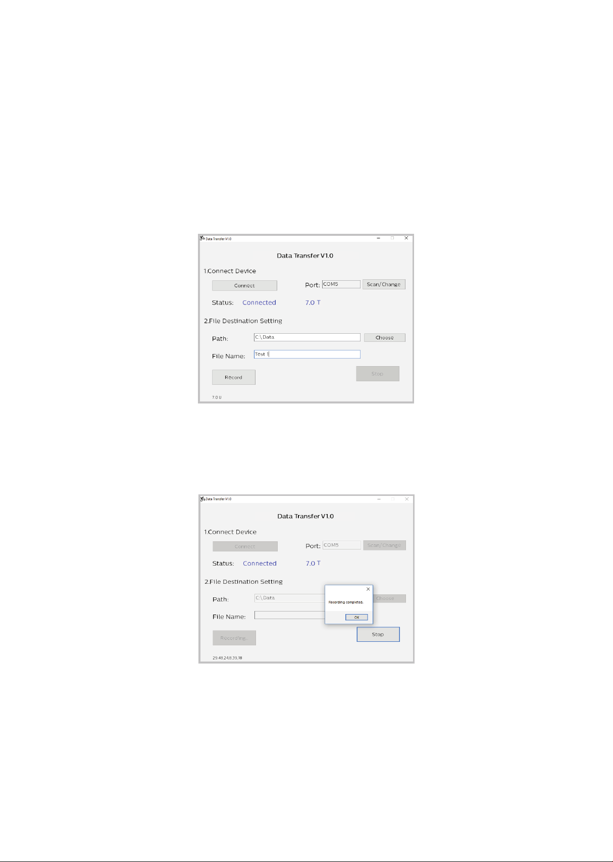
Step3.
After the status shows “Connected” and the product model name to
the right, choose the le path and create the le name for saving the
data. Click the “Record” button to start collecting data. Click “Stop” or
quit the program from the console of the product to stop the data
collection process. The saved data can be found at the assigned
destination.
Click record button
Recording complete
Philips Data Transfer V1.0
Philips Data Transfer V1.0
Philips Data Transfer V1.0
Philips Data Transfer V1.0
T
T

39
The le is saved in .CSV format, which can be opened by Microsoft
Excel. Example shown below.

40
Note: The chest strap transmitter is not a standard part, but is a
separate purchase.
Most transmitters that operate at 5kHz frequency will also work.
How to wear your wireless chest strap transmitter?
• Attach the transmitter to the elastic strap using the locking parts.
• Adjust the strap as tightly as possible as long as the strap is not too
tight to remain comfortable.
• Position the transmitter with the logo centered in the middle of your
body facing away from your chest (some people must position the
transmitter slightly left of center). Attach the nal end of the elastic
strap by inserting the round end and, using the locking parts, secure
the transmitter and strap around your chest.
• Position the transmitter immediately below the pectoral muscles.
Using
a heart rate
transmitter

41
• Sweat is the best conductor to measure very minute heart beat
electrical signals. However, plain water can also be used to pre-wet
the electrodes (2 black square areas on the reverse side of the belt
and either side of transmitter). It’s also recommended that you wear
the transmitter strap a few minutes before your work out. Some users,
because of body chemistry, have a more dicult time in achieving a
strong, steady signal at the beginning. After “warming up”, this problem
lessens. As noted, wearing clothing over the transmitter/strap doesn’t
aect performance.
• Your workout must be within range - distance between transmitter
/ receiver – to achieve a strong steady signal. The length of range may
vary somewhat but generally stay close enough to the console to
maintain good, strong, reliable readings. Wearing the transmitter
immediately against bare skin assures you of proper operation. If you
wish, you may wear the transmitter over a shirt. To do so, moisten the
areas of the shirt that the electrodes will rest upon.
Note: The transmitter is automatically activated when it detects
activity from the user’s heart. Additionally, it automatically deacti-
vates when it does not receive any activity. Although the transmitter
is water resistant, moisture can have the eect of creating false sig-
nals, so you should take precautions to completely dry the transmit-
ter after use to prolong battery life (estimated transmitter battery life
is 2500 hours). If your chest strap has a replaceable battery the
replacement battery is CR2032.
!

42
Erratic operation
Caution! Do not use this treadmill for Heart Rate Control unless a
steady, solid Actual Heart Rate value is being displayed. High, wild,
random numbers being displayed indicate a problem.
Areas to look at for interference, which may cause erratic heart rate
• Microwave ovens, TVs, small appliances, etc.
• Fluorescent lights.
• Some household security systems.
• Perimeter fence for a pet.
• Some people have problems with the transmitter picking up a signal
from their skin. If you have problems try wearing the transmitter upside
down. Normally the transmitter will be oriented so the logo is right side
up.
• The antenna that picks up your heart rate is very sensitive. If there is an
outside noise source, turning the whole machine 90 degrees may
de-tune the interference.
• If there is another person wearing a chest strap within 1 meter, it will
interfere.
• If you continue to experience problems contact your dealer.
Heart rate program operation
To start the HR program follow the instructions below or just press
the HR key then the Enter button and follow the directions in the
message window.
• Press the HR key then press the Enter key.
• The message window will ask you to enter your Age. You may enter
your Age, using the Up and Down keys or the numeric key pad, then
press the Enter key to accept the new number and proceed on to the
next screen.

43
• You are now asked to enter your Weight. You may adjust the Weight
number using the Up and Down keys or the numeric key pad, then
press enter to continue.
• Next is Time. You may adjust the Time and press enter to continue.
• Now you are asked to adjust the Heart rate Level. This is the heart rate
level you will experience during the program. Adjust the level and then
press enter.
• Now you are nished editing the settings and can begin your workout
by pressing the Start key. You can also go back and modify your
settings by pressing the Enter key. NOTE: At any time during the
editing of data you can press the Stop key to go back one level, or
screen.
• If you want to increase or decrease the workload at any time during the
program press the Up or Down key. This will allow you to change your
target heart rate at any time during the program.
• During the HR program you will be able to scroll through the data in
the message window by pressing the adjacent Display key.
• When the program ends you may press Start to begin the same
program again or Stop to exit the program or you can save the
program you just completed as a custom user program by pressing the
Facility key and following the instructions in the message window.
44
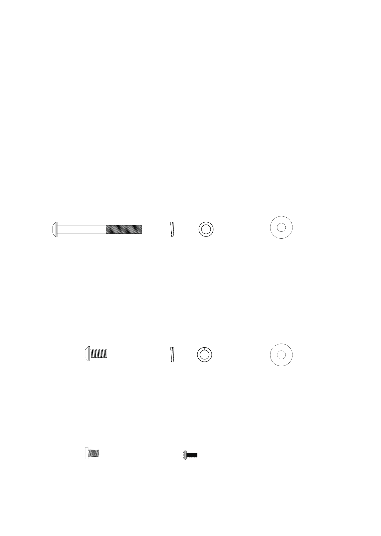
Hardware
Step 1.
Step 2.
Assembly
instructions
for 7.0 T
#104-3/8" x 3-3/4"
(6PCS)
#58-3/8" x 2T x 4H
(6PCS)
#59-3/8" x 25 x 2T
(6PCS)
#153-3/8" x 3/4"
(6PCS)
#58-3/8" x 2T x 4H
(6PCS)
#104-3/8" x 3-3/4"
(6PCS)
#73-M5 x12L
(6PCS)
#59-3/8" x 25 x 2T
(6PCS)
45
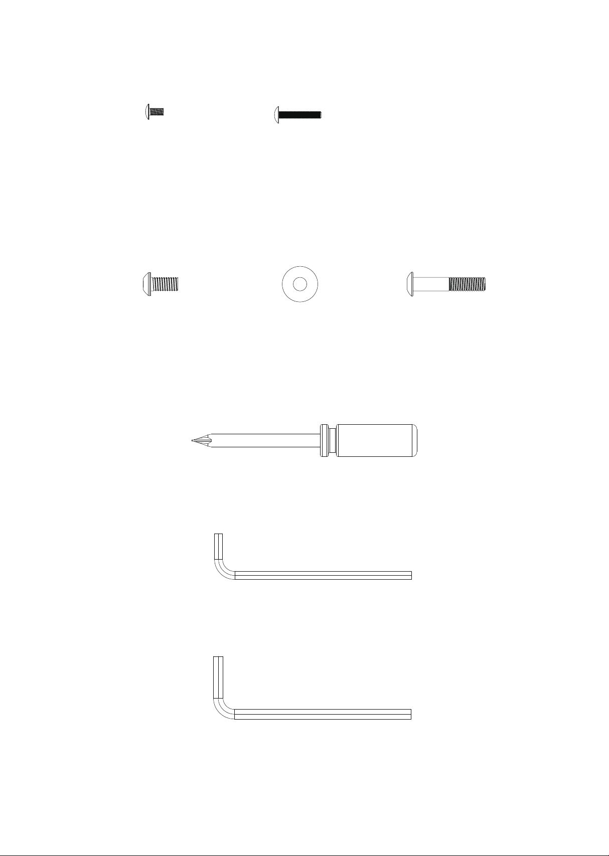
Step 3.
Step 4.
Tools
#110-M5 x 10L
(6PCS)
#112-M5 x 30L
(6PCS)
#153-3/8" x 3/4"
(6PCS)
#59-3/8" x 25 x 2T
(6PCS)
#226-3/8" x 2"
(6PCS)
#113-Philips screw driver
(1PCS)
#137-5mm Allen wrench
(1PCS)
#259-6mm Allen wrench
(1PCS)
46
Assembly
Read each step’s instructions and study the drawing carefully to become
familiar with all the parts and procedures before beginning each step.
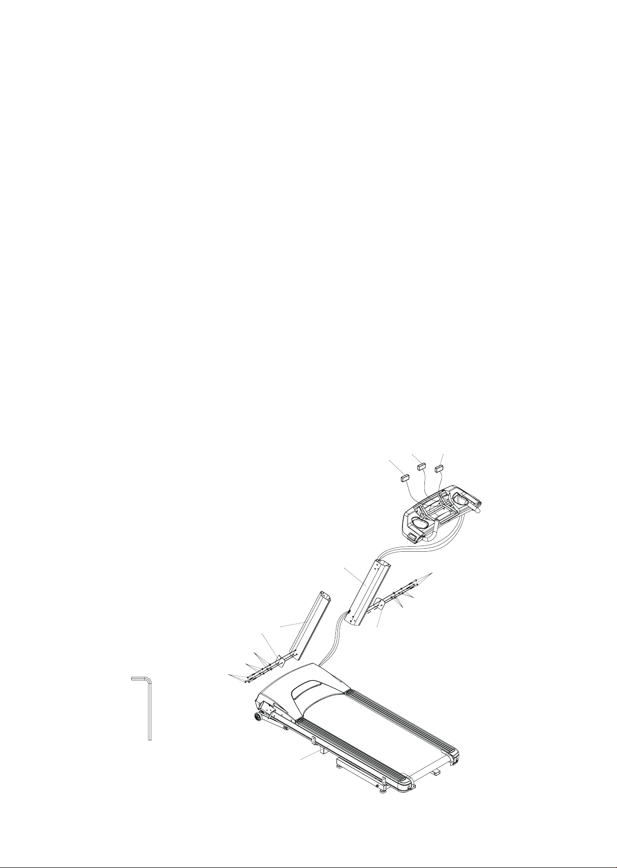
Step 1. Upright tubes
• The right side upright tube (19) has the computer cables pre-installed.
Lift the tube o the walking surface and attach it to the base frame.
You need to gently pull on the computer cables as you align the
upright tube into the bracket on the base frame, taking the slack out
so the cable does not get pinched between the tube and the base
frame. Assemble one 3/8” x 3-3/4” bolt (104), 3/8” split washer (58)
and 3/8” at washer (59) through the top hole in the retaining plate
(21), and corresponding top hole in the upright tube, and screw into the
base frame. Now install the other two bolts (104) and washers (58 & 59)
and hand tighten all three. Do not torque the bolts yet until the upper
console frame is installed.
• Install the left upright (18) in the same manner.
18
19
20
104
59
58
21
59
58
104
1
285
282 284
259
47
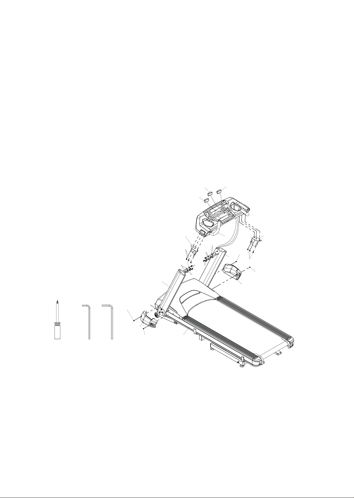
Step 2. Console frame assembly
• Install the two mounting brackets (3 & 4) with the six M8 x 12mm
screws (108). Refer to the important instructions on the following page
for this step.
• Mount the console frame (5) to the upright tubes (18 & 19) with six 3/8”
x 3/4” bolts (153), 3/8” split washers (58) and 3/8” at washers (59). Be
careful not to pinch the computer cables.
• Firmly tighten the six bolts (104) at the bottom of the uprights and
install the two end caps (32 & 33) with the four M5 x 12mm screws (73).
113 137 259
153
58
59
59
58
58
108
3
4
108
73
73
32
33
73
73
104
5
18
19
1
285
282
284
48
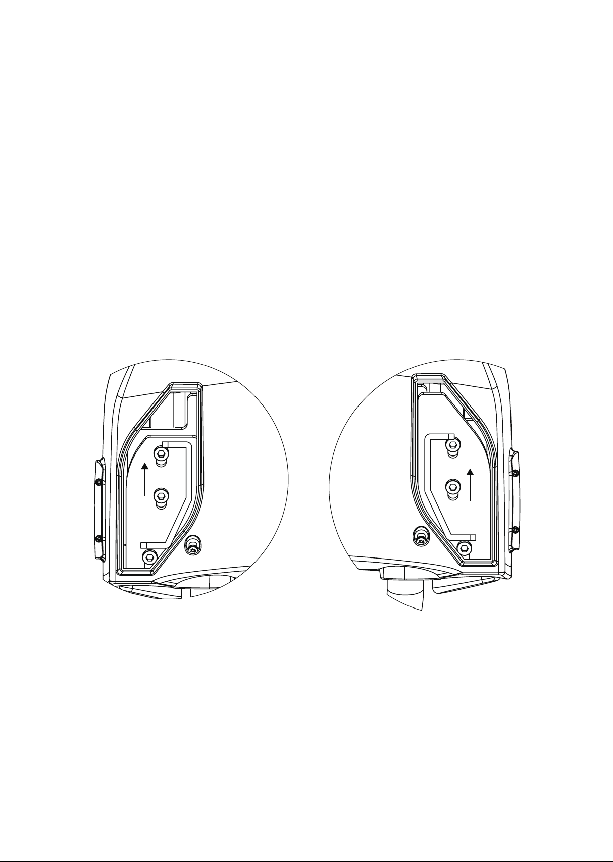
When assembling the console mounting brackets (Items 3&4) please
be sure to slide the brackets all the way towards the back of the
console frame before tightening the bolts.
Push mounting bracket all the way towards the back of the console,
then tighten screws.
Important
assemble
instructions
49
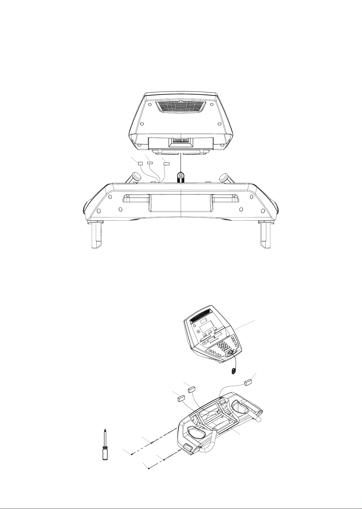
Step 3. Console assembly
• Plug all the connectors in back of the console.
• Mount the console (36) to the console frame (5) with two M5 x 30mm screws (112) in
the top holes and two M5 x 10mm screws (110) in the bottom holes in the back side of
the console frame.
285
282
284
36
285
282
284
5
112
112
110
110
113

50
Step 4. Parallel bar handrail assembly
• Install the eight 3/8” x 3/4” bolts (153) and 3/8” at washers (59) into
the holes on the underside of the frame. Only thread them into the
holes two or three turns so the slots in the handrail brackets can slide
onto the bolts easily. Slide the handrail onto the bolts and hand-
tighten them. Thread the eight 3/8” x 2” bolts (226) into the sides of
the handrails. Once all the bolts are installed tighten all of them
securely.
• Install the Lift Bars (192) to the parallel bars and secure with the knobs
(207).
• Install the rear step (181) by sliding into the receiving tubes under the
rear of the deck and secure with the two pins (217). Raising the rear
incline may make it easier to line up the holes for the pins.
137 259
1
181
192
207
207
226
59
153
59
226
153
217
217
192
207
207
226
226
59
153
153
59
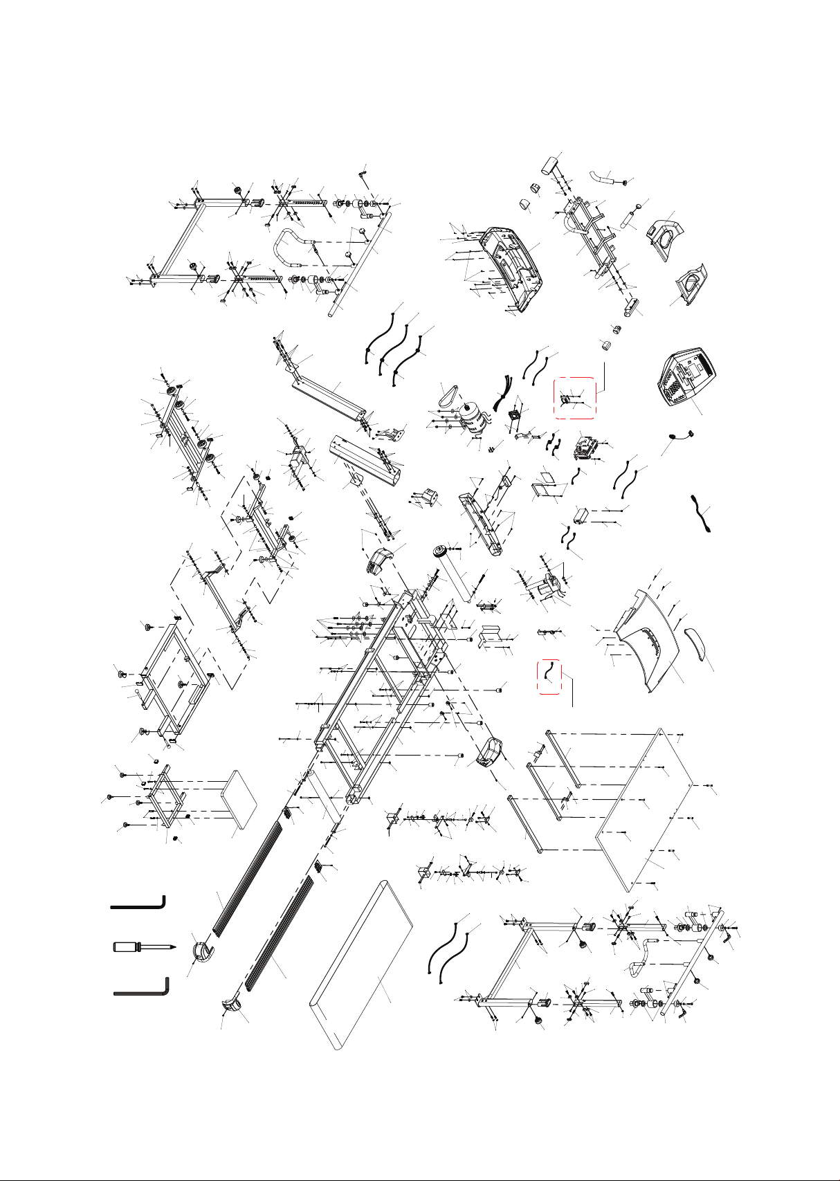
51
Exploded view drawing
31
30
10
36-15
5
36-17
36-16
27
112
112
17
17
43
44
16
33
32
13
12
6
7
6
14
14
15
15
15
15
148
147
136
138
231
77
77
73
73
73
65
65
65
65
65
65
131
131
18
19
20
21
104
58
59
3
4
140
140
11
35
34
108
108
1
52
52
53
236
236
236
53
53
52
77
78
78
77
77
77
77
77
59
58
58
153
59
117
117
117
117
117
77
117
110
110
178
204
204
208
204
204
179
180
181
280
54
55
134
55
56
73
74
193
265
73
73
276
45
45
37
37
73
73
279
183
183
187
187
189
189
189
189
190
192
192
183
183
188
188
191
195
197
197
196
196
196
196
196
196
196
196
196
196
196
24
24
24
24
205
205
205
205
38
38
38
38
42
42
42
42
57
148
148
147
147
26
26
63
63
63
63
63
63
63
63
54
59
54
59
59
54
54
59
54
54
54
54
54
54
54
54
54
55
55
55
55
55
55
55
55
55
55
55
55
55
55
55
55
55
55
55
55
55
55
56
56
56
56
56
56
58
58
58
58
62
62
59
59
59
59
64
64
64
64
64
64
64
64
2
151
152
59
78
78
78
78
78
132
132
132
132
77
66
67
68
68
71
72
73
73
73
73
73
73
104
61
61
61
61
61
61
60
60
60
60
60
60
62
62
62
62
62
62
62
62
212
212
212
212
213
213
66
66
66
66
198
198
198
198
199
199
200
200
60
203
203
203
203
206
206
206
206
214
214
214
214
214
214
207
207
207
216
216
216
216
217
217
218
218
218
218
218
218
218
218
221
221
51
51
231
41
134
223
223
224
224
224
226
226
226
153
227
227
228
228
228
228
40
40
40
40
230
230
231
222
77
148
139
36
153
73
125
73
125
125
73
281
62
62
153
58
58
59
58
59
134
119
119
119
119
119
119
119
73
125
153
59
153
59
153
59
59
153
226
216
216
182
182
224
185
224
185
184
184
184
184
216
212
212
224
224
186
186
186
186
185
185
268
271
274
212
212
258
257
258
256
256
261
256
257
258
258
261
256
261
258
258
257
256
256
216
216
261
256
258
216
216
257
258
256
216
216
62
263
73
119
119
73
213
213
213
213
254
254
250
247
74
74
252
249
260
248
253
211
251
210
245
244
243
255
218
218
255
218
218
244
244
243
209
209
286
286
243
244
253
248
252
249
74
246
210
211
251
245
244
243
74
247
250
260
260
60
60
9
8
77
77
77
77
240
240
201
201
201
201
204
275
29
41
41
246
204
32
32
32
32
231
50
302
231
262
262
39
39
119
73
73
119
290
291
73
119
292
295
296
73
119
293
220V使用
110V不使用
294
305
137 113 259
264
269
270
303
304
266
267
277
278
282
284
285
283
287
288
298
299
297
297
300
270
110V使用
220V不使用
L
o
re

52
7.0 T parts list
1
2
3
4
5
6
7
8
9
10
11
12
13
14
15
16
17
18
19
20
21
24
26
27
29
30
31
32
33
34
35
36
Main frame
Incline bracket
Console mast locking assembly ( l )
Console mast locking a Ssembly ( r )
Console support
Running deck stabilizer assembly(a)
Running deck stabilizer assembly(b)
Belt guide(r)
Belt guide(l)
Front roller w/pulley
Rear roller
Running deck
Running belt
Cushion a, Middle
Cushion b, front & rear
Drive motor belt, poly -V
1380m/m_aluminum foot rail
Aluminum upright (l)
Aluminum upright (r)
Upright xing plate(l)
Upright xing plate(r)
Ø82 × Ø14 × 35m/m_transportation wh Eel
Incline rubber foot
800m/m_safety key
Front motor cover
Motor top cover
Top motor cover plate
Motor base cap (r)
Motor base cap (l)
Foot rail cap (r)
Foot rail cap (l)
Console assembly
1
1
1
1
1
2
1
1
1
1
1
1
1
2
4
1
2
1
1
1
1
4
2
1
1
1
1
1
1
1
1
1
Item Description Qty

53
72
73
74
76
77
78
104
108
110
112
113
117
119
125
131
132
134
136
137
138
139
140
147
148
151
152
153
178
179
180
181
182
2
31
6
4
23
8
6
6
2
2
1
10
15
4
2
4
5
1
1
1
1
4
5
9
1
1
18
1
1
1
1
2
M4 × P0.7 × 5.0t_nyloc nut
M5 × P0.8 × 12m/m_phillips head screw
M5 × P0.8 × 5.0t_nyloc nut
M3 × 12m/m_tapping screw
M5 × 12m/m_tapping screw
M5 × 15m/m_sheet metal screw
3/8" × Unc16 × 3-3/4"_button head socket bolt
M8 × P1.25 × 12m/m_socket head cap bolt
M5 × 10m/m_phillips head screw
M5 × 30m/m_phillips head screw
Phillips head Screw driver
Ø3.5× 12m/m_tapping screw
M5 × 1.5t_split washer
M5_star washer
M8 × p1.25 × 35m/m_at head countersink bolt
Ø3 × 8m/m_tapping screw
Ø10 × Ø24 × 3.0t_nylon washer
3/8" × Unc16 × 2"_socket hea D cap bolt
L allen wrench
3/8" × Unc16 × 2-1/4"_socket head cap bolt
Inverter mounting bracket
M3 × 10m/m_sheet metal screw
Ø10 × Ø14 ×14m/m_bushing
Ø13 × Ø35 × 5.0t_nylon washer
Left handgrip
Right hAndgrip
3/8" × Unc16 × 3/4" _button head socket bolt
Frame base
Folding assembly bracket
Incline bracket
Step up frame
Parallel bar frame
Item Description Qty

54
36-15
36-16
36-17
37
38
39
40
41
42
43
44
45
50
51
52
53
54
55
56
57
58
59
60
61
62
63
64
65
66
67
68
71
1
1
1
2
4
2
4
4
4
1
1
2
1
2
4
3
15
24
7
4
19
32
10
6
20
8
8
6
5
1
2
2
Console bottom cover
Console top cover(r)
Console top cover(l)
Oval tube end cap
25m/m × 50m/m_square end cap
Hand pulse end cap
Stable wheel spacer
Ø10 × Ø25 × 0.8t_nylon washer
Motor cover anchor(d)
Rear adjustment base (r)
Rear adjustment base (l)
80m/m_handgrip foam
Ground isolation cap
3/8" × 3/4"_hex head bolt
M10 × P1.5 × 65m/m_hex head bolt
M10 × P1.5 × 50m/m_hex head bolt
Ø10 × 1.5t_split washer
Ø10 × Ø19 × 1.5t_at washer
M10 × P1.5 × 8.0t_nyloc nut
3/8" × Unc16 × 1-1/2"_socket head cap bolt
Ø3/8" × 2.0t_split washer
Ø3/8" × Ø25 × 2.0t_at washer
M8 × P1.25 × 45M/m_socket head cap bolt
Ø8× 1.5t_spl It washer
Ø8 × Ø16 × 1.0t_at washer
M8 × P1.25 × 110m/m_socket head cap bolt
M8 × P1.25 × 6.5t_square nut
M8 × P1.25 × 55m/m_at head countersink bolt
M10 × P1.5 × 40m/m_socket head cap bolt
M10 × P1.5 × 80m/m_socket Head cap bolt
M10 × P1.5 × 100m/m_socket head cap bolt
M4 × P0.7 × 35m/m_phillips head screw
Item Description Qty

55
Item Description Qty
183
184
185
186
187
188
189
190
191
192
193
195
196
197
198
199
200
201
202
203
204
205
206
207
208
209
210
211
212
213
214
216
4
4
4
4
2
2
4
1
1
2
1
1
14
2
4
2
2
4
4
4
6
4
4
4
1
2
2
2
16
8
8
16
P. Bar vertical adjustment tube
P. Bar bearing inner race
3/8" × Unc16 × 1-1/2" _button head socket bolt
M5 × 6m/m_socket head cap bolt
P. Bar horizontal adjustment arm (l)
P. Bar horizontal adjustment arm (r)
P.Bar horizontal adj. Cap
Parallel handle bar (l)
Parallel Handle bar (r)
P.Bar lift assist handle
Fan back plate
Fan mounting plate
Ø14 × Ø10 × 25m/m_podwer metallurgy sleeve
Ø20 × Ø13.4 × 41m/m_podwer metallurgy sleeve
M14 × 17m/m_seat/handlebar adj. Locking lever
Ø54 × 25m/m_transportation wheel
Ø60 × 15m/m_rubber foot
Ø37 × 3/8"_adjustment foot pad
Ø55 × 3/8"_adjustment foot pad
Plastic tube insert
30m/m × 30m/m_square end cap
30m/m × 60m/m_square end cap
Ø57 × m14_locking knob
3/8" × unc16 × 25m/m_brake tension knob
Step up platform
Step sensor mounting plate
Step magnet plate
Ø10 × 3t × N35_braking magnet
M8 × P1.25 × 25m/m_at head countersink bolt
M5 × P0.8 × 12m/m_at head socket screw
P. Bar bearing
Pu wheel

56
Item Description Qty
217
218
221
222
223
224
226
227
228
230
231
236
240
243
244
245
246
247
248
249
250
251
252
253
254
255
256
257
258
259
260
261
2
16
2
1
2
7
8
2
4
2
12
4
2
6
6
2
2
2
4
2
2
2
2
2
2
2
8
4
8
1
4
4
Step up frame pop pin
M4 × P0.7 × 8m/m_phillips head screw
5/16" × Unc18 × 5/8"_hex head bolt
3/8" × Unc16 × 1-1/2" _hex head bolt
3/8" × Unc16 × 3" _heX head bolt
3/8" × Unc16 × 7.0 t _nyloc nut
3/8" × Unc16 × 2" _button head socket bolt
1/2" × Unc13 × 2-1/4"_hex head bolt
Ø13 × Ø26 × 2.0t_at washer
1/2" × Unc20 × 8.0t_nyloc nut
Ø3/8" × Ø35 × 2.0t_at washer
3/8" × Unc16 ×1-3/4"_socket head cap bolt
Ø14 × Ø20 × 2.0t_at washer
M5 × 15m/m_socket head cap bolt
Ø5 × Ø12 × 1.0t_at washer
M6 × P1.0 × 5.0t_nut
M5 × 30m/m_socket head cap bolt
M5 × 35m/m_socket head Cap bolt
Ø15_c ring
U-Joint, step sensor
U-Joint mounting plate
Step magnet holder
Plunger, step sensor
Linear bearing, step sensor
Bushing, incline frame
Cover, step sensor assembly
Ø13.5 × 30m/m_spring
Brake pad, p. Bar slide - 1
M6 × 19m/m_nut
6mm allen wrench
M6 × 20m/m_button head socket bolt
Brake pad, p. Bar slide - 2

57
Item Description Qty
262
264
265
266
267
268
269
270
271
274
275
276
277
278
279
280
281
282
283
284
285
286
287
288
290
291
292
293
294
295
296
297
2
1
1
1
1
1
1
2
1
1
1
1
1
1
1
1
1
1
1
1
1
2
1
1
1
1
1
1
1
2
2
2
Eva foam for rail strap
Power cord
A.C. Input module
200m/M_connecting wire (white)
200m/m_connecting wire (black)
A.C. Power lter
150m/m_connecting wire (white)
150m/m_connecting wire (black)
Lower control board
Inverter, a.C. Motor
Encoder, a.C. Motor
Fan, motor cooling
500m/m_motor fan connecting cable (black)
500m/m_motor fan connecting cable (white)
Drive motor
Front incline motor
Rear incline motor
Inverter signal cable, 2100m/m
Inverter to lcb cable, 800m/m
Rear incline cable, 2100m/m
Rs -485 communication cable
Step sensor board
Step sensor cable, right
Step sensor cable, left
Back plate
Plate
Breaker
Grounding brush
Brush holder
M3 × 10l_phillips head screw
M3 × 2.5t_luck nut
Ferrite core (29m/m)

58
Item Description Qty
298
299
300
302
303
304
305
1
1
1
2
1
1
1
Ferrite core(21.4m/m)
Ferrite core(30m/m)
80m/m_connecting cable of motor
Ø16 × Ø35 × 1t_at washer
300m/m_connecting wire (white)
300m/m_connecting wire (black)
Ø5.2 × 0.4t × 14.5l_constrict spring
59
• Belt and deck
Your treadmill uses a very high-ecient low-friction deck and belt.
Performance is maximized when the bed is kept as clean as
possible. Use a soft, damp cloth or paper towel to wipe the edge
of the belt and the area between the belt edge and frame. Also
reach as far as practical directly under the belt edge. This should
be done once a month to extend belt and deck life. Use water only
no cleaners or abrasives. A mild soap and water solution along
with a nylon scrub brush will clean the top of the textured belt.
Allow the belt to dry before using.
• General cleaning
Dirt, dust, and carpet bers can block air inlets and accumulate on
the running belt. On a monthly basis: vacuum underneath your
treadmill to prevent buildup. Once a year, you should remove the
motor hood and vacuum out dirt that may accumulate. Unplug
power cord before this task.
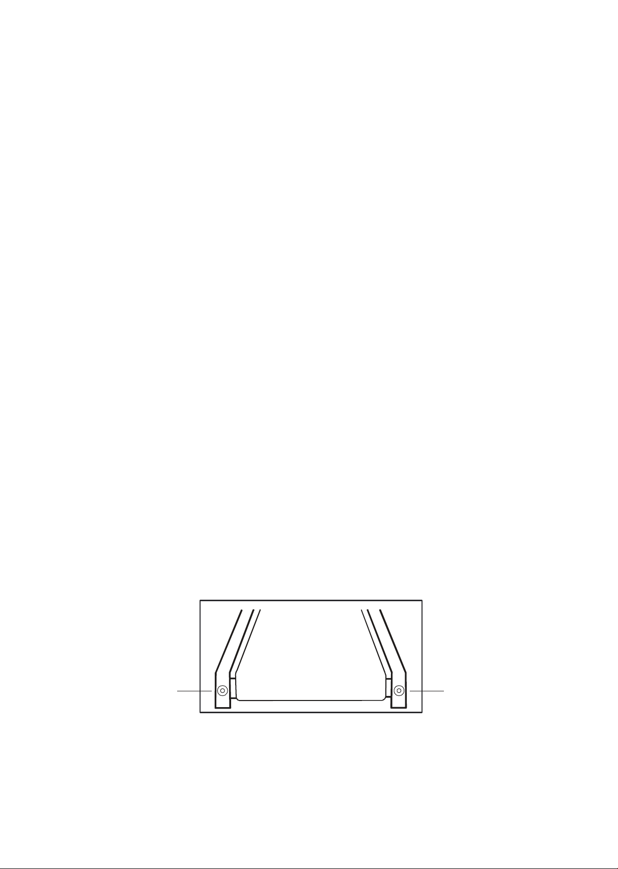
Belt adjustments
• Tread-belt tension adjustment
Adjustment must be made from the rear roller. The adjustment bolts
are located at the end of the step rails in the end caps, as noted in
diagram below.
Note: Adjustment is through small hole in the end cap.
Tracking /
Tension
Adjustment
Tracking /
Tension
Adjustment
Maintenance

60
Tighten the rear roller bolts only enough to prevent slippage at the
front roller. Turn both tread-belt tension adjustment bolts with a
10mm allen wrench in increments of 1/4 to 1/2 turn each and inspect
for proper tension by walking on the belt at a low speed, making sure
the belt does not slip. Keep tensioning the bolts until the belt stops
slipping.
• If you feel the belt is tight enough, but it still slips, the problem may be
a loose Motor drive belt under the front motor cover.
Do not overtighten
Over tightening will cause belt damage and premature bearing
failure.
Treadbelt tracking adjustment
The performance of your treadmill is dependent on the frame running
on a reasonably level surface. If the frame is not level, the front and
back roller cannot run parallel, and constant belt adjustment may be
necessary.
The treadmill is designed to keep the tread-belt reasonably centered
while in use. It is normal for some belts to drift near one side while
the belt is running with no one on it. After a few minutes of use, the
tread-belt should have a tendency to center itself. If, during use, the
belt continues to move toward one side, adjustments are necessary.
To set treadbelt tracking
Use a 10mm Allen wrench to adjust the rear roller. Make tracking
adjustments from the left side only. Set belt speed at approximately 2
to 3 mph.

61
Remember, a small adjustment can make a dramatic dierence!
Turn the bolt clockwise to move the belt to the right. Turn the bolt
only a 1/4 turn and wait a few minutes for the belt to adjust itself.
Continue to make 1/4 rotation turns until the belt stabilizes in the
center of the running deck.
The belt may require periodic tracking adjustment depending on use
and walking/ running characteristics. Some users will aect tracking
dierently. Expect to make adjustments as required to center the
tread-belt. Adjustments will become less of a maintenance concern
as the belt is used. Proper belt tracking is an owner responsibility
common with all treadmills.
Attention
Damage to the running belt resulting from improper tracking /
tension adjustments is not covered under the warranty.
Maintenance menu in console software
The console has built in maintenance/diagnostic software. The soft-
ware will allow you to change the console settings from English to
Metric and turn o the beeping of the speaker when a key is pressed
for example. To enter the maintenance menu (may be called Engi-
neering mode, depending on version) press and hold down the Start,
Stop and Enter keys. Keep holding the keys down for about 5 seconds
and the message window will display “Maintenance mode”. Press the
enter button to access the menu below:
Maintenance mode
• Press and hold the start, stop and enter key at the same time, until the
display shows “Maintenance mode”. Press the enter key. You can now
scroll through the menu using the up and down keys. Use the stop key
to return to previous menu selection. The menu selections are:

62
• Key test
- Press each key to verify it is functioning correctly
• Display test
- Lights all LED lights
• Functions
- Sleep
Turns sleep mode on or o. When o, display power is always on.
- Pause
Turns pause mode on or o. When on, pause lasts 30 minutes.
- Odometer reset
Reset odometer readings
- Units
Set display to english or metric readings
- Grade return (GS Mode)
Turns GS mode on or o. Returns the elevation to lowest setting
when pause is pressed
- Beep
Turns the speaker (beep sound) on or o.
- Service mode:
Incline
- MW scrolls: “Use incline keys for front use speed keys for rear” then
switch to VR display below.
- Incline keys operate front motor, speed keys operate rear motor.
Hold down up/down key to operate motor, stop when key is released.
Motor is allowed to move until limit switch activated.
- MW displays A/D values for both position sensors. Example of the
readings F920 R 70. F=Front incline sensor and R = Rear incline
sensor. The readings will be opposite: when at lowest incline the front
will show a large number and rear will be small.
- Drive Motor
MW displays: “Use speed keys to move motor”. Each key press
increases motor speed 0.1 mph/kph
MW then shows: RPM 000 AMP 00.0. The sensor reading
indicates motor RPM, not belt speed. The AMP is measuring motor
current
1
2

63
- Motor brake: Brake on (brake coil turned o) (User press enter to
turn brake o)
- Step sensors
Test
Use sensor outputs to light DM similar to Symmetry display. This
test is only to make sure the sensors are functioning and does
not test accuracy. The DM graph shows left and right sensor
activity when stepping on the deck. Both sides of the graph will
light at the same time, but the side the user steps with would
show more segments lit.
Calibration
- MW: START LEFT SIDE
- When Start is pressed the MW shows: AD _ _ _ TGT 65
- Speaker will beep slowly when magnet distance is too far,
quickly when near and steady when correct.
- Press enter to continue
- MW: START RIGHT SIDE
- When Start is pressed the MW shows: AD _ _ _ TGT 65
- Speaker will beep slowly when magnet distance is too far,
quickly when near and steady when correct.
- User press enter or stop to end calibration
• Acceleration key lock
- MW show “accel key”, press enter then MW shows “accel
locked”. This is the default. If the user presses the up or down key
the MW shows “accel unlocked”. Press enter to exit.
• Speed limit setting
- MW shows “speed limit”, press enter. The MW shows limit 10.0
mph. This is the default setting and is the top forward speed of the
treadmill.
- If the user presses the down key the MW shows Limit 9.9 mph.
The top limit can be changed in 0.1 mph increments.
- The minimum speed limit setting is 3.0 mph.
• Security
- MW show “security” MW shows “child lock on ” or o , Sets
the child lock function. This function locks out the keypad until a
pre-determined key sequence is pressed. Key sequence = start &
enter held down together until unlocked.
1
2

64
Factory and acceleration settings
Enter the Factory settings; press Start and Speed Fast keys while
console is in a.power up reset. User presses enter
• Units: English
- The default setting is English. User can press any up/down arrows
to change to Metric. User presses enter.
• Adjust min speed then press enter
- Default value is 0.1 mph and can be adjusted up to 0.5 mph. The
speed number to be shown in the speed window.
• Adjust max speed then press enter
- Default value is 10.0 mph and can be adjusted down to 3.0 mph.
The speed number to be shown in the speed window
• Adjust reverse speed max then press enter
- Default value is 3.0 mph and can be adjusted down to 1.0 mph and up
to 5.0 mph.
• Adjust belt speed acceleration time per each 1.0 mph
- The default is 0:03 seconds and will be shown in the Time window.
The time can be adjusted down to 0:01 and up to 1:00 minute
• Adjust belt speed deceleration time per each 1.0 mph
- The default is 0:03 seconds and will be shown in the Time window.
The time can be adjusted down to 0:01 and up to 1:00 minute
• Press enter for grade calibration or to exit hold stop key until
reset.
• Adjust max incline then press enter
- The default value is 15 and can be adjusted down to 10
• Adjust max decline then press start to calibrate
- The default value is 5 and can be adjusted up to 10
• If Grade calibration is successful the MW shows “passed” for 3
seconds then exit to idle mode.

65
Error codes, messages and solution/cause
E1 Over Current
Deck Lube
Bad Drive or Motor
Check Brake
E2 Over Volt
Check AC line V
E3 Over V Decel
Check AC line V
Check Brake
E4 Ground Fault
Check wiring
Replace Drive
E5 IGBT Fault
Check wiring
Replace Drive
E6 Drive Ovrload
Deck Lube
Brake locked
Bad Drive
Bad Motor
E7 Thrm Ovrload
Brake locked
Deck Lube
Bad Drive
Bad Motor
E8 Over Torque
Brake locked
Deck Lube
Bad Drive
Bad Motor
E9 Over I Speed
Check Brake
Deck Lube
Bad Drive
Bad Motor
E10 Over I Accel
Deck Lube
Bad Drive
Bad Motor
E11 Over I Decel
Deck Lube
Bad Drive
Bad Motor
E12 EPROM RD
Check AC Line V
Reset Power
Bad Drive
E13 EPROM WR
Check AC Line V
Reset Power
Bad Drive
E14 Ext Fault
Reset Power
E15 U Phase I
Reset Power
Bad Drive
E16 W Phase I
Reset Power
Bad Drive
E17 HW Fault
Reset Power
Bad Drive
E18 IGBT O-Heat
Bad Drive Fan
Dirty Heat Sink
E19 Ambient Temp
Air Vent Blocked
Bad Fan
E20 Inrush Fault
Reset Power
Bad Drive
E21 In Sig Lost
Check Wiring
Bad Drive

66
E22 RS-485 Flt
Check Wiring
E23 PID Error
Check Wiring
Chk Para Setting
E24 PU Comm
Bad Drive
E25 Auto Tune
Chk Motor wires
Reset Power
E26 Bk Chopper
Reset Power
Bad Drive
E27 PG Error
Check Motor
E28 Phase Loss
Check Wiring
Bad Drive
E29 I Signl Stop
Reset Power
Bad Drive
E30 CPU Error
Electronic circuit
fault
E31 Fan
Drive Fan Bad
E32 Analog In
Check Wiring
Bad Drive
E33 Over Trque
Mechanical
Deck Lube
Brake
Bad Motor
Bad Drive
E34 Thrm Ovrld 2
Brake locked
Deck Lube
Bad Drive
Bad Motor
E35
Motor Sel
Motor Wiring
E36 LV Bus Run
Check AC Line V
Bad Drive
E37 LV Bus
Check AC Line V
Bad Drive
E38 Ext BB
Para Settings
E41 Incline Err
E42 Decline Err

67
Patient weight capacity
440 Lbs. (200 Kgs.)
Power
115 Volts A.C., 20 Amps, 60 Hz.
Fuse rating
Circuit breaker: AC 125V, 20A
Mode of tripping: Thermal
Operating speed: 0.25~3.0 sec.
Breaking capacity: 1000A, 125 VAC
Incline
Front: 0 to 15% grade
Rear: 0 to 10% grade
7.0 T
Set-up dimensions
Length : 94” (239 cm) with rear step.
Width : 36” (91.4 cm)
Height : 56.5” (143.5cm)
Product weight
514.8 Lbs. (234 Kgs)
Fuse on inverter
Voltage: 125 Vac
Current: 1A
Operating Speed: 0.4~1.0 sec.
Breaking Capacity: 50A, 125 Vac
Size: 2.65mm X 7.1mm
Speed
Forward : 0.0 to 10.0 mph (0.0 to 16 kph)
Reverse : 0.0 to 3.0 mph (0.0 to 5 kph)
Readouts
Time, Grade, Distance, Speed, Pause, METS, Calories, Pace,
Cadence, Left and Right Step Length, Symmetry Index
Disposal
Reference should be made to local regulations concerning the disposal
of this product at the end of useful life.
Specications

68
Certications
TUV listed to ANSI/AAMI ES60601-1:2005+A2 (R2012) +A1,
CAN/CSA-C22.2 No. 60601-1:14,
CE conformity to EN 60601-1 EMC, Compliance to EN 60601-1-2
Classication
Class I measuring, Type B, ordinary equipment, continuous operation.
This product is classed as ordinary equipment according to
IEC/EN/UL60601-1 and is not protected against the ingress of water.
Manufacturer
69
Guidance and manufacturer’s declaration -
electromagnetic compatibility
The 7.0 T is intended for use in the electromagnetic environment specied below. The customer or
the user of the 7.0 T should assure that it is used in such an environment.
Emissions test
Compliance
Electromagnetic environment –
guidance
RF emissions
CISPR 11
Group 1
The 7.0 T uses RF energy only for
its internal function. Therefore, its RF
emissions are very low and are not
likely to cause any interference in
nearby electronic equipment.
RF emissions
CISPR 11
Class B
The 7.0 T is suitable for use in all
establishments, including domestic
establishments
Immunity test
IEC 60601
test level
Compliance level
Electromagnetic environment
–
guidance
Electrostatic
discharge (ESD)
IEC 61000-4-2
6 kV contact
8 kV air
6 kV contact
8 kV air
Floors should be wood, concrete or
ceramic tile. If oors are covered with
synthetic material, the relative
humidity should be at least 30 %.
Power frequency
(50/60 Hz)
magnetic eld
IEC 61000-4-8
3 A/m
3 A/m
Power frequency magnetic elds
should be at levels characteristic of a
typical location in a typical
commercial or hospital environment.
Radiated RF
IEC 61000-4-3
3 V/m
80 MHz to 2,5 GHz
3 V/m
d = 1,2 80 MHz to 800 MHz
d = 2,3 800 MHz to 2,5 GHz
Where P is the maximum output
power rating of the transmitter in
watts (W) according to the transmitter
manufacturer and d is the
recommended separation distance in
meters (m).
Field strengths from xed RF
transmitters, as determined by an
electromagnetic site survey, a) should
be less than the compliance level in
each frequency range. B) Interference
may occur in the vicinity of equipment
marked with the following symbol:
Recommended separation distances between
portable and mobile RF communications equipment and the 7.0 T
The 7.0 T is intended for use in an electromagnetic environment in which radiated RF disturbances
are controlled. The customer or the user of the 7.0 T can help prevent electromagnetic interference by
maintaining a minimum distance between portable and mobile RF communications equipment
(transmitters) and the 7.0 T as recommended below, according to the maximum output power of the
communications equipment.
Rated maximum
output power of
transmitter
W
Separation distance according to frequency of transmitter
m
150 kHz to 80 MHz
d =
1,2
80 MHz to 800
MHz
d =
1,2
800 MHz to 2,5 GHz
d =
2,3
0,01
0,12
0,12
0,23

70
Immunity test
IEC 60601
test level
Compliance level
Electromagnetic environment
–
guidance
Electrical fast
transient/burst
IEC 61000-4-4
+/-2 kV for power
supply lines
+/-1 kV for
input/output lines
+/-2 kV for power
supply lines
+/-1 kV for
input/output lines
Mains power quality should be that
of a typical commercial or hospital
environment.
!
!
!
!
Note
• If the device is interfered by power or signal cable, image quality
may be reduced or abnormally displayed. Such kind of interference
images could be easily identied and dierentiated from the physi-
ological characteristics of patient and longer clinical time consumed
but wouldn’t have any diagnostic accuracy issue.
• If there is a certain frequency of image interference, there is a need
of isolation or ltering of the RF signal.

71
Package contains fragile electronic equipment.
Care should be used when handling.
The product inside the packaging could be easily
damaged if dropped or handled without care and
attention. The contents are fragile!
Do not use forklift truck here.
Do not use Spade truck here.
Do not use Razorback truck here.
Hand truck only.
Description
of packaging
symbols
Indicates that the package is heavy and two or more
people are required to lift.
Warning
Warning

72
Indicates that an object is capable of being recycled
- not that the object has been recycled or will be
accepted in all recycling collection systems.
Top. This side up.

73
Warranty
commercial
Frame
Lifetime
Drive motor
10 years
Parts
3 years
Labor
3 years
Wear items
6 months
EMS brake
5 years
Product warranty
Dyaco Commercial & Medical North America LLC (hereinafter
“Dyaco”), the manufacturer of the Philips Professional Series Physical
Therapy Products (hereinafter “Products”) warrants all of the Prod-
ucts and their components listed below for the periods of time set
out on this page below from the date of sale, as determined by sale
receipt, or in the absence of a sales receipt, eighteen (18) months
from the original factory shipping date. During the applicable war-
ranty periods, Dyaco’s responsibilities under these warranties include
providing, at no charge, new or remanufactured parts, as determined
by Dyaco at its sole and absolute discretion, and covering the cost of
labor deemed necessary by Dyaco, at its sole and absolute discretion,
to remedy faults giving rise to applicable warranty claims. The war-
ranty periods set out below are subject to the performance of proper
care and maintenance, as set out in this user manual, by the original
purchaser of the equipment. Warranties are not transferable.
* Wear items are rubber hand grips, pedals, console overlay and drive belt
Normal responsibilities of the facility
The facility is responsible for the items listed below
• The warranty registration must be completed online to validate the
manufacturer’s limited warranty.
• Proper use of the tness equipment in accordance with the instruc-
tions provided in this manual.
• Proper installation in accordance with instructions provided with
the tness equipment and with all local electric codes.

74
• Proper connection to a grounded power supply of sucient voltage,
replacement of blown fuses, repair of loose connections or defects
in house or facility wiring.
• Expenses for making the tness equipment accessible for servicing,
including any item that was not part of the tness equipment at the
time it was shipped from the factory.
• Damages to the tness equipment nish during shipping,
installation or following installation.
• Routine maintenance of this unit as specied in this manual.
Exclusions
This warranty does not cover the following:
• Consequential, collateral, or incidental damages such as property
damage and incidental expenses resulting from any breach of this
written or any implied warranty. Note: Some states do not allow the
exclusion or limitation of incidental or consequential damages, so
this limitation or exclusion may not apply to you.
• Service call reimbursement to the consumer. Service call
reimbursement to the dealer that does not involve malfunction or
defects in workmanship or material, for units that are beyond the
warranty period, for units that are beyond the service call
reimbursement period, or units not requiring component
replacement.
• Damages caused by services performed by persons other than
authorized Dyaco service companies, use of parts other than
original Dyaco parts, or external causes such as alterations,
modications, abuse, misuse, accident, improper maintenance,
inadequate power supply.
• Products with original serial numbers that have been removed or
altered.
• Products that have been; sold, transferred, bartered, or given to a
third party.
• Products that are used as store display models.
• Products that do not have a warranty registration on le at Dyaco.
Dyaco reserves the right to request proof of purchase if no warranty
record exists for the product.

75
• Manufacturer, distributor, or the Licensor shall not be responsible or
liable of any direct, indirect, general, special, punitive, incidental or
consequential damages; loss of or damage to property; claims of
third parties; loss of life; personal injury (including further injury, or
re-injury), and any other losses or damages of any kind or character,
arising out of or in connection with the use of Biophysical Agents by
the facilities or clinicians. The facilities or clinicians that select,
prescribe, and implement the use of Biophysical Agents will assume
the related responsibility.
• Denitions of “ Biophysical agents ” : Biophysical agents are a broad
group of agents that use various forms of energy and are intended
to assist muscle force generation and contraction; decrease
unwanted muscular activity; maintain strength after injury or sur-
gery; modulate or decrease pain; reduce or eliminate edema;
improve circulation; decrease inammation, connective tissue
extensibility, or restriction associated with musculoskeletal injury or
circulatory dysfunction; increase joint mobility, muscle performance,
and neuromuscular performance.
• Physical therapists select, prescribe, and implement the use of
biophysical agents when the examination ndings, diagnosis, and
prognosis indicate the use of these agents to reduce risk factors
and complications; enhance health, wellness, or tness; enhance or
maintain physical performance; or prevent or remediate impair-
ments in body functions and structures, activity limitations, or par-
ticipation restrictions. The use of biophysical agents in the absence
of other interventions should not be considered to be physical ther-
apy unless there is documentation that justies the necessity of
their exclusive use.
• Use of the products in any way other than described within
products’ operation manual, either intentionally or by error.
• Damages due to improper storage or transport or other causes not
solely attributable to Manufacturer.
• The exact amount of indemnication or cost arising out of breach of
this written or any implied warranty shall be fairly negotiated by
both you and Manufacturer.
• This warranty is expressly in lieu of all other warranties expressed or
implied, including the warranties of merchantability and/or tness
for a particular purpose.

76
Service
Keep your bill of sale. Twenty four (24) months from the date on the
bill of sale or eighteen (18) months from the date of factory shipping
as determined by the serial number establishes the warranty period
should service be required. If service is performed, it is in your best
interest to obtain and keep all receipts. This written warranty gives
you specic legal rights. You may also have other rights that vary from
state to state. Service under this warranty must be obtained by fol-
lowing these steps, in order:
• Contact your selling authorized Dyaco dealer. OR
• Contact your local authorized Dyaco service organization.
• If there is a question as to where to obtain service, contact our
service department at 1-866-869-4409.
• Dyaco’s obligation under this warranty is limited to repairing or
replacing, at Dyaco’s option, the product through one of our
authorized service centers. All repairs must be preauthorized by
Dyaco. If the product is shipped to a service center freight charges
to and from the service center will be the customer’s responsibility.
For replacement parts shipped while the product is under warranty,
the customer will be responsible for shipping and handling charges.
• The owner is responsible for adequate packaging upon return to
Dyaco. Dyaco is not responsible for damages in shipping. Make all
freight damage claims with the appropriate freight carrier. Do not
ship any unit to our factory without a return authorization number.
All units arriving without a return authorization number will be
refused.
• For any further information, or to contact our service department by
email, or phone call, and also please refer to website for additional
information:
- Consumer care service email address: [email protected]om
- Consumer care service phone number: 1-886-869-4409
Product features or specications as described or illustrated are
subject to change without notice. All warranties are made by
Dyaco Commercial & Medical North America LLC. This warranty
applies only in the 48 contiguous United States.
Note: This warranty does not apply to Alaska or Hawaii.

2019© Dyaco Commercial & Medical North America LLC. All right reserved.
The Philips trademark and the Philips Shield Emblem are registered trademarks of Koninklijke Philips N.V. used under license.
This product has been manufactured by and is sold under the responsibility of Dyaco Commercial & Medical North America LLC,
and Dyaco Commercial & Mediacl North America LLC is the warrantor in relation to this product.