Loading ...
Loading ...
Loading ...
5
List of Materials
Removing the packaging
CAUTION!
Remove carton carefully, wear gloves to protect against sharp edges.
WARNING!
Remove the protective lm covering the product before putting into
operation.
Parts supplied
• Downdraft assembly with blower already installed
• Metal grease lters
• 2 - Lower support legs
• 2 - End caps
• 6” round air transition
• 3
1
⁄4”x10” rectangular air transition
• Metalic top trim
• Control assembly
• Hardware bag with:
• Use, care and installation guide
• Plastic control base
• 1 - Shrinkable wire tube
• 2 - Plastic wire ties
• 2 - Installation brackets
• 4 - Plastic clips for aspiration plate
• 7 - Adhesive wire clips
• 8 - 4 x 8 mm mounting screws
• 11 - 4.5 x 13 mm mounting screws
• 3 - 3.5 x 9.5 mm transition mounting screws
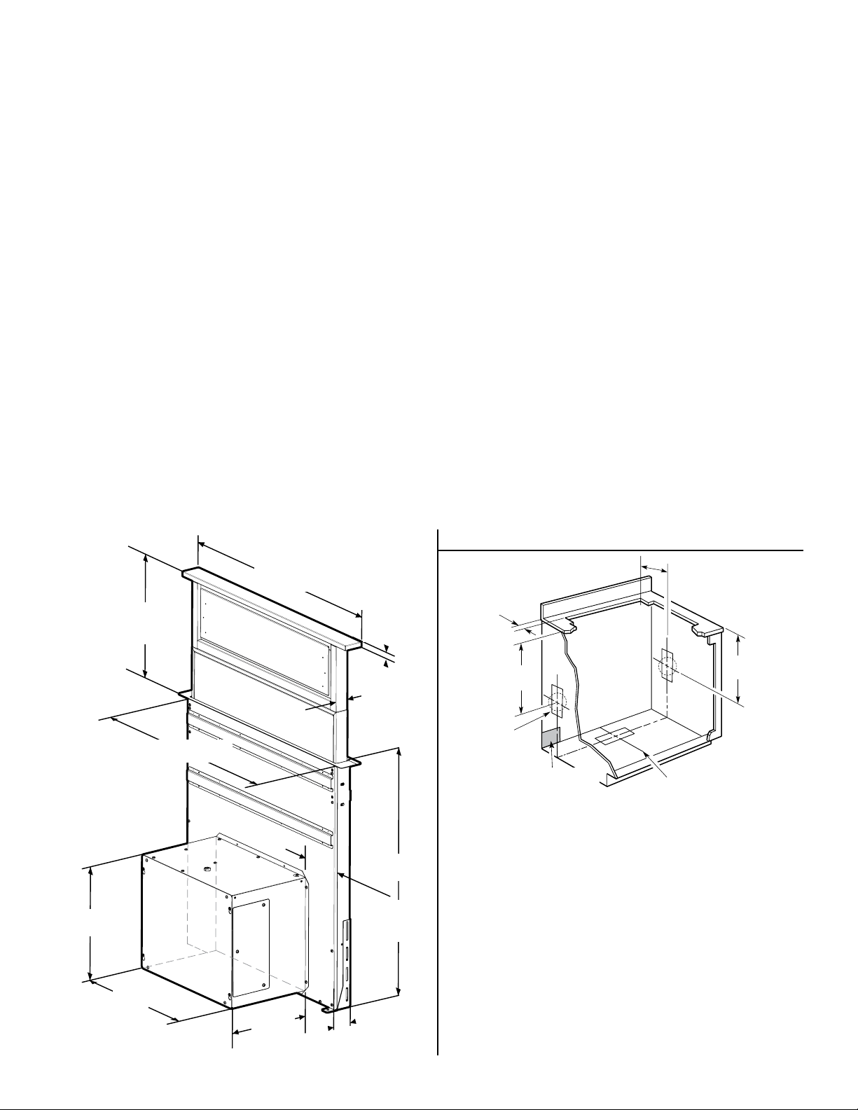
Product Dimensions
Parts needed
• Home power supply cable
• ½” (12.7 mm) UL listed or CSA approved strain relief
• 3 UL listed wire connectors
• 1 wall or roof cap
• 6” round metal vent system or 3
1
⁄4”x10” rectangular vent system
Tools/Materials required
• Level
• Drill with 1¼” (3.2 cm),⅛” (3.2 mm), and
5
⁄16” (7.9 mm)
drill bits
• Pencil
• Wire stripper or utility knife
• Tape measure or ruler
• Pliers
• Caulking gun and weatherproof caulking compound
• Vent clamps
• Jigsaw or keyhole saw
• Flat-blade screwdriver
• Metal snips
Top trim widths:
30” (76.2 cm)
36” (91.4 cm)
13
1
⁄2” (34.3 cm)
retractable
vent height
27” (68.6 cm) for 30” model
33” (83.8 cm) for 36” model
1
1
⁄2”
(3.8 cm)
28
1
⁄2”
(72.6 cm)
13
1
⁄8”
(33.4 cm)
16
1
⁄2”
(42 cm)
10”
(25.4 cm)
2
1
⁄8”
(5.4 cm)
5
1
⁄4” (13.3 cm)
for 30” models
8
1
⁄4” (21 cm)
for 36” models
19
⁄32”
(1.5 cm)
Cabinet Dimensions
9
1
⁄2”
(24.4 cm)
1
⁄2” (1.27 cm)
minimum
Centerline of
cooktop cutout
Locate power supply
junction box at lower
left hand rear corner
of the cabinet.
Cutouts are
for 3
1
⁄4” x 10”
(8.3 x 25.4 cm)
rectangular or 6”
(15.2 cm) round
vent system.
21
5
⁄16”
(54.1 cm)
21
5
⁄16”
(54.1 cm)
NOTES:
• See cooktop manufacturer’s instructions for cooktop cutout
depth and width.
• Use dimensions for vent system cutout location that applies to
your installation.
• Interior mounted blower systems connect with 3
1
⁄4” x 10”
(8.3 x 25.4 cm) rectangular or 6” (15.2 cm) round vent system.
The cutout locations for this vent system will depend on your
specic installation.
Loading ...
Loading ...
Loading ...