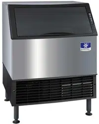
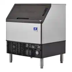
Installation, Operation and Maintenance Manual UnderCounter Ice Machines
Installation
Location of Ice Machine
The location selected for the ice machine must meet the following criteria. If any of these criteria are not met, select another location.
- The location must be indoors.
- The location must be free of airborne and other contaminants.
- The air temperature must be at least 40°F (4°C), but must not exceed 110°F (43°C).
- The location must not be near heat-generating equipment or in direct sunlight.
- The location must be capable of supporting the weight of the ice machine and a full bin of ice.
- The location must allow enough clearance for water, drain and electrical connections in the rear of the ice machine.
- The location must not obstruct airflow through or around the ice machine (condenser airflow is in and out the front). Refer to the chart below for clearance requirements.
- The location must not be near garbage or other contaminants.
- The ice machine must use legs or be sealed to the floor. Before sealing to the floor, the rubber bumpers on the bottom of the ice machine must be removed.

The ice machine may be built into a cabinet. There is no minimum clearance requirement for the top or left and right sides of the ice machine. The listed values are recommended for efficient operation and servicing only.
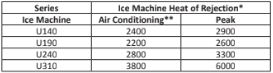
* B.T.U./Hour
** Because the heat of rejection varies during the ice making cycle, the figure shown is an average. Ice machines, like other refrigeration equipment, reject heat through the condenser. It is helpful to know the amount of heat rejected by the ice machine when sizing air conditioning equipment where self-contained air-cooled ice machines are installed.
LEVELING THE ICE MACHINE
- Screw the leveling legs onto the bottom of the ice machine.
- Screw the foot of each leg in as far as possible.
- Move the ice machine into its final position.
- Level the ice machine by using a level on top of the ice machine. Turn each foot as necessary to level the ice machine from front to back and side to side.
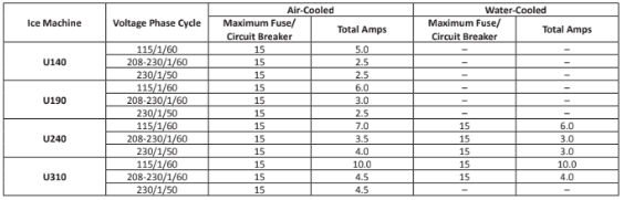
ELECTRICAL SPECIFICATIONS
WATER SUPPLY
Local water conditions may require treatment of the water to inhibit scale formation, filter sediment, remove chlorine, and improve taste and clarity.
WATER INLET LINES
Follow these guidelines to install water inlet lines:
- Do not connect the ice machine to a hot water supply.
- Be sure all hot water restrictors installed for other equipment are working. (Check valves on sink faucets, dishwashers, etc.)
- If water pressure exceeds the maximum (80 psig- 551.5 kPa) recommended pressure, obtain a water pressure regulator from your Manitowoc distributor.
- Install a water shut-off valve and union for both the ice- making and condenser water lines.
- Insulate water inlet lines to prevent condensation.
INSTALLATION NOTE (SWITZERLAND)
The connection to the drinking water network must be made with a certified backflow preventer type EA (EN13959) and with a certified connection hose (EN13618 or EN61770) on site.
DRAIN CONNECTIONS
Follow these guidelines when installing drain lines to prevent drain water from flowing back into the ice machine and storage bin:
- Drain lines must have a 1.5 inch drop per 5 feet of run (2.5 cm per meter) and must not create traps.
- The floor drain must be large enough to accommodate drainage from all drains.
- Run separate bin and water-cooled condenser drain lines.
- Insulate them to prevent condensation.
- Vent the ice machine drain. Do not vent the condenser drain on water-cooled models.
COOLING TOWER APPLICATIONS (Water-Cooled Models)
A water cooling tower installation does not require modification of the ice machine. The water regulator valve for the condenser continues to control the refrigeration discharge pressure.
It is necessary to know the amount of heat rejection and the pressure drop through the condenser and water valves (inlet and outlet) when using a cooling tower on an ice machine.
- Water entering the condenser must not exceed 90°F (32°C).
- Water flow through the condenser must not exceed 5 gallons (19 liters) per minute.
- Allow for a pressure drop of 7 psi (48 kPa) between the condenser water inlet and the outlet of the ice machine.
- Water exiting the condenser must not exceed 110°F (43°C).
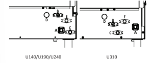
WATER SUPPLY & DRAIN LINE SIZING CONNECTIONS

Water/Drain Connections
A. Potable Water Inlet
B. Potable Water Outlet
C. Bin Drain
D. Condenser Water Inlet - (Water-cooled Only)
E. Condenser Water Outlet - (Water-cooled Only)
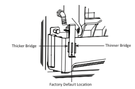
Ice Thickness Adjustment
The ice thickness can be adjusted to three levels.
- Pull forward on the bottom of the bracket until clear of the tab.
- Slide the bracket over the desired tab and release.
- The center position is the normal factory setting.
- To increase bridge thickness, raise the water level.
- To decrease bridge thickness, lower the water level.

Before Starting the Ice Machine
All Manitowoc ice machines are factory-operated and, normally, new installations do not require any adjustment.
Starting the ice machine and completing the Operational Checks are the responsibilities of the owner and operator.
Adjustments and maintenance procedures outlined in this manual are not covered by the warranty.
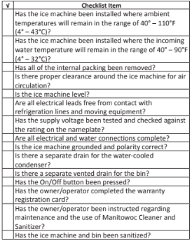
INSTALLATION CHECKLIST
Operation
Touch Pad Features
The touch pad offers a series of pressure sensitive buttons to control ice machine operation and provide operational status.
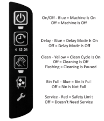
ON/OFF
- The On/Off Button is used to start and stop ice making. The blue light indicates whether the ice machine is Ice Making (light on) or Off (light off).
- NOTE: If ice is on the evaporator (during the freeze or harvest cycle) and the On/Off button is pressed, the next cycle will have a thick slab of ice. Press the On/Off button and allow the ice to melt off the evaporator, then start a new freeze cycle.
DELAY
Pressing the Delay button will start a delay period. The ice machine will finish the freeze and harvest cycle and then start the delay period.
- Pressing the button once will start a 4 hour delay period.
- Pressing the button twice will start a 12 hour delay period.
- Pressing the button three times will start a 24 hour delay period.
- Pressing the button four times will cancel the delay periods.
NOTE: The delay period will be canceled if power is interrupted to the ice machine. When power is restored, the ice machine will remain Off.
CLEAN
Pressing the Clean button for 3 seconds with the machine off will start a clean cycle. After the clean cycle is complete, the ice machine will automatically start an ice making cycle.
- Pressing the Clean button again within 45 seconds of the clean cycle starting will abort the clean cycle.
- Pressing the On/Off button anytime during the clean cycle will de-energize the On/Off LED and the ice machine will stop after the clean cycle is complete.
- Pressing the Clean button will pause the clean cycle. The On/Off and Clean lights will flash on/off to indicate pause mode. Pressing the Clean button again will continue the clean cycle from the point of interruption.
NOTE: Opening the ice damper for 30 seconds will cancel the clean cycle.
BIN FULL
- The Bin Full light energizes when the bin is full or is de- energized if the bin is not full.
SERVICE
- The Service light indicates the machine needs attention.
- Refer to Section 5 for more information if this light is energized.
Ice Making Sequence of Operation
NOTE: The On/Off button must be depressed and the ice damper must be closed before the ice machine will start.
Water Purge Cycle
The ice machine purges any remaining water from the water trough down the drain.
Freeze Cycle
Prechill - The refrigeration system chills the evaporator before water flow over the evaporator starts. The water inlet valve energizes during the pre-chill and remains on until the ice thickness float switch is satisfied.
Freeze - With water trough thermistor , the following sequence occurs in the freeze cycle:
- When the water temperature reaches 34°F, the water pump will de-energize for 25 seconds, then re-energizes.
- When the water pump restarts the water inlet solenoid energizes for 7 seconds.
- Water flowing across the evaporator will start to freeze and build ice on the evaporator. After a sheet of ice has formed, the harvest float switch signals the control board to start a harvest cycle.
Freeze - Without water trough thermistor , the following sequence occurs in the freeze cycle:
- At 3.75 minutes the water pump de-energizes for 25 seconds , then re-energizes.
- When the water pump restarts the water inlet solenoid energizes for 7 seconds.
- Water flowing across the evaporator will start to freeze and build ice on the evaporator. After a sheet of ice has formed, the harvest float switch signals the control board to start a harvest cycle.
Harvest Cycle
- Any remaining water is purged down the drain as refrigerant gas warms the evaporator. When the evaporator warms, the sheet of cubes slides off the evaporator and into the storage bin. If all cubes fall clear of the ice damper, the ice machine starts another freeze cycle.
Full Bin Cycle
- If the ice damper is held open by ice cubes, the ice machine shuts off. When the ice damper closes, the ice machine starts a new cycle at the water purge.
Control Board Timers
The control board has the following non-adjustable timers:
- The ice machine is locked into the freeze cycle for 6 minutes before a harvest cycle can be initiated.
- The maximum freeze time is 45 minutes, at which time the control board automatically initiates a harvest sequence.
- The maximum harvest time is 7 minutes. When harvest is complete the control board automatically initiates a freeze sequence.
- If the ice damper does not open and close within the 7 minute harvest cycle, the ice machine enters a water thaw cycle for 170 seconds. If the damper does not open and close within the 170 second thaw cycle, a second thaw cycle starts. The control board automatically initiates a freeze sequence when the thaw cycle(s) is complete.
SAFETY LIMITS
Safety limits are stored and indicated by the control board. The number of cycles required to stop the ice machine varies for each safety limit.
Safety limits can be reset by pressing the On/Off button and starting a new ice making cycle.
A safety limit is indicated by an energized Service Light on the touch pad. Refer to Section 5 if you receive a safety limit indication.
- Safety Limit 1 - If the freeze time reaches 45 minutes, the control board automatically initiates a harvest cycle. After 6 consecutive 45-minute freeze cycles occur, the ice machine stops.
- Safety Limit 2 - If the harvest time reaches 3.5 minutes, the control board automatically energizes the water pump and extends the harvest cycle another 3.5 minutes (7 minutes total). If the ice damper does not open and close within the 7 minute harvest cycle, the ice machine enters a water thaw cycle for 170 seconds. If the damper does not open and close within the 170 second thaw cycle, a second thaw cycle starts. The control board automatically initiates a freeze sequence when the thaw cycle(s) is complete. If 3 consecutive 7 minute harvest and thaw cycles occur, the ice machine stops.
- Safety Limit 3 - If the freeze time reaches 4 minutes and water is not sensed, the ice machine stops and initiates a 30 minute delay period. The ice machine will automatically restart at the end of the 30 minute delay period. If 100 consecutive failures occur, the ice machine stops.
Maintenance
Interior Cleaning and Sanitizing
GENERAL
Clean and sanitize the ice machine every six months for efficient operation. If the ice machine requires more frequent cleaning and sanitizing, consult a qualified service company to test the water quality and recommend appropriate water treatment.
The ice machine must be taken apart for cleaning and sanitizing.
Caution: Use only Manitowoc approved Ice Machine Cleaner and Sanitizer. Using a non Manitowoc cleaner or sanitizer may result in bodily harm and/or cause damage to the ice machine that is not covered under the warranty. Do not use cleaner or sanitizer quantities that exceed the amounts listed in this manual. Do not use these solutions in a manner inconsistent with their labeling. Read and understand all labels printed on bottles before use.
Cleaning and Sanitizing Procedures
Ice machine cleaner is used to remove lime scale and mineral deposits. Ice machine sanitizer disinfects and removes algae and slime.
Control Operation
Pressing and holding the Clean button for 3 seconds starts the clean cycle. The Clean and On/Off lights energize indicating the clean cycle has started and ice making will automatically start when the clean cycle is complete.
- Setting the ice machine to stop after the clean cycle: Press the On/Off button. The On/Off light will de- energize, indicating the ice machine will stop after the clean cycle.
- Pausing the cleaning cycle: Press the Clean button. The clean light will flash indicating the clean cycle has paused. Pressing the Clean button again will restart the clean cycle.
NOTE: If the ice damper is open for 2 seconds, the clean cycle will pause. If the damper is open for 30 seconds, the clean cycle will be canceled.
- Step 1 Press the On/Off button after ice falls from the evaporator at the end of a harvest cycle. Or, press the On/Off button and allow the ice to melt off the evaporator.
- Step 2 Remove all ice from the bin.
- Step 3 To start a cleaning cycle, press the Clean button. Water will flow through the water dump valve and down the drain. Wait until the water trough refills, then add the proper amount of ice machine cleaner to the water trough.
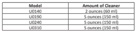
Wait until the clean cycle is complete (approximately 22 minutes) then press the On/Off button and disconnect power and water supplies to the ice machine.
- Step 4 Remove parts for cleaning.
Refer to the proper parts removal for your machine.
Continue with step 6 when the parts have been removed.
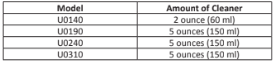
- Step 5 Mix a solution of cleaner and warm water. Depending on the amount of mineral buildup, a larger quantity of solution may be required. Use the ratio in the table below to mix enough solution to thoroughly clean all parts.
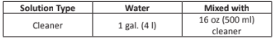
Use half of the cleaner and water solution to clean all components. The cleaner solution will foam when it contacts lime scale and mineral deposits; once the foaming stops, use a soft bristle brush, sponge, or cloth (not a wire brush) to carefully clean the parts. Soak the parts for 5 minutes (15 – 20 minutes for heavily scaled parts). Rinse all components with clean water.
- Step 6 While components are soaking, use half of the cleaner and water solution to clean all foodzone surfaces of the ice machine and bin. Use a nylon brush or cloth to thoroughly clean the following ice machine areas:
Evaporator plastic parts – including top, bottom, and sides
Bin bottom, sides, and top
Rinse all areas thoroughly with clean water.
- Step 7 Mix a solution of sanitizer and warm water.
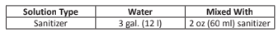
Use half of the sanitizer and water solution to sanitize all removed components. Use a spray bottle to liberally apply the solution to all surfaces of the removed parts or soak the removed parts in the sanitizer and water solution. Do not rinse parts after sanitizing.
- Step 8 Use half of the sanitizer and water solution to sanitize all foodzone surfaces of the ice machine and bin. Use a spray bottle to liberally apply the solution. When sanitizing, pay particular attention to the following areas:
Evaporator plastic parts - including top, bottom, and sides
Bin bottom, sides, and top
Do not rinse the sanitized areas.
- Step 9 Apply food grade lubricant to all o-rings, then replace all removed components. Wait 10 minutes and then reapply power and water to the ice machine
- Step 10 Press the Clean button. Water will flow through the water dump valve and down the drain. Wait until the water trough refills, then add the proper amount of ice machine sanitizer to the water trough.

Wait until the sanitize cycle is complete (approximately 22 minutes) then press the Ice button to start ice making.
REMOVE PARTS FOR CLEANING
A. Remove the ice thickness and harvest float switch.
Pull forward on the bottom of the bracket until clear of the tab, then slide bracket upward to remove the bracket and float switch as an assembly.
NOTE: At this point, the component can easily be cleaned. If complete removal is desired, follow the wires to the bulkhead grommet (exit point) in the back wall. Pull the wire connector through the bulkhead grommet, then disconnect the wire leads from the connector.
Important
Reversing the mounting location of the ice thickness and the harvest floats will result in a safety limit 2 failure.
- The ice thickness float must be mounted to the front of the water trough and the electrical connection must be in the top bulkhead grommet.
- The harvest float must be mounted to the side of the water trough and the electrical connection must be in the bottom bulkhead grommet.
- The wire connectors for each float are different and will not allow incorrect electrical bulkhead connection.
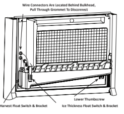
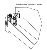
B. Remove water trough thermistor and water trough.
- While supporting the water trough, remove the upper thumbscrew and lift off the thermistor.
- Continue supporting the water trough and remove the thumbscrew from beneath the water trough.
- Remove the water trough from the bin area.
NOTE: At this point, the thermistor can easily be cleaned. If complete removal is desired, follow the wires to the bulkhead grommet (exit point) in the back wall. Pull the wire connector through the bulkhead grommet, then disconnect the wire leads from the connector.
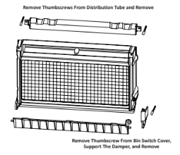
C. Remove the ice damper and water distribution tube.
- Remove thumbscrew from bin switch cover.
- Support ice damper and then pull bin switch cover and ice damper forward to remove.
- Remove thumbscrews from the water distribution tube, then remove.
PREVENTATIVE MAINTENANCE CLEANING
This cleaning procedure can be performed between the bi- annual cleaning and sanitizing cycles. This procedure does not require removing the ice from the bin.
- Step 1 Press the On/Off button after ice falls from the evaporator at the end of a Harvest cycle. Or, press the On/Off button and allow the ice to melt off the evaporator.
- Step 2 To start a cleaning cycle, press the Clean button. Water will flow through the water dump valve and down the drain. Wait until the water trough refills, then add the proper amount of ice machine cleaner to the water trough.
Wait until the clean cycle is complete (approximately 22 minutes) then press the On/Off button.
ICE MACHINE INSPECTION
- Check all water fittings and lines for leaks. Also, make sure the refrigeration tubing is not rubbing or vibrating against other tubing, panels, etc.
- Do not put anything (boxes, etc.) in front of the ice machine. There must be adequate airflow through and around the ice machine to maximize ice production and ensure long component life.
EXTERIOR CLEANING
- Clean the area around the ice machine as often as necessary to maintain cleanliness and efficient operation.
- Sponge any dust and dirt off the outside of the ice machine with mild soap and water. Wipe dry with a clean, soft cloth.
- Clean up any fallen ice or water spills as they occur.
CLEANING THE CONDENSER
A dirty condenser restricts airflow, resulting in excessively high operating temperatures. This reduces ice production and shortens component life.
- Clean the condenser at least every six months.
- Shine a flashlight through the condenser to check for dirt between the fins.
- Blow compressed air from the inside out (opposite direction of airflow).
- If dirt still remains, call a service agent to clean the condenser.
Removal from Service/Winterization
- Step 1 Clean and sanitize the ice machine.
- Step 2 Press the On/Off button to turn off the ice machine.
- Step 3 Turn off the water supply, disconnect and drain the incoming ice-making water line at the rear of the ice machine, and drain the water trough.
- Step 4 Energize the ice machine, wait one minute for the water inlet valve to open, and blow compressed air in both the incoming water and the drain openings in the rear of the ice machine to remove all water.
- Step 5 Press the On/Off button and disconnect the electric power at the circuit breaker or the electric service switch.
- Step 6 Fill spray bottle with sanitizer and spray all interior food zone surfaces. Do not rinse and allow to air dry.
- Step 7 Replace all panels.
Troubleshooting
Checklist
If a problem arises during operation of your ice machine, follow the checklist below before calling service. Routine adjustments and maintenance procedures are not covered by the warranty.
Ice machine does not operate.
- No electrical power to the ice machine.
Replace the fuse/reset the breaker/turn on the main switch/plug power cord into receptacle.
- Ice machine needs to be turned on.
Press the On/Off button to start ice making.
- Damper in open position (down).
Damper must be in upright position and capable of swinging freely.
Ice machine stops, and can be restarted by turning the ice machine OFF and then ON.
- Safety limit feature stopping the ice machine.
Refer to “Safety Limit Feature” on the next page.
Ice sheet is thick.
- Water trough level is too high.
Adjust ice thickness float.
- Power button was turned off/on during freeze cycle and ice remained on evaporator.
Allow ice to thaw and release from evaporator, then restart.
- Ice damper was opened then closed in the harvest cycle before the ice released.
Allow ice to thaw and release from evaporator, then restart.
- Long harvest cycles with repeated safety limit indication.
Call for service.
Ice machine does not release ice or is slow to harvest.
Clean and sanitize the ice machine.
- Ice machine is not level.
Level the ice machine.
- Low air temperature around ice machine (air- cooled models).
Air temperature must be at least 40°F (4°C).
- Water regulating valve leaks in harvest mode (water-cooled models).
Replace water regulating valve.
Ice machine does not cycle into harvest mode.
- Harvest float switch is dirty.
Clean and sanitize the ice machine.
- Harvest float switch wire is disconnected.
Connect the wire.
- Harvest float switch is out of adjustment.
Adjust the harvest float switch.
- Uneven ice fill (thin at top of evaporator).
See “Shallow or Incomplete Cubes” below.
Ice quality is poor (soft or not clear).
- Poor incoming water quality.
Contact a qualified service company to test the quality of the incoming water and make appropriate filter recommendations.
- Water filtration is poor.
Replace the filter.
Clean and sanitize the ice machine.
- Water softener is working improperly (if applicable).
Repair the water softener.
Ice machine produces shallow or incomplete cubes, or the ice fill pattern on the evaporator is incomplete.
- Ice thickness switch is out of adjustment.
Adjust the ice thickness switch.
- Water trough level is too high or too low.
Check the water level.
- Water filtration is poor.
Replace the filter.
Connect the ice machine to a cold water supply.
- Incorrect incoming water pressure.
Water pressure must be 20 – 80 psi (137.9 – 551.5 kPa)
- Ice machine is not level.
Level the ice machine.
Low ice capacity.
Clean the condenser.
- High air temperature around ice machine (air- cooled models).
Air temperature must not exceed 110°F (43°C).
- Inadequate clearance around the ice machine.
Provide adequate clearance.
- Objects stacked around ice machine, blocking airflow to condenser (air-cooled models)
Remove items blocking airflow.
Connect the ice machine to a cold water supply.
- Incorrect incoming water pressure. Water pressure is too low or water filter is restricted.
Water pressure must be 20 – 80 psi (137.9 – 551.5 kPa). Refer to section 2 for plumbing requirements. Replace water filter.
Safety Limit Feature
In addition to the standard safety controls, such as the high pressure cutout, your Manitowoc ice machine features built-in safety limits, which will stop the ice machine if conditions arise which could cause a major component failure.
Before calling for service, re-start the ice machine using the following procedure:
- Press the On/Off button and turn off the ice machine, then press the On/Off button again to start the ice machine.
A. If the safety limit feature has stopped the ice machine, it will restart after a short delay. Proceed to step 2.
B. If the ice machine does not restart, see “Ice machine does not operate” on the previous page.
- Allow the ice machine to run to determine if the condition is recurring.
A. If the ice machine stops again, the condition has recurred. Call for service.
B. If the ice machine continues to run, the condition has corrected itself. Allow the ice machine to continue running.