Part Number 000015433_03 5/20
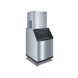
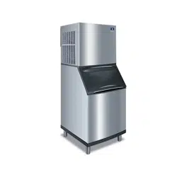
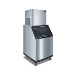
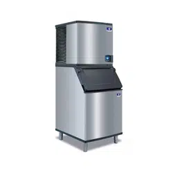
Flake & Nugget Models
RFF/UFF/RNF/UNF Ice Machines
Technician’s Handbook
Engineered for Ease


Safety Notices
Read these precautions to prevent personal injury:
• Read this manual thoroughly before operating,
installing or performing maintenance on the
equipment. Failure to follow instructions in this
manual can cause property damage, injury or death.
• Routine adjustments and maintenance procedures
outlined in this manual are not covered by the
warranty.
• Proper installation, care and maintenance are essential
for maximum performance and trouble-free operation
of your equipment.
• Visit our website www.manitowocice.com for manual
updates, translations, or contact information for
service agents in your area.
• This equipment contains high voltage electricity and
refrigerant charge. Installation and repairs are to be
performed by properly trained technicians aware of
the dangers of dealing with high voltage electricity
and refrigerant under pressure. The technician
must also be certified in proper refrigerant handling
and servicing procedures. All lockout and tag out
procedures must be followed when working on this
equipment.
• This equipment is intended for indoor use only. Do not
install or operate this equipment in outdoor areas.
• As you work on this equipment, be sure to pay close
attention to the safety notices in this handbook.
Disregarding the notices may lead to serious injury
and/or damage to the equipment.

n
Warning
Follow these electrical requirements during installation
of this equipment.
• All field wiring must conform to all applicable
codes of the authority having jurisdiction. It is
the responsibility of the end user to provide the
disconnect means to satisfy local codes. Refer to
rating plate for proper voltage.
• This appliance must be grounded.
• This equipment must be positioned so that the plug
is accessible unless other means for disconnection
from the power supply (e.g., circuit breaker or
disconnect switch) is provided.
• Check all wiring connections, including factory
terminals, before operation. Connections can
become loose during shipment and installation.

n
Warning
Follow these precautions to prevent personal injury
during installation of this equipment:
• Installation must comply with all applicable
equipment fire and health codes with the authority
having jurisdiction.
• To avoid instability the installation area must be
capable of supporting the combined weight of the
equipment and product. Additionally the equipment
must be level side to side and front to back.
• Remove all removable panels before lifting and
installing and use appropriate safety equipment
during installation and servicing. Two or more
people are required to lift or move this appliance to
prevent tipping and/or injury.
• Do not damage the refrigeration circuit when
installing, maintaining or servicing the unit.
• Connect to a potable water supply only.
• This equipment contains refrigerant charge.

n
Warning
Follow these precautions to prevent personal injury
while operating or maintaining this equipment.
• Refer to nameplate to identify the type of refrigerant
in your equipment.
• Only trained and qualified personnel aware of the
dangers are allowed to work on the equipment.
• Read this manual thoroughly before operating,
installing or performing maintenance on the
equipment. Failure to follow instructions in this
manual can cause property damage, injury or death.
• Crush/Pinch Hazard. Keep hands clear of moving
components. Components can move without
warning unless power is disconnected and all
potential energy is removed.
• Moisture collecting on the floor will create a
slippery surface. Clean up any water on the floor
immediately to prevent a slip hazard.

n
Warning
Follow these precautions to prevent personal injury
while operating or maintaining this equipment.
• Objects placed or dropped in the bin can affect
human health and safety. Locate and remove any
objects immediately.
• Never use sharp objects or tools to remove ice or
frost.
• Do not use mechanical devices or other means to
accelerate the defrosting process.
• When using cleaning fluids or chemicals, rubber
gloves and eye protection (and/or face shield) must
be worn.
DANGER
Do not operate equipment that has been misused,
abused, neglected, damaged, or altered/modified
from that of original manufactured specifications. This
appliance is not intended for use by persons (including
children) with reduced physical, sensory or mental
capabilities, or lack of experience and knowledge,
unless they have been given supervision concerning
use of the appliance by a person responsible for their
safety. Do not allow children to play with, clean or
maintain this appliance without proper supervision.

n
Warning
Follow these precautions to prevent personal injury
during use and maintenance of this equipment:
• It is the responsibility of the equipment owner to
perform a Personal Protective Equipment Hazard
Assessment to ensure adequate protection during
maintenance procedures.
• Do Not Store Or Use Gasoline Or Other Flammable
Vapors Or Liquids In The Vicinity Of This Or Any
Other Appliance. Never use flammable oil soaked
cloths or combustible cleaning solutions for
cleaning.
• All covers and access panels must be in place and
properly secured when operating this equipment.
• Risk of fire/shock. All minimum clearances must be
maintained. Do not obstruct vents or openings.
• Failure to disconnect power at the main power
supply disconnect could result in serious injury or
death. The power switch DOES NOT disconnect all
incoming power.
• All utility connections and fixtures must be
maintained in accordance with the authority having
jurisdiction.
• Turn off and lockout all utilities (gas, electric, water)
according to approved practices during maintenance
or servicing.

Table of Contents
Part Number 000015433_03 5/20 9
General Information
Model Numbers ................................. 15
Flake Air & Water-Cooled Models .............15
Nugget Air & Water-Cooled Models ...........15
QuietQube Models with Remote Condensing Unit .
.........................................16
Ice Machine Heat of Rejection.................... 16
Ice Machine Warranty Information ............... 17
Warranty Registration & Claim Procedures .....17
Model/Serial Number............................ 17
Manitowoc Cleaner/Descaler and Sanitizer ....... 18
Installation
Installation Requirements........................ 19
Potable Water Requirements..................... 20
Drain Connections ...............................20
Ice Machine Clearance Requirements............. 21
Cooling Tower Applications ......................21
Electrical Service................................. 22
Voltage...................................22
Fuse/Circuit Breaker ........................22
Ground Fault Interrupter Circuit (GFIC) ........22
Maximum Breaker/Minimum Circuit Amperage
Chart ............................................ 23
RFF/RNF/UFF/UNF Air-cooled Models .........23
RFF/RNF Water-cooled Models ...............23
RFF/RNF QuietQube Model Head Sections......24
RCUF QuietQube Model Condensing Units .....24

10 Part Number 000015433_03 5/20
Maintenance
Cleaning and Sanitizing .......................... 25
Exterior Cleaning...........................25
Detailed Descaling and Sanitizing Procedure ....25
Remedial Cleaning Procedure for Heavily Scaled Ice
Machines........................................ 30
Cleaning the Air filter and Condenser..........32
Removal from Service/Winterization .............33
Sequence of Operation
Ice Making Sequence of Operation ............... 35
UFF0200/UFF0350/UNF0200/UNF0300 Operation
.........................................35
RFF0320 & RNF0320 Operation...............35
RNF0620/RFF0620/RNF1100/RFF1300/RFF2500
Operation ................................36
RNF1020C/RFF1220C/RNF2000C/RFF2200C ....37
Thermostat Settings ............................. 39

Part Number 000015433_03 5/20 11
Troubleshooting
UFF0200/UFF0350/UNF0200/UNF0300
Troubleshooting ................................. 41
Self-Contained Air-Cooled ...................41
RFF0320/RNF0320 Troubleshooting .............. 47
Self-Contained Air-Cooled ...................47
RFF0620/RNF0620/RNF1100/RFF1300
Troubleshooting ................................. 53
Self-Contained Air-Cooled ...................53
Rotation Sensor Operation...................53
RNF1020C/RFF1220C Troubleshooting............59
QuietQube Remote Air-cooled Models with
Remote Condensing Unit ....................59
RFF2500 Troubleshooting ........................ 66
Self-Contained Air-Cooled ...................66
Rotation Sensor Operation...................66
RNF2000C/RFF2200C Troubleshooting............73
QuietQube Remote Air-cooled Models with
Remote Condensing Unit ....................73
Refrigeration Troubleshooting.................... 81
Capillary Tube Models ......................81
Thermostatic Expansion Valve Models . . . . . . . . .82

12 Part Number 000015433_03 5/20
Component Specifications
Bin Thermostat ............................83
Low Temperature Thermostat
Evaporator safety thermostat ................83
High Pressure Cutout (HPCO) Control ..........84
Rotation Sensor............................85
Low Pressure Cutout (LPCO) Control...........86
Fan Cycle Control ..........................86
Total System Refrigerant Charge ..............87
Filter-Driers ...............................88
Suction Cleanup Filter-Drier..................88
Charts
Ice Production & Refrigerant Pressure ............ 89
Flake Models .................................... 90
UFF200A .................................90
RFF0320A.................................91
UFF0350A ................................92
RFF0620A.................................93
RFF0620W ................................94
RFF1220C With RCUF1200...................95
RFF1300A.................................96
RFF1300W ................................97
RFF2200C With RCUF2200...................98
RFF2500A.................................99
Nugget Models .................................100
UNF0200A ...............................100
UNF0300A ...............................101
RNF0320A ...............................102
RNF0620A ...............................103
RNF0620W ..............................104
RNF1020C With RCUF1000 .................105
RNF1100A ...............................106
RNF1100W ..............................107
RNF2000C ...............................108

Part Number 000015433_03 5/20 13
Diagrams
Wiring Diagrams ................................109
Flake Models ...................................110
UFF0200A/UFF350A Air-Cooled .............110
RFF0320A/RFF0620A Air-Cooled .............112
RFF1220C QuietQube Head Section ..........114
RFF1300A Air-Cooled ......................116
RFF1300W Water-Cooled...................118
RNF2000C QuietQube Head Section..........120
RFF2200C QuietQube Head Section ..........122
RFF2500A Air-Cooled ......................124
Nugget Models .................................126
UNF0200A/UNF0300A Air-Cooled............126
RNF0320A Air-Cooled ......................128
RNF0620A Air-Cooled ......................130
RNF0620W Water-Cooled ..................132
RNF1020C QuietQube Head Section..........134
RNF1100A Air-Cooled ......................136
RNF1100W Water-cooled...................138
Condensing Units ...............................140
RCUF Condensing Unit 1ph .................140
RCUF Condensing Unit 3ph .................142
Compressor Start Component Wiring ...........144
UFF0200/UNF0200 ........................144
UNF0300/RFF0320/UFF0350/UNF0350/RFF0620 ..
........................................144
RFF1300/RFF2500.........................145

14 Part Number 000015433_03 5/20
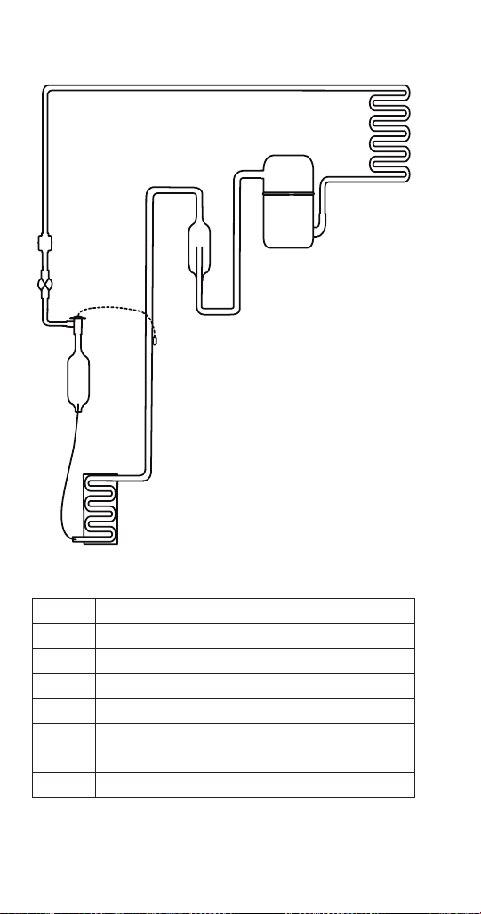
Refrigeration Tubing Schematics.................147
UFF0200/UFF0350/UNF0200/UNF0300 .......147
RFF0320/RNF0320 Air-cooled ...............148
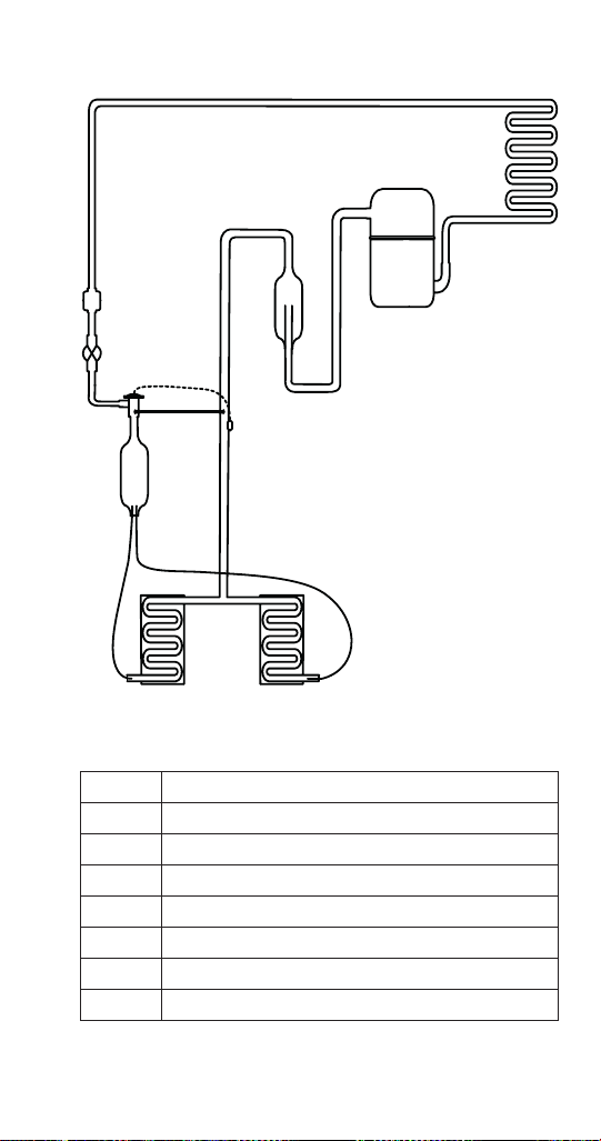
RFF0620/RNF0620/RNF1100 Air & Water-cooled ..
........................................149
RNF1020C QuietQube Head Section & RCUF1000
Condensing Unit ..........................150
RFF1220C & RCUF1000 Condensing Unit . . . . . .152
RNF2000C QuietQube Head Section & RCUF2200
Condensing Unit ..........................154
RFF2200C QuietQube Head Section & RCUF2200
Condensing Unit ..........................156
RFF1300 Air & Water-cooled ................158
RFF2500 Air-cooled........................159
Part Number 000015433_03 5/20 15
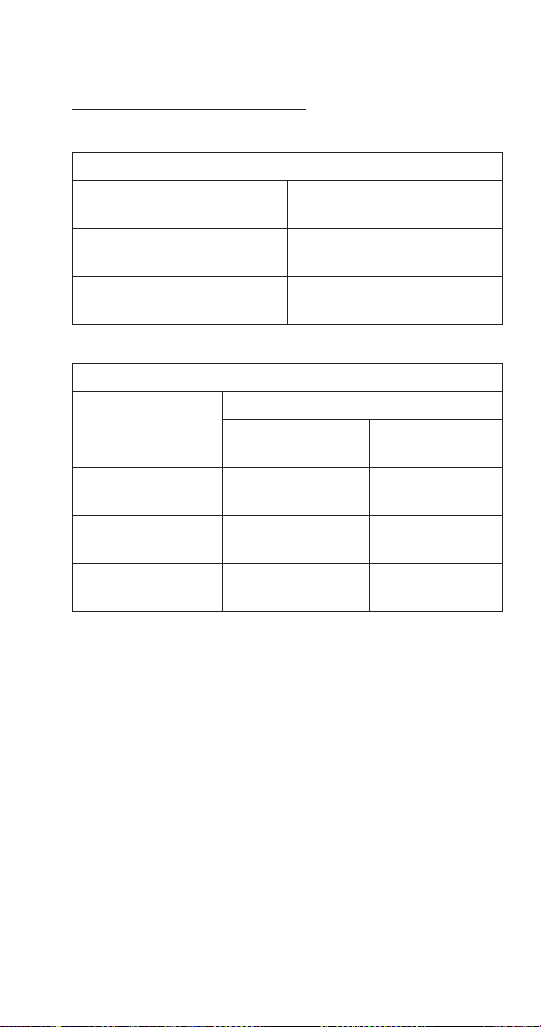
Model Numbers
FLAKE AIR & WATER-COOLED MODELS
Flake Models
Self Storage
Air-Cooled
Self Storage
Water-Cooled
Modular Air-
Cooled
Modular
Water-Cooled
UFF0200A – – –
UFF0350A – – –
– – RFF0320A –
– – RFF0620A RFF0620W
– – RFF1300A RFF1300W
– – RFF2500A –
NUGGET AIR & WATER-COOLED MODELS
Self Storage
Air-Cooled
Self Storage
Water-Cooled
Modular
Air-Cooled
Modular
Water-Cooled
UNF0200A – – –
UNF0300A – – –
UNF0300A – – –
– – RNF0320A –
– – RNF0620A RNF0620W
– – RNF1100A RNF1100W
General Information
16 Part Number 000015433_03 5/20
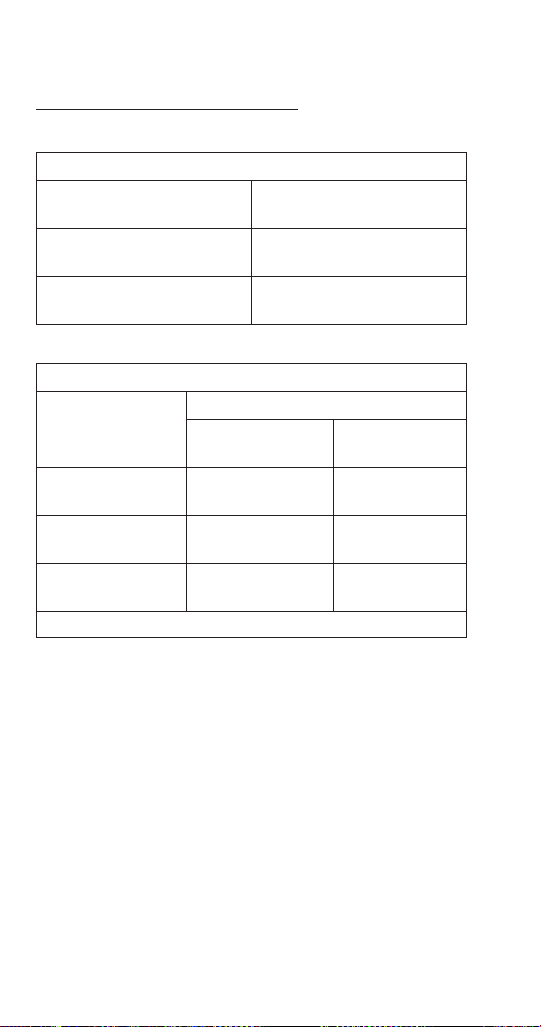
QUIETQUBE MODELS WITH REMOTE CONDENSING
UNIT
Flake Models
QuietQube Head RCUF Remote Condensing Unit
RFF1220C RCUF1200
RFF2200C RCUF2200
Nugget Models
QuietQube Head RCUF Remote Condensing Unit
RNF1020C RCUF1000
RNF2000C RCUF2200
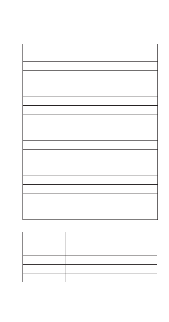
Ice Machine Heat of Rejection
Series Ice Machine Heat of Rejection BTU/Hour
UFF0200 - RFF0320 2400
UNF0200 2800
UNF0300 - UFF0350 5000
RNF0320 3075
RFF0620 - RNF0620 5200
RNF1100 - RFF1300 7500
RFF2500 17000

Part Number 000015433_03 5/20 17
Ice Machine Warranty Information
For warranty information visit: www.manitowocice.com/
Service/Warranty
• Warranty Coverage Information
• Warranty Registration
• Warranty Verification
Warranty coverage begins the day the ice machine is
installed.
WARRANTY REGISTRATION & CLAIM PROCEDURES
Scan the QR code with your smart device or enter the link
in a web browser to access:
• Warranty registration
• Warranty information
• Warranty labor claim form
WWW.MANITOWOCICE.COM/SERVICE/WARRANTY#WARRANTY-
REGISTRATION
Model/Serial Number
These numbers are required when requesting information
from your local Manitowoc Distributor, or Manitowoc Ice.
The model and serial number are listed on the MODEL/
SERIAL NUMBER DECAL affixed to the ice machine.

18 Part Number 000015433_03 5/20
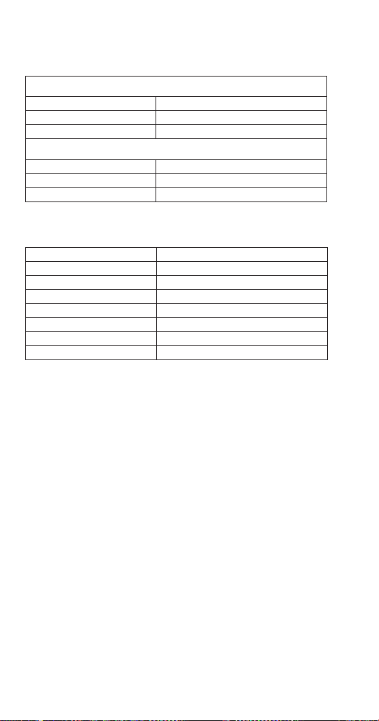
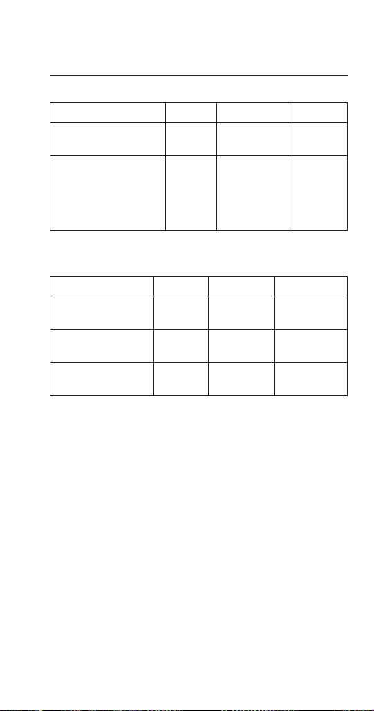
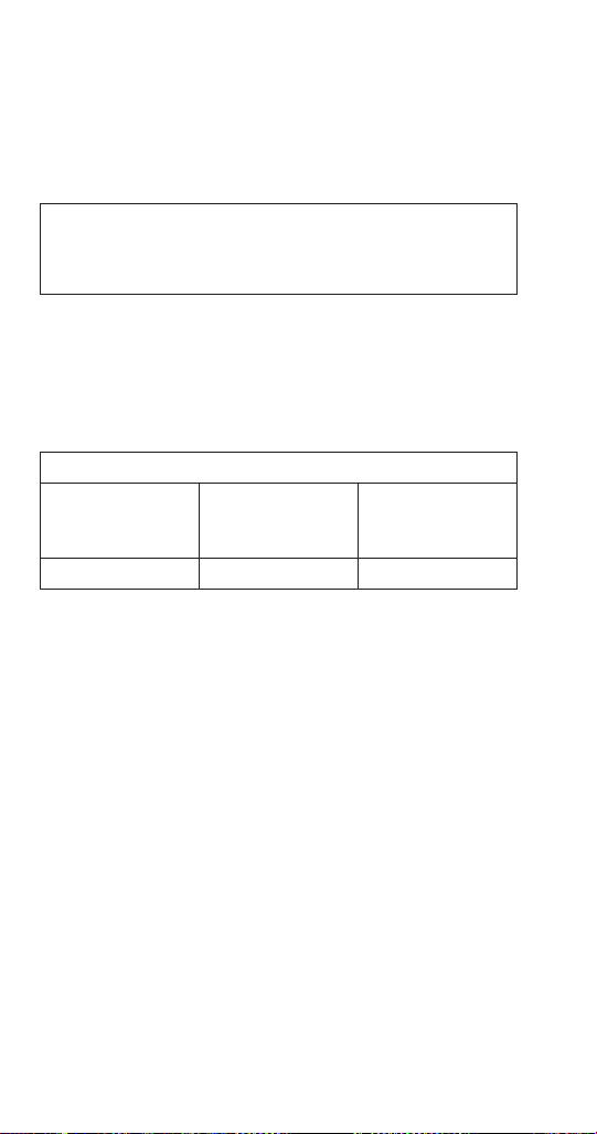
Manitowoc Cleaner/Descaler and Sanitizer
Manitowoc Ice Machine Cleaner/Descaler and Sanitizer
are available in 16 oz. (473 ml) bottles. These are the only
cleaner and sanitizer approved for use with Manitowoc
products.
Cleaner/Descaler Part Number Sanitizer Part Number
16 oz. 000000084 16 oz. 9405653
1 gal N/A 1 gal. 9405813

Part Number 000015433_03 5/20 19
Installation Requirements
The location selected for the ice machine must meet the
following criteria. If any of these criteria are not met,
select another location.
• Air temperature - Minimum 50°F (10°C), Maximum
110°F (43°C)
• The location must be free of airborne and other
contaminants.
• The location must not be near heat-generating
equipment or in direct sunlight.
• The location must be capable of supporting the weight
of the ice machine and a full bin of ice.
• The location must allow enough clearance for water,
drain and electrical connections in the rear of the ice
machine.
• The location must not obstruct airflow through or
around the ice machine.
• The ice machine and bin must be level.
• Routine adjustments and maintenance procedures
outlined in this manual are not covered by the
warranty.
Installation

20 Part Number 000015433_03 5/20
Potable Water Requirements
• Plumbing must conform to local codes.
• Water temperature: Minimum 37°F (3°C), Maximum
90°F (32°C).
• Do not connect the ice machine to a hot water supply.
Be sure all hot water restrictors installed for other
equipment are working. (Check valves on sink faucets,
dishwashers, etc.)
• If water pressure exceeds maximum pressure (80 psig
[552 kPa] obtain a water pressure regulator.
• A water shut-off valve is required to clean the ice
machine.
• A union for both the ice making and condenser water
lines is required.
• Water inlet lines require insulation to prevent
condensation.
• When local code requires, a back flow preventer must
be installed on the water inlet line.
Drain Connections
• Drain lines must have a 1.5 inch drop per 5 feet of run
(2.5 cm per meter), and must not create traps.
• The floor drain must be large enough to accommodate
drainage from all drains.
• Bin drain termination must have an air gap.
• Separate insulated bin and water-cooled condenser
drain lines are required.
• The bin and ice machine drains must be run separately.
Part Number 000015433_03 5/20 21
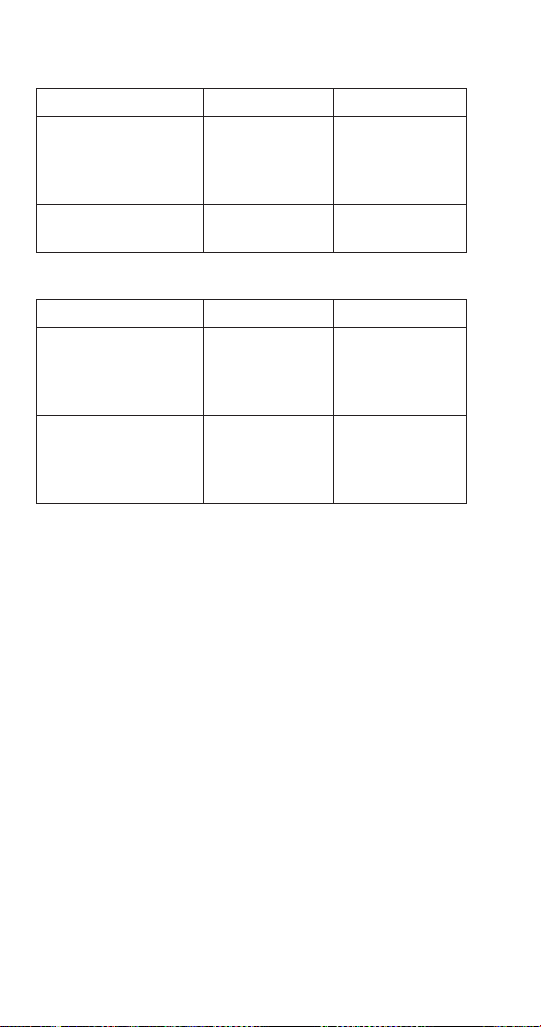
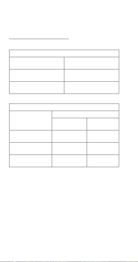
Ice Machine Clearance Requirements
All Models Clearance Requirements
Back 5” (12.7 cm)
Sides/Top 8” (20.3 cm)
RCUF Units Remote Condensing Unit
Front/Back 24” (61.0 cm)
Sides/Top 6” (15.2 cm)
24 inches clearance on top
and sides is recommended for
serviceability
NOTE: Allowance must be made for removal when the ice
machine is built-in. Removal of the top panel is required
for cleaning and sanitizing.
Cooling Tower Applications
A water cooling tower installation does not require
modification of the ice machine. The water regulator valve
for the condenser continues to control the refrigeration
discharge pressure.
It is necessary to know the amount of heat rejection, and
pressure drop through the condenser and water valves
(inlet and outlet) when using a cooling tower on an ice
machine.
• Water entering the condenser must not be lower than
37°F (3°C) or exceed 90°F (32°C).
• Water flow through the condenser must not exceed 5
gal. (19 L) per minute.
• Allow for a pressure drop of 7 psi (48 kPa) between
the condenser water inlet and the outlet of the ice
machine.
• Water exiting the condenser must not exceed 110°F
(43°C).
• Water entering the condenser must not exceed 84 psi
(6 bar).

22 Part Number 000015433_03 5/20
Electrical Service
n
Warning
All wiring must conform to local, state and national
codes.
VOLTAGE
The maximum allowable voltage variation is ± 10% of the
rated voltage on the ice machine model/serial number
plate at compressor start-up.
FUSE/CIRCUIT BREAKER
A separate fuse/circuit breaker must be provided for each
ice machine. Circuit breakers must be H.A.C.R. rated (does
not apply in Canada).
n
Warning
The ice machine must be grounded in accordance with
national and local electrical codes.
GROUND FAULT INTERRUPTER CIRCUIT (GFIC)
A GFCI/GFI circuit protection is not recommended with
our equipment. If a GFCI/GFI is required by code a GFCI/
GFI breaker rather than outlet must be used to avoid
intermittent nuisance trips.
Part Number 000015433_03 5/20 23
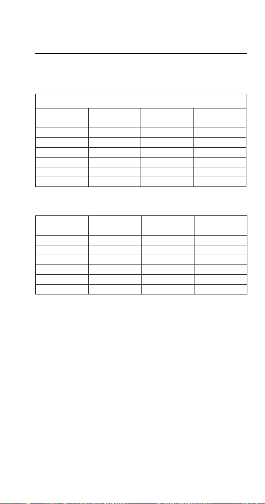
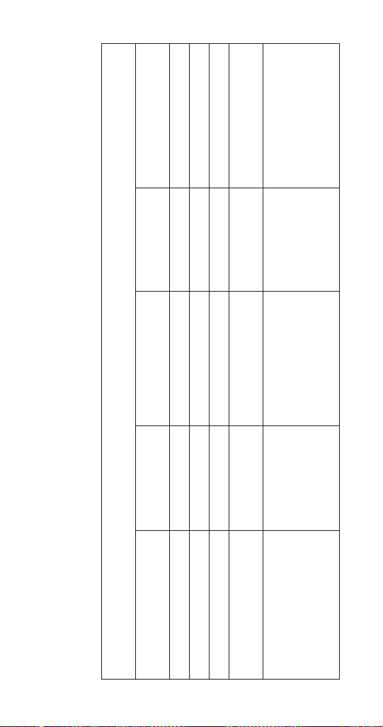
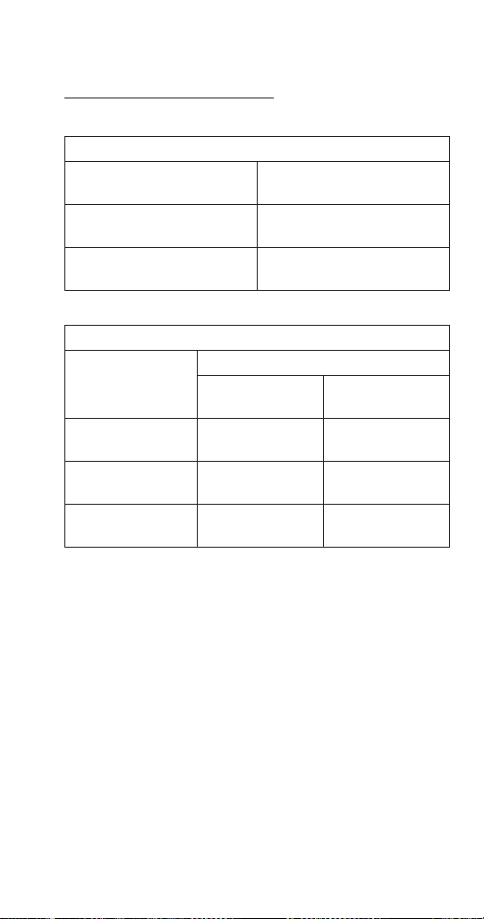
Maximum Breaker/Minimum Circuit Amperage
Chart
NOTE: Due to continuous improvements, this information
is for reference only. Please refer to the ice machine serial
number tag to verify electrical data. Model/Serial tag
information overrides information listed on these pages.
RFF/RNF/UFF/UNF AIR-COOLED MODELS
Series Ice
Machine
Voltage
Phase
Cycle
Air-Cooled
Max
Fuse/
Circuit Breaker
Min
Circuit
Amps
Total
Circuit
Amps
Series Ice
Machine
Voltage
Phase
Cycle
Air-Cooled
Max
Fuse/
Circuit Breaker
Min
Circuit
Amps
Total
Circuit
Amps
UNF0200 115/1/60 15 Amp N/A 7.5
UFF0200 115/1/60 15 Amp N/A 7.5
UFF0350 115/1/60 15 Amp N/A 10.0
UNF0300 115/1/60 15 Amp N/A 10.0
RNF0320 115/1/60 20 Amp 12.8 —
RFF0320 115/1/60 20 Amp 12.8 —
RNF0620 115/1/60 25 Amp 16.3 —
RFF0620 115/1/60 25 Amp 16.3 —
RNF1100 208-230/1/60 20 Amp 14.2 —
RFF1300 208-230/1/60 20 Amp 12.5 —
RFF2500 208-230/3/60 20 Amp 15.0 —
RFF/RNF WATER-COOLED MODELS
Series Ice
Machine
Voltage Phase
Cycle
Water-Cooled
Max
Fuse/
Circuit Breaker
Min
Circuit
Amps
RNF0620 115/1/60 25 Amp 15.4
RFF0620 115/1/60 25 Amp 15.4
RNF1100 208-230/1/60 20 Amp 13.7
RFF1300 208-230/1/60 20 Amp 12.5

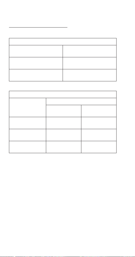
24 Part Number 000015433_03 5/20
RFF/RNF QUIETQUBE MODEL HEAD SECTIONS
Series Ice
Machine
Voltage Phase
Cycle
Remote Air-Cooled
Max
Fuse/
Circuit Breaker
Total
Circuit
Amps
RNF1020C 115/1/60 15 Amp 2.9
RFF1220C 208-230/1/60 15 Amp 1.4
RNF2000C 208-230/1/60 15 AMP 3.2
RFF2200C 208-230/1/60 15 Amp 3.2
RCUF QUIETQUBE MODEL CONDENSING UNITS
Condensing
Unit
Voltage Phase
Cycle
Remote Air-Cooled
Max
Fuse/
Circuit Breaker
Total
Circuit
Amps
RCUF1000
208-230/1/60
208-230/3/60
15 15
RCUF1200
208-230/1/60
208-230/3/60
15 15
RCUF2200 208-230/3/60 15 15

Part Number 000015433_03 5/20 25
Cleaning and Sanitizing
Maintenance procedures covered in this manual are not
covered by the warranty.
,
Caution
Use only Manitowoc approved Ice Machine Cleaner/
Descaler (part number 000000084) and Sanitizer (part
number 9405653). Do not mix Cleaner/Descaler and
Sanitizer solutions together. It is a violation of Federal
law to use these solutions in a manner inconsistent with
their labeling. Read and understand all labels printed on
bottles before use.
n
Warning
Wear rubber gloves and safety goggles (and/or face
shield) when handling ice machine Cleaner or Sanitizer.
EXTERIOR CLEANING
Remove dust and dirt off exterior surfaces with mild
household dish-washing detergent and warm water. Wipe
dry with a clean, soft cloth.
DETAILED DESCALING AND SANITIZING PROCEDURE
This procedure must be performed once every 6 months.
• All ice must be removed from the bin
• The ice machine and bin must be disassembled
descaled and sanitized
• The ice machine produces ice with the cleaner/
descaler and sanitizer solutions
• All ice produced during the descaling and sanitizing
procedure must be discarded
Maintenance
26 Part Number 000015433_03 5/20
Detailed Descaling and Sanitizing Procedure
Use Ice Machine Cleaner/Descaler part number
000000084.
Use Ice Machine Sanitizer part number 9405653.
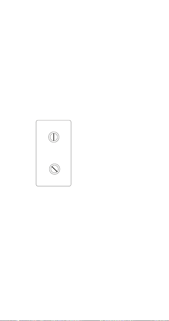
Step 1 Remove front and top covers and set the toggle
switch to the OFF position.
Step 2 Remove all ice from the bin.
Step 3 Turn off the ice making water supply and drain
water from evaporator and reservoir.
Step 4 Remove the top cover from water reservoir.
Step 5 Follow the chart and premix cleaner and water.
Amount of Water Amount of Cleaner/Descaler
Part Number 000000084
1 gallon (4 Liters) 3 ounces (90 ml)
Step 6 Fill the evaporator and reservoir with descaling
solution.
Important
Prop Float Up to Prevent Low Water Level Shutdown
Part Number 000015433_03 5/20 27
Step 7 Move the toggle switch to the ON position. The
ice machine will make ice with the descaling solution and
deposit the ice in the bin. Add the remaining descaler/
water solution as the water level in the reservoir drops.
NOTE: Do not allow the descaler/water solution level to
drop below the minimum water level. The ice machine will
discontinue the cycle if the water float switch opens.
Step 8 After all of the descaler/water solution has
been added turn on the ice making water supply. Continue
the freeze cycle for 10 minutes to remove the solution
from the water circuit.
Step 9 Place the toggle switch in the OFF position and
turn off the ice making water supply.
Step 10 Remove the following components for hand
descaling and sanitizing for RFF and RNF models.
A. Remove water reservoir cover.
B. Remove microswitch and bin thermostat from
the ice chute.
C. Remove retainer, ice chute elbow and ice chute.
28 Part Number 000015433_03 5/20
D. Hand descale the removed part(s) in a properly
mixed solution of descaler and water.
Solution Type Water Mixed With
Descaling 1 gal. (4 L) 16 oz (500 ml) Cleaner/Descaler
Part Number 000000084
E. Use a soft-bristle brush or sponge (NOT a wire
brush) to carefully clean the parts.
F. Use the solution and a brush or sponge to clean
all disassembled components and the inside of
the bin.
G. Rinse all cleaned parts with clear potable water.
H. Mix a solution of sanitizer and water.
Solution Type Water Mixed With
Sanitizer 3 gal. (11 L) 2 oz (60 ml) sanitizer
Part Number 94-0565-3
I. Use the sanitizer/water solution and a sponge to
sanitize all removed components and the inside
of the bin. Do not rinse the sanitized parts.
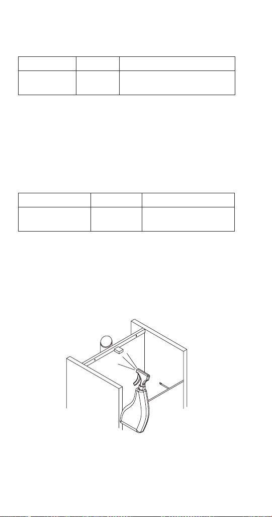
NOTE: Descale, rinse and spray sanitizer on all interior and
exterior areas of the evaporator discharge spout on UFF
and UNF models.

Part Number 000015433_03 5/20 29
Step 11 Reassemble all components removed in step 10
into the ice machine.
Step 12 Refer to chart and premix water and sanitizer.
Amount of Water Amount of Sanitizer
1 Gallons (4 L) Water 1/2 ounce (15 ml)
Step 13 Fill the evaporator and reservoir with sanitizer/
water solution.
Important
Prop Float Up to Prevent Low Water Level Shutdown
Step 14 Move the toggle switch to the ON position. The
ice machine will make ice with the sanitizer/water solution
and deposit the ice in the bin. Add the remaining sanitizer/
water solution when the water level in the reservoir drops.
NOTE: Do not allow the sanitizer/water level to drop below
the minimum water level. The ice machine will discontinue
the cycle if the water float switch opens.
Step 15 After all of the sanitizer/water solution has
been added to the reservoir, turn on the ice making water
supply.
Step 16 Continue the freeze cycle for 30 minutes and
then discard all ice produced.

30 Part Number 000015433_03 5/20
Remedial Cleaning Procedure for Heavily
Scaled Ice Machines
Perform this procedure if you have some or all of these
symptoms.
• Excessive grinding, popping or squealing noises from
the evaporator
• Grinding noise from gearbox
• Ice machine trips speed sensor
NOTE: A Cleaning/Sanitizing Procedure must be performed
after this procedure.
Procedure to Clean Heavily Scaled Flake Ice Machines
Step 1 Remove front and top covers and set the toggle
switch to the OFF position.
Step 2 Remove all ice from the bin.
Step 3 Turn off the ice making water supply.
Step 4 Remove the top cover from water reservoir.
Part Number 000015433_03 5/20 31
Step 5 Refer to chart and premix cleaner/descaler
with lukewarm water in a non-metallic container.
Model Water
Reservoir
Capacity
Mix Cleaner/Descaler and
Water
Use Ice machine cleaner/
descaler, part number
000000084 only
Cleaner Water
UNF0200
UFF0200
UFF0350
UNF0300
14 oz (400 ml) 9 oz (266 ml) 5 oz (148 ml)
RNF0320
RFF0320
RNF0620
RFF0620
17 oz (500 ml) 11 oz (325 ml) 6 oz (177 ml)
RNF1020C
RNF1100
RFF1220C
RFF1300
34 oz (1 L) 23 oz (680 ml) 11 oz (325 ml)
RNF2000C
RFF2200C
RFF2500
68 oz (2 L) 46 oz (1.3 L) 22 oz (650 ml)
Step 6 Remove all water from the evaporator and
water reservoir. Add the entire descaler/water solution
and re-install the reservoir cover.
Leave the descaler/water solution in the evaporator for a
minimum of 4 hours.
Step 7 Remove all descaler/water solution from the
evaporator and water reservoir.
Step 8 Perform the detailed descaling and sanitizing
procedure.

32 Part Number 000015433_03 5/20
CLEANING THE AIR FILTER AND CONDENSER
n
Warning
Disconnect electric power to the ice machine at the
electric service switch before cleaning the condenser.
The condenser fins are sharp. Use care when cleaning
them.
Air-Cooled Condenser
Clean the condenser at least every six months. Follow the
steps below.
1. Some models have a washable filter. Clean the filter
with a mild soap and water solution.
2. Shine a flashlight through the condenser to check
for dirt between the fins. Blow compressed air
through the condenser fins from the inside or use
a commercial condenser coil cleaner. Follow the
directions and cautions supplied with the cleaner.
3. Straighten any bent condenser fins with a fin comb.
4. Carefully wipe off the fan blades and motor with
a soft cloth. Do not bend the fan blades. If the fan
blades are excessively dirty, wash with warm, soapy
water and rinse thoroughly.
n
Warning
If you are cleaning the condenser fan blades with water,
cover the fan motor to prevent water damage.

Part Number 000015433_03 5/20 33
Removal from Service/Winterization
,
Caution
If water is allowed to remain in the ice machine
in freezing temperatures, severe damage to some
components could result. Damage of this nature is not
covered by the warranty.
Follow the procedure below.
1. Disconnect the electric power at the circuit breaker or
the electric service switch.
2. Turn off the water supply.
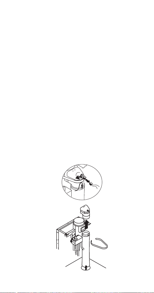
3. Disconnect and drain the incoming ice-making water
line at the rear of the ice machine.
4. Disconnect drain tubing and drain water into
container and discard.
5. Make sure water is not trapped in any of the water or
drain lines.
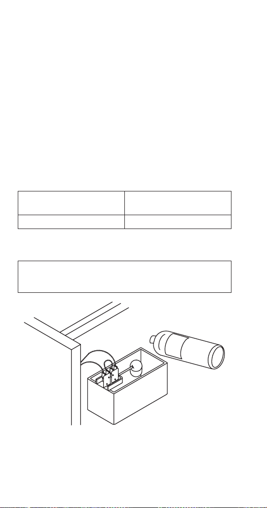
6. Water cooled - Use compressed air to remove all
water from the condenser.


Part Number 000015433_03 5/20 35
Ice Making Sequence of Operation
NOTE: Flake ice machines use an auger to remove ice from
the evaporator. Occasional noises (creaks, groans, squeaks,
or pops) are a normal part of the ice making process.
UFF0200/UFF0350/UNF0200/UNF0300 OPERATION
The ice machine will not start until:
A. The rocker switch is moved to “ON”.
B. Ice does not contact the bin thermostat bulb.
C. The water reservoir is full of water.
Placing the toggle switch in the ON position starts the gear
motor and refrigeration system. The float valve controls
the water inlet valve and water level. The freeze cycle ends
when ice contacts the bin thermostat. The ice machine will
restart when ice no longer contacts the bin thermostat.
RFF0320 & RNF0320 OPERATION
When the toggle switch is placed in the “ON” position the
following controls must be in the closed position before
the ice machine will start:
A. Bin Thermostat
B. Ice Chute Safety Switch
C. Low Water Level Switch
D. High Pressure Cut-out Switch
E. Low Pressure Cut-Out Switch
Placing the toggle switch in the ON position starts the
gear motor and an 8 minute compressor time delay. The
compressor starts and the float valve controls the water
inlet valve and water level. The freeze cycle ends when ice
contacts the bin thermostat. The ice machine remains off
until ice no longer contacts the bin thermostat.
Sequence of Operation

36 Part Number 000015433_03 5/20
RNF0620/RFF0620/RNF1100/RFF1300/RFF2500
OPERATION
When the toggle switch is placed in the ON position the
following controls must be in the closed position before
the ice machine will start:
A. Bin Thermostat
B. High Pressure Cut-out Switch
C. Ice Chute Safety Switch
D. Low Pressure Switch
E. Low Water Level Switch
Placing the toggle switch in the ON position starts the
gear motor. After 8 minutes of correct rotation, the time
delay ends and the compressor starts. The ice machine will
continue to make ice until ice contacts the bin thermostat.
The ice machine remains off until ice no longer contacts
the bin thermostat.

Part Number 000015433_03 5/20 37
RNF1020C/RFF1220C/RNF2000C/RFF2200C
Remote Air-cooled Condensing Unit Models
When the toggle switch is placed in the ON position the
following controls must be in the closed position before
the ice machine will start:
A. Bin Thermostat
B. High Pressure Cut-out Switch
C. Ice Chute Safety Switch
D. Low Pressure Switch
E. Low Water Level Switch
Placing the toggle switch in the ON position starts the gear
motor. After 8 minutes of correct rotation the time delay
ends and the liquid line solenoid valve opens.
• When the refrigerant pressure is high enough to close
the low-pressure control the contactor coil energizes
and the compressor and condenser fan motor starts.
The ice machine will continue to make ice until ice contacts
the bin thermostat and the liquid line solenoid valve closes
and the refrigeration system pumps down.
• The refrigerant pressure drops and the fan cycling
pressure control opens stopping the.
• When the refrigerant pressure is low enough to open
the low pressure control, the contactor coil is de-
energized and the compressor and condenser fan
motor stop.
The ice machine remains off until ice no longer contacts
the bin thermostat.

38 Part Number 000015433_03 5/20
Ice Production/Quality Check
QUALITY CHECK
Ice quality varies with ambient and water temperatures,
and is measured by the amount of water in the ice.
Generally speaking, higher incoming water temperature
results in lower ice quality. Lower water temperature
results in higher ice quality.
ICE PRODUCTION CHECK
NOTE: Ice production checks that are within 10% of the
charted capacity are considered normal due to variances
in air and water temperatures. Actual temperatures will
seldom match the chart exactly.
1. Run the ice machine a minimum of 10 minutes to
allow the system to stabilize.
2. Catch the ice in a non-perforated container for 7
minutes and 12 seconds or for more accuracy 14
minutes and 24 seconds.
3. Weigh the container and ice, then deduct the weight
of the container.
4. Convert ounces to pounds.
5. Example: 3 lbs. 12 oz. converts to 3.75 lbs.
6. (12 oz. ÷ 16 oz. =.75 lb.)
7. Determine the 24-hour ice production capacity.
A. 7 minutes 12 seconds = Multiply the total ice
weight by 200.
B. 14 minutes 24 seconds = Multiply the total ice
weight by 100.
Part Number 000015433_03 5/20 39
Thermostat Settings
Bin Thermostat:
The bin thermostat sensing bulb is located in the ice chute
on modular models and in the bin thermostat holder on
the right side of the bin on self storage models. The bin
thermostat turns the ice machine on and off as the level
of ice in the bin changes. Use the indicator on the ice
machine label as the initial setting and adjust as required.
Evaporator Low Temperature Safety Thermostat:
The evaporator low temperature safety thermostat
protects the ice machine if the evaporator temperature is
too cold. Refer to chart for correct setting.
1
2
3
4
5
6
7
1
2
3
4
5
6
7
Bin Thermostat
Small Numbers = Less ice in bin
Large Numbers = More ice in bin
Start at Chart Setting, then adjust
as required
Evaporator Low Temperature
Safety Thermostat
Refer to chart for setting
Incorrect settings will cause ice
machine to shut off prematurely
40 Part Number 000015433_03 5/20
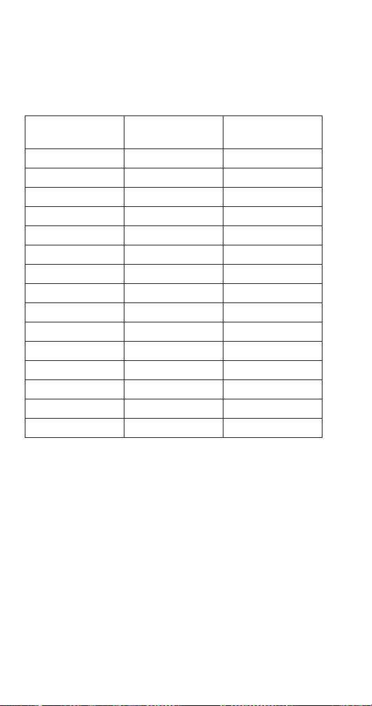
Thermostat Setting Chart
NOTE: Settings are for reference only. Factory setting is
indicated on control label and overrides information listed
on this page.
Model Bin Thermostat
Setting
Evaporator
Thermostat Setting
UNF0200 5 6
UFF0200 5 5
UNF0300 5 6
RFF0320 3 7
RNF0320 5 6
UFF0350 5 7
RNF0620 2 --
RFF0620 3 --
RNF1020C 3 --
RNF1100 3 --
RFF1220C 3 --
RFF1300 3 --
RNF2000C 3 --
RFF2200C 3 --
RFF2500 3 --

Part Number 000015433_03 5/20 41
Diagnostic troubleshooting for the ice machine involves
following flowcharts that are dependent on symptoms of
the failed machine.
Follow the flowcharts for the failure symptom and model
you are working on.
NOTE: Refer to the sequence of operation to determine
where in the sequence the ice machine has failed. An
example would be an ice machine that energizes the gear
motor, but the compressor does not energize. Following
the electrical flowchart will quickly and easily eliminate
non issues.
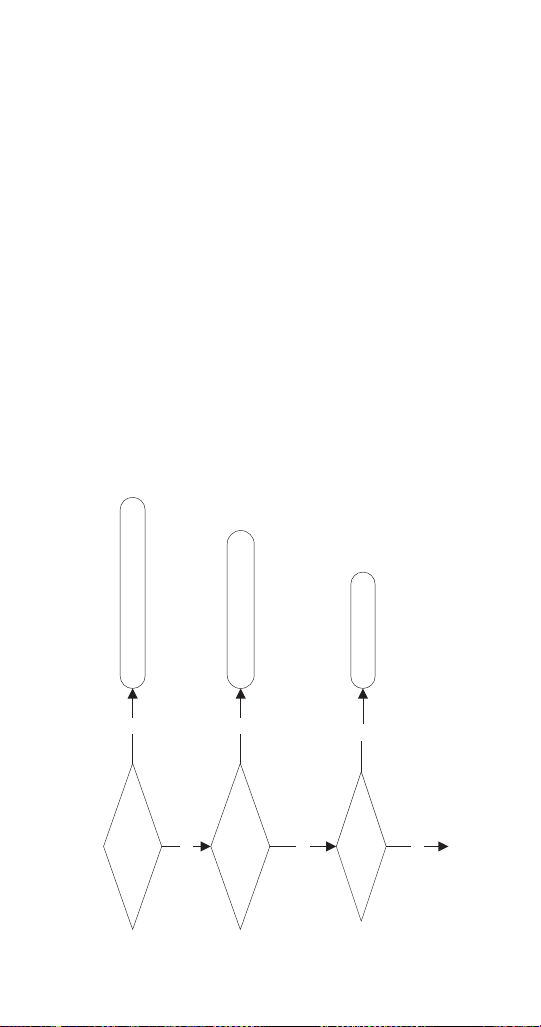
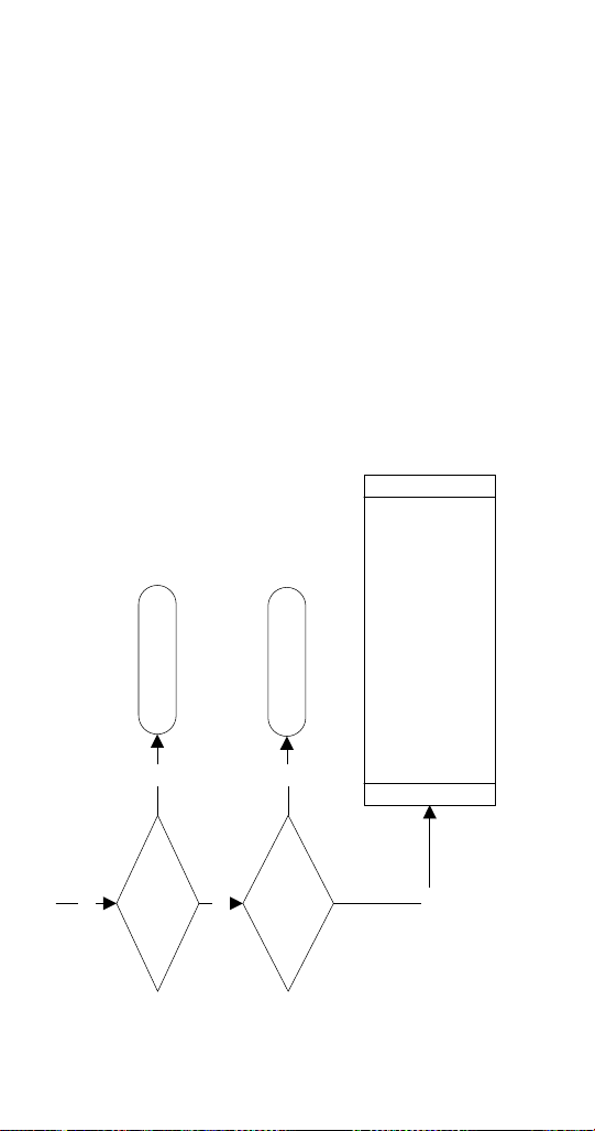
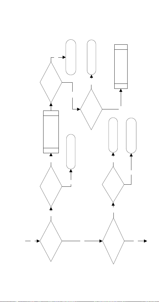
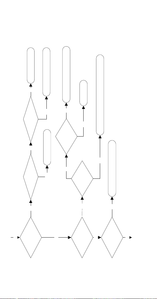
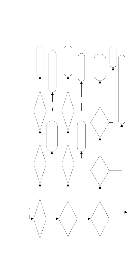
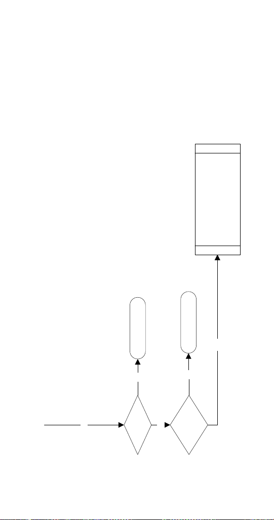
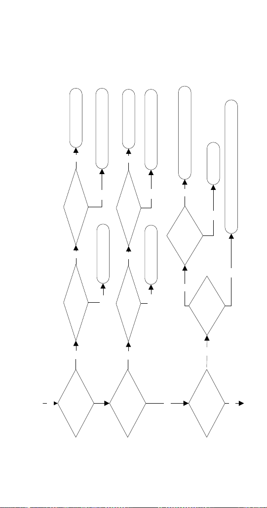
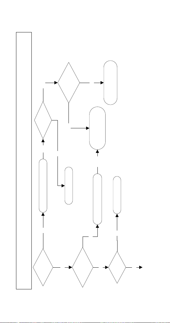
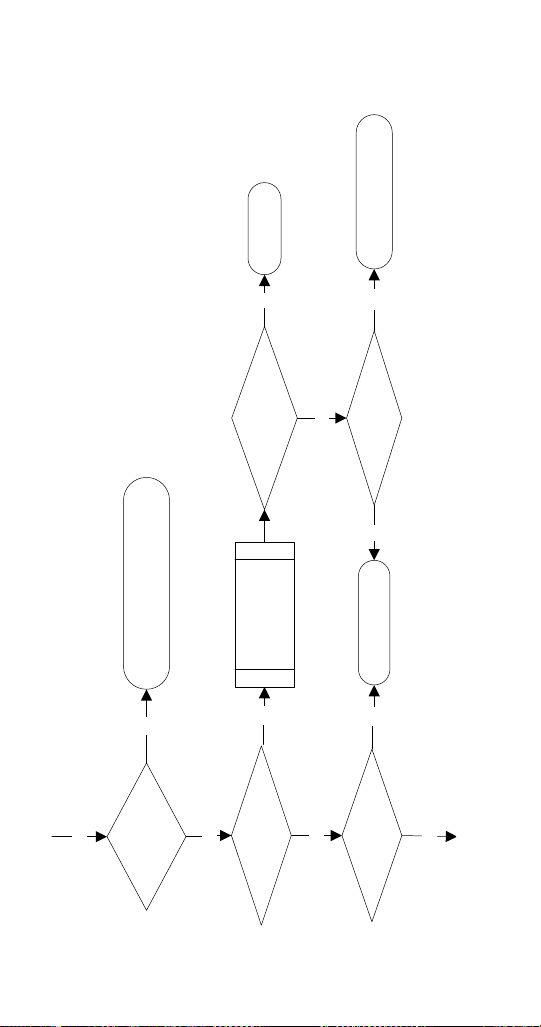
UFF0200/UFF0350/UNF0200/UNF0300
Troubleshooting
SELF-CONTAINED AIR-COOLED
Normal Operation
When the toggle switch is placed in the “ON” position the
following controls must be in the closed position before
the ice machine will start:
A. Bin Thermostat
B. Low Evaporator Temperature Thermostat
C. Low Water Level Switch
NOTE: Placing the toggle switch in the ON position starts
the gear motor and refrigeration system. The float valve
controls the water inlet valve and water level. The freeze
cycle ends when ice contacts the bin thermostat. The ice
machine will restart when ice no longer contacts the bin
thermostat.
Troubleshooting
Part Number 000015433_03 5/20 43
YES
Bin Thermostat
Closed?
NO
Replace Thermostat
Ice Contacting
Thermostat?
Remove Ice - Allow
To Warm And Retest
Adjusting Closes
Thermostat?
Verify New Setting Cycles
Machine On/O
Yes
No
No
Yes
Evaporator Safety
Thermostat Closed?
NO
Evaporator Cold?
Replace Thermostat
Allow Evaporator To
Warm And Retest
Adjusting Closes
Thermostat?
Verify New Setting Cycles
Machine On/O
Yes
No
No
Yes
YES
YES
RF0266 LPCO
Part Number 000015433_03 5/20 45
Wiring From
Gearmotor Intact?
Line Voltage To
Compressor Relay
Coil?
Gear Motor Runs? NO
YES
NO
YES
Line Voltage To
Gear motor?
Repair WiringNo
Remove Auger
From Evaporator
Ice In Evaporator?
Gear Motor Runs?
Replace Gear Motor
Yes
No
Rebuild
Evaporator
Thaw Evaporator
Yes
Yes
No
Replace Gear Motor
Repair Wiring
Yes
No

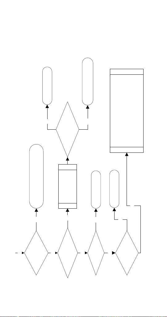
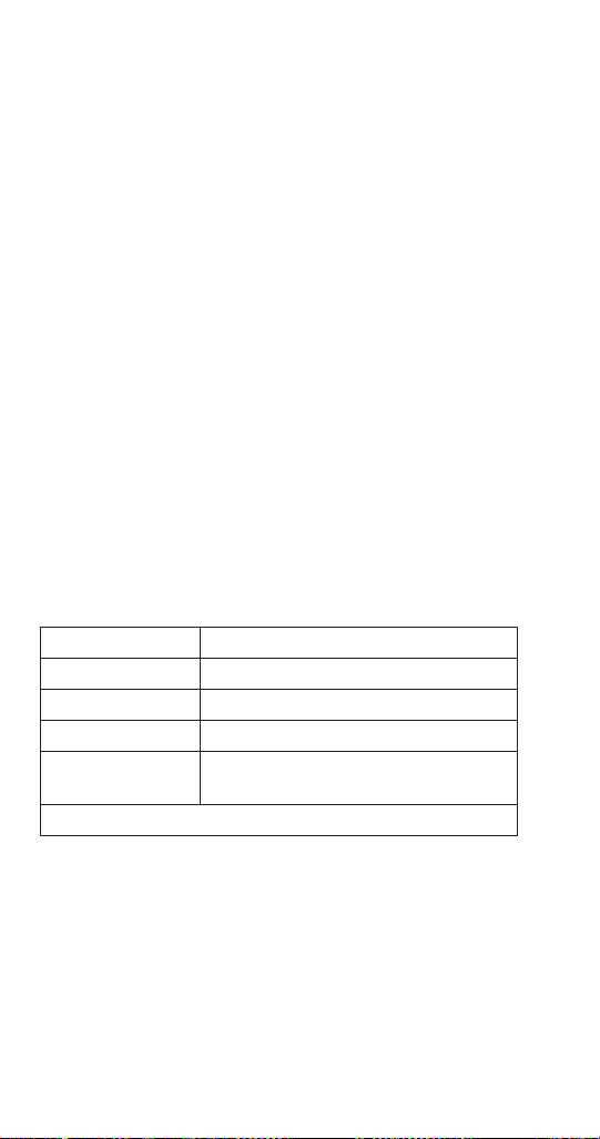
Part Number 000015433_03 5/20 47
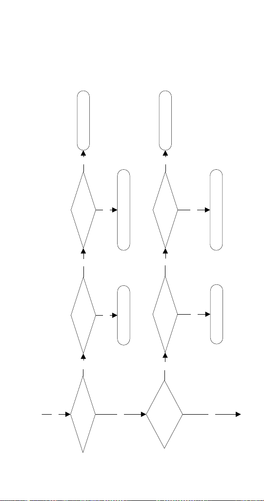
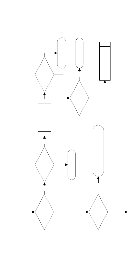
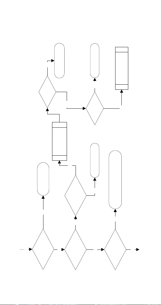
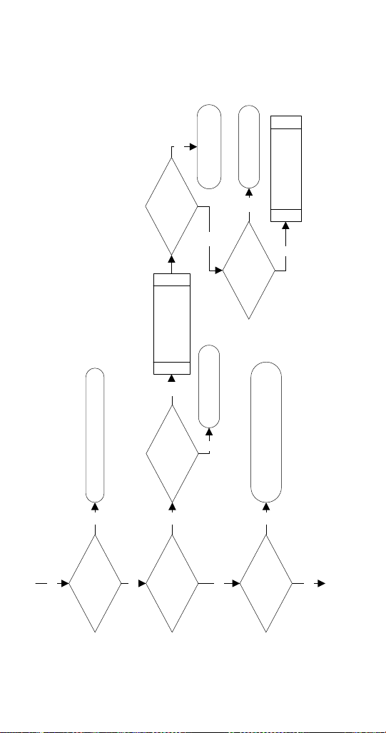
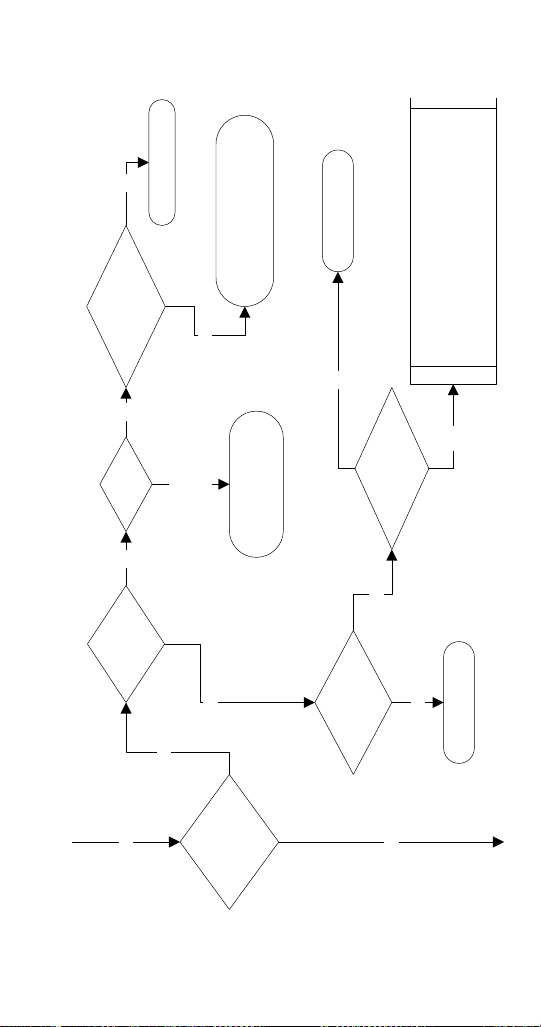
RFF0320/RNF0320 Troubleshooting
SELF-CONTAINED AIR-COOLED
When the toggle switch is placed in the “ON” position the
following controls must be in the closed position before
the ice machine will start:
A. Bin Thermostat
B. Ice Chute Safety Switch
C. Low Water Level Switch
D. High Pressure Cut-out Switch
E. Low Pressure Cut-Out Switch
Placing the toggle switch in the ON position starts the
gear motor and an 8 minute compressor time delay. The
compressor starts and the float valve controls the water
inlet valve and water level. The freeze cycle ends when ice
contacts the bin thermostat. The ice machine remains off
until ice no longer contacts the bin thermostat.
Part Number 000015433_03 5/20 49
Bin Thermostat
Closed?
NO
Replace Thermostat
YES
Low Pressure
Switch Closed?
NO
Chute Switch
Closed?
NO
YES
Ice Contacting
Thermostat?
Remove Ice - Allow
To Warm And Retest
Adjusting Closes
Thermostat?
Verify New Setting Cycles
Machine On/Off
Yes
No No
Yes
Evaporator Cold?
Replace LPCO
Allow Evaporator To
Warm And Retest
Refrigerant Pressure
Below Cut-out?
Repair Refrigerant Leak,
Evacuate, Recharge
Yes
No
No
Yes
Adjust Or Replace
Actuator
Ice Contacting
Actuator?
Remove Ice And
Retest
Actuator Functions?
Replace Switch
Yes
No No
Yes
Yes
Yes
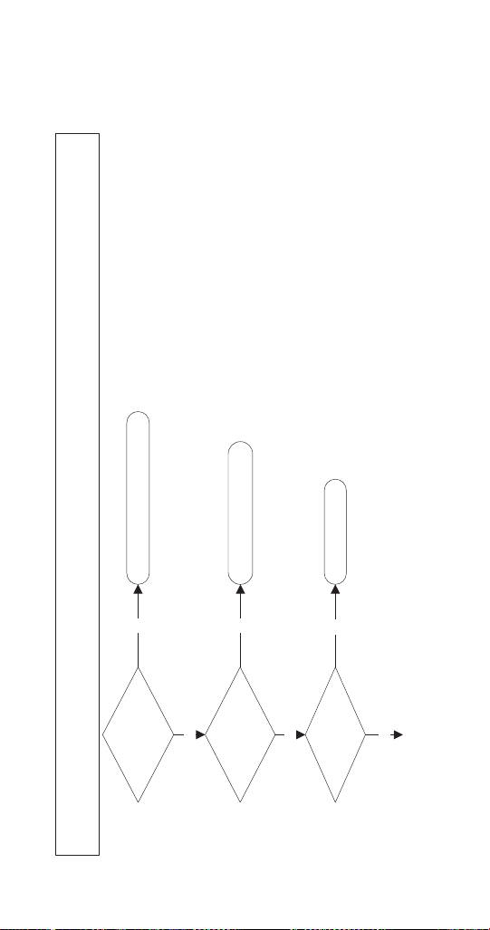
Part Number 000015433_03 5/20 51
Gear Motor Runs? NO
YES
Line Voltage To
Gear motor?
Repair WiringNo
Disconnect
Evaporator From
Gear Motor
Ice In Evaporator?
Gear Motor Runs?
Replace Gear Motor
Yes
No
Rebuild
Or
Replace Evaporator
Thaw Evaporator
Yes
Yes
No
Yes
Gear Motor
Centrifugal Switch
Closed?
Line Voltage To
Compressor Time
Delay?
NO
Repair Wiring
Replace Gear Motor
Yes
No
YES
52 Part Number 000015433_03 5/20
Contactor Closed?
Line Voltage To
Compressor?
YES
YES
NO
YES
NO
Verify:
Compressor Overload is Closed
Start Components Function
Fan Cycling Control Functions
Condenser Fan Motor Functions
Water cooled only:
Water Regulating Valve Functions
Repair Wiring
Replace Contactor
Line Voltage To
Compressor Contactor
Coil?
NO
Repair Wiring
Replace Time Delay Relay
No
10 Minute Time
Delay Expired?
NO
Wait 10 Minutes - Do Not Install
Compressor Time Delay Jumper
Yes
Power To Contactor Coil?
Yes
Install
Compressor Time
Delay Jumper
Yes

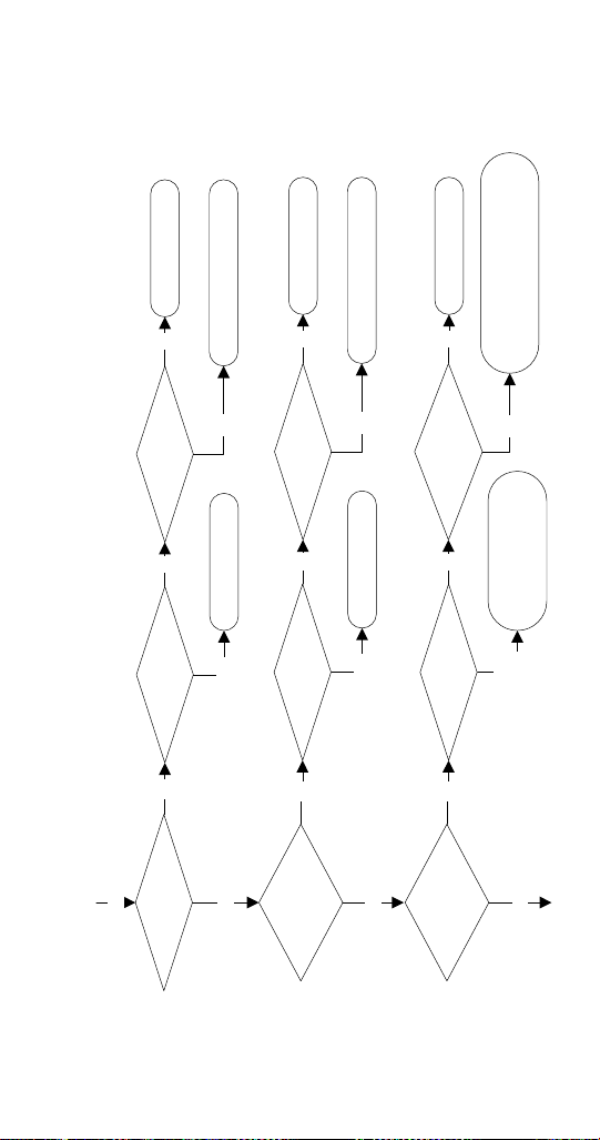
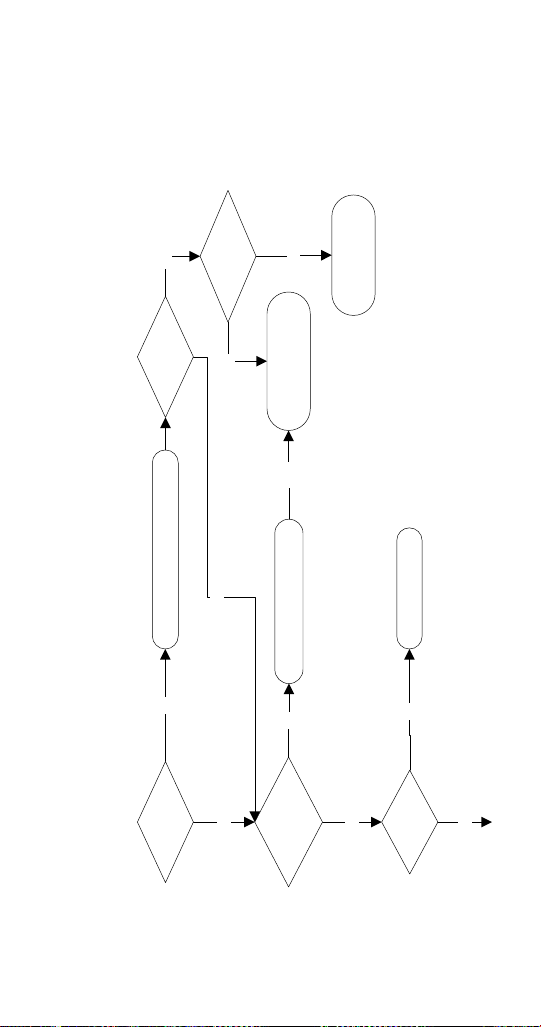
Part Number 000015433_03 5/20 53
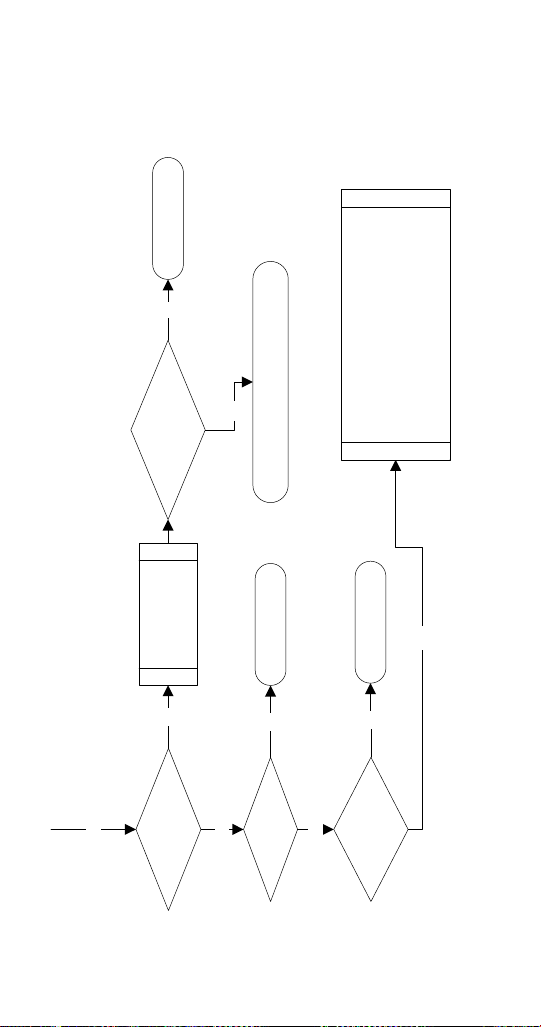
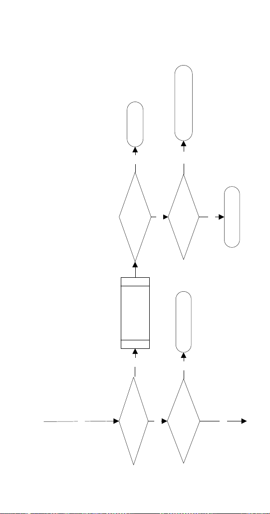
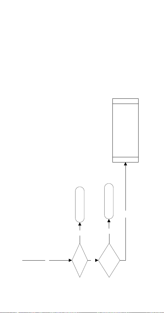
RFF0620/RNF0620/RNF1100/RFF1300
Troubleshooting
SELF-CONTAINED AIR-COOLED
Normal Operation
When the toggle switch is placed in the ON position the
following controls must be in the closed position before
the ice machine will start:
A. Bin Thermostat
B. High Pressure Cut-out Switch
C. Ice Chute Safety Switch
D. Low Pressure Switch
E. Low Water Level Switch
NOTE: Placing the toggle switch in the ON position starts
the gear motor. After 8 minutes of correct rotation the
time delay ends and the compressor starts. The ice
machine will continue to make ice until ice contacts the bin
thermostat. The ice machine remains off until ice no longer
contacts the bin thermostat.
ROTATION SENSOR OPERATION
Light Definition
Yellow Blinking Time Delay Period
Yellow Solid Normal Operation Sensing
Red Blinking 2
Flashes Per Second
Time Delay Period - First 1 To 7 Faults
Red Solid Lockout - 8 Consecutive Faults Due To A
Speed Fault
Remove/Restore Power To Reset
Red Blinking Slowly Lockout - 8 Consecutive Faults Due To A
Short Circuit
See “Rotation Sensor” on page 85 for sequence of operation
Part Number 000015433_03 5/20 55
Bin Thermostat
Closed?
NO
Replace Thermostat
YES
Low Pressure
Control Closed?
NO
YES
Ice Contacting
Thermostat?
Remove Ice - Allow
To Warm And Retest
Adjusting Closes
Thermostat?
Verify New Setting Cycles
Machine On/Off
Yes
No No
Yes
Evaporator Cold?
Replace LPCO
Allow Evaporator To
Warm And Retest
Refrigerant Pressure
Below Cut-out?
Repair Refrigerant Leak,
Evacuate, Recharge
Yes
No
No
Yes
Yes
High Pressure
Control Closed?
NO
YES
Resets?
Replace HPCO
Clean Condenser,
Check Fan Motor
Check Fan Cycle Control
Refrigerant Pressure
Above Cut-out?
Clean Condenser,
Check Fan Motor,
Check FCC & Refrigeration System
Resets
&
Trips
No
No
Yes
56 Part Number 000015433_03 5/20
Low Water Level
Switch Closed?
YES
NO
Reservoir Full Of
Water?
NO
Restore Water Supply / Replace Water Inlet Valve
Replace Switch or Float Assembly
Power To Water
Inlet Valve?
Yes
Water Level
Switch Closed?
No No
Repair WiringYes
YES
Replace Switch or Float Assembly
Chute Switch
Closed?
NO
Adjust Or Replace
Actuator
Ice Contacting
Actuator?
Remove Ice And
Retest
Actuator Functions?
Replace Switch
Yes
No No
Yes
Yes
YES
Part Number 000015433_03 5/20 57
Gear Motor Runs? NO
YES
Line Voltage To
Gear motor?
Repair Wiring
No
Disconnect
Evaporator From
Gear Motor
Ice In Evaporator?
Gear Motor Runs?
Replace Gear Motor
Yes
No
Rebuild
Or
Replace Evaporator
Thaw Evaporator
Yes
Yes
No
Yes
YES
10 Minute Time
Delay Expired?
NO
Wait 10 Minutes - Do Not Install
Compressor Time Delay Jumper
58 Part Number 000015433_03 5/20
Contactor Closed?
Line Voltage To
Compressor?
YES
YES
NO
YES
NO
Verify:
Compressor Overload is Closed
Start Components Function
Fan Cycling Control Functions
Condenser Fan Motor Functions
Water cooled only:
Water Regulating Valve Functions
Repair Wiring
Replace Contactor
Line Voltage To
Compressor Contactor
Coil?
NO
Repair Wiring
Replace Rotation Sensor/Time Delay Relay
No
Yes
Power To Contactor Coil?
Yes
Install
Compressor Time
Delay Jumper

Part Number 000015433_03 5/20 59
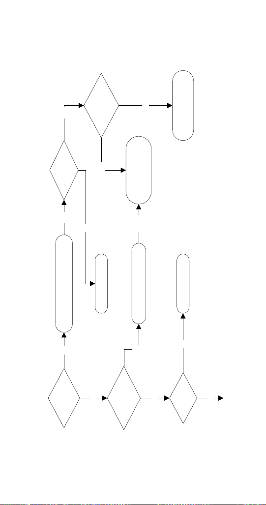
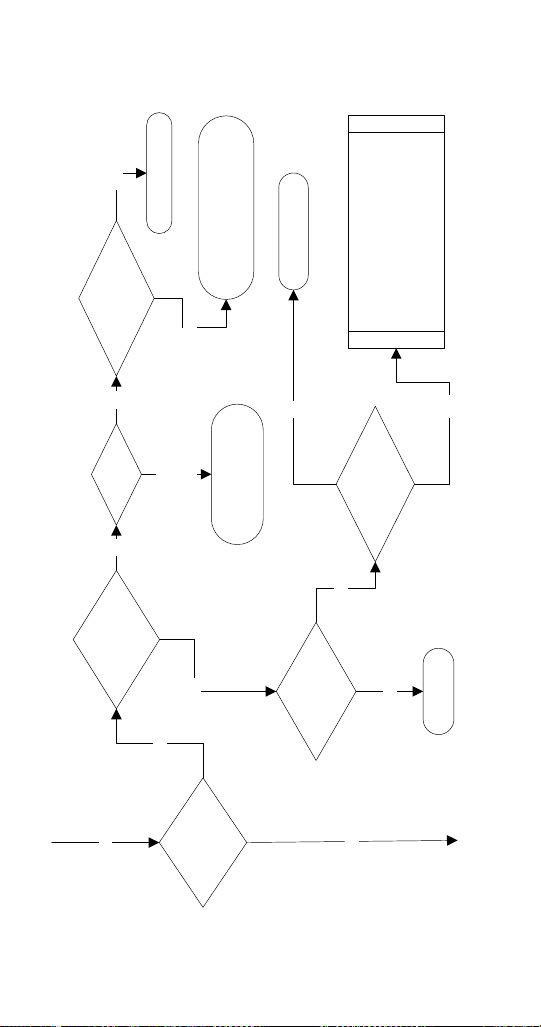
RNF1020C/RFF1220C Troubleshooting
QUIETQUBE REMOTE AIR-COOLED MODELS WITH
REMOTE CONDENSING UNIT
Normal Operation
When the toggle switch is placed in the ON position the
following controls must be in the closed position before
the ice machine will start:
A. Bin Thermostat
B. High Pressure Cut-out Switch
C. Ice Chute Safety Switch
D. Low Pressure Switch
E. Low Water Level Switch
Placing the toggle switch in the ON position starts the gear
motor. After 8 minutes of correct rotation the time delay
ends and the liquid line solenoid valve opens.
The refrigerant pressure will increase and close the fan
cycling pressure control and the condenser fan motor
starts.
The ice machine will continue to make ice until ice contacts
the bin thermostat and the liquid line solenoid valve closes
and the refrigeration system pumps down.
When the refrigerant pressure is low enough to open the
low pressure control, the contactor coil is de-energized and
the compressor stops.
NOTE: The ice machine remains off until ice no longer
contacts the bin thermostat.
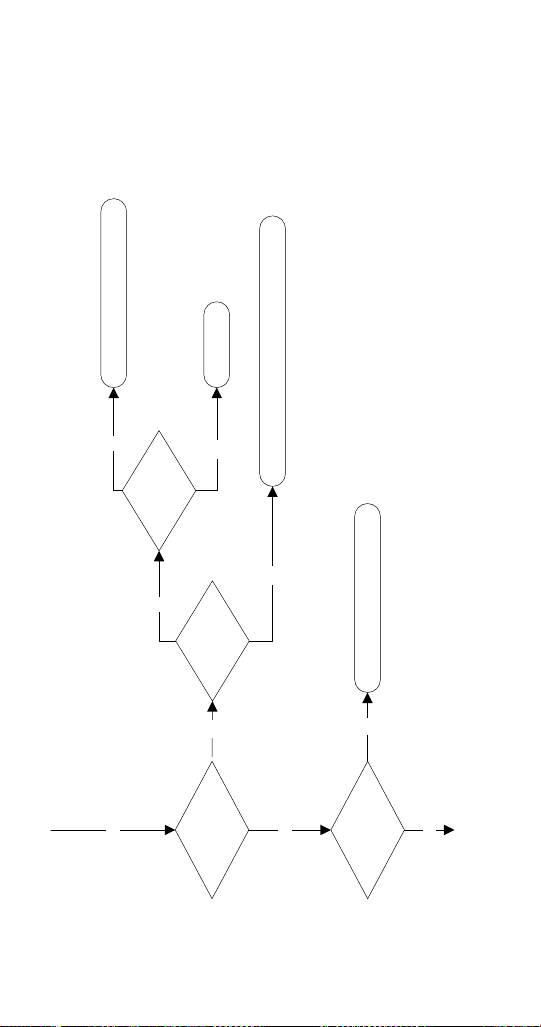
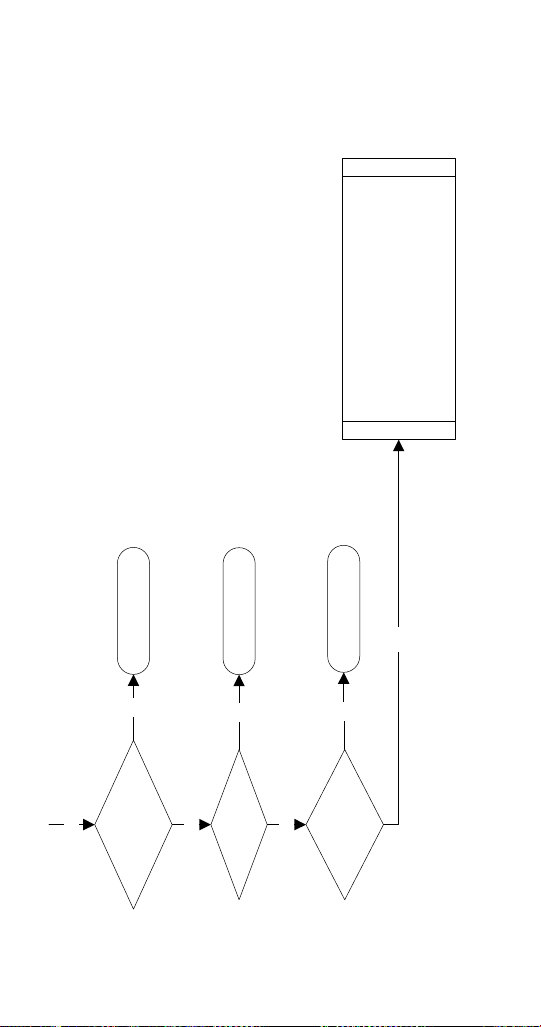
60 Part Number 000015433_03 5/20
Power Supplied
to Ice Machine?
Toggle Switch In
ON Position?
Move Switch To ON Position
Restore Power, Reset BreakerNO
NO
YES
Electrical Flowchart - RNF1020C/RFF1220C QuietQube
Switch
Illuminated?
NO
YES
Replace Switch
Immediately
Trips?
YES
YES
NO
Toggle Switch In
Off Position?
Isolate And Ohm Each
Component - Then Each
Wire If Required
NO
TRIPS
YES
Isolate And Ohm Switch
Check Wiring From Panel
Test Run
YES
Part Number 000015433_03 5/20 61
Bin Thermostat
Closed?
NO
Replace Thermostat
YES
Ice Contacting
Thermostat?
Remove Ice - Allow
To Warm And Retest
Adjusting Closes
Thermostat?
Verify New Setting Cycles
Machine On/Off
YES
NO NO
YES
YES
Chute Switch
Closed?
NO
Adjust Or Replace
Actuator
Ice Contacting
Actuator?
Remove Ice And
Retest
Actuator Functions?
Replace SwitchYES
NO NO
YES
Yes
YES
Reservoir Full Of
Water?
NO
Restore Water Supply / Replace Water Inlet Valve
Power To Water
Inlet Valve?
YES
Water Level
Switch Closed?
NO NO
Repair Wiring
Replace Switch or
Float Assembly
YES
62 Part Number 000015433_03 5/20
Low Water Level
Switch Closed?
NO
Replace Switch or
Float Assembly
Gear Motor Runs? NO
Line Voltage To
Gear motor?
Repair WiringNO
Disconnect
Evaporator From
Gear Motor
Gear Motor
Runs?
Replace Gear Motor
YES
NO
YES
YES
Ice In
Evaporator?
Rebuild
Or
Replace Evaporator
Thaw EvaporatorYES
NO
YES
YES
YES
10 Minute Time
Delay Expired?
NO
Wait 10 Minutes - Do Not Install
Compressor Time Delay Jumper
Part Number 000015433_03 5/20 63
YES
NO
Replace Relay
NO
Repair Wiring
Replace Rotation
Sensor/Time Delay
NO
Power To Left Time
Delay Relay Coil?
Install
Compressor Time
Delay Jumper On
Left Evaporator
Delay Relay Contacts
Closed?
Delay Relay Contacts
Closed?
Yes
NO
YES
YES
Line Voltage To
Left Delay Relay Coil?
YES
Replace Relay
64 Part Number 000015433_03 5/20
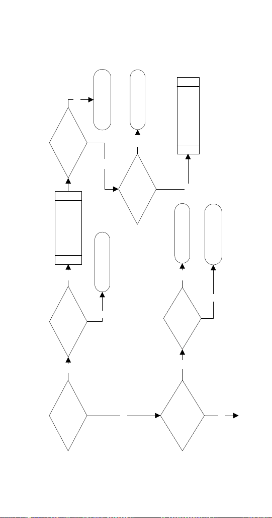
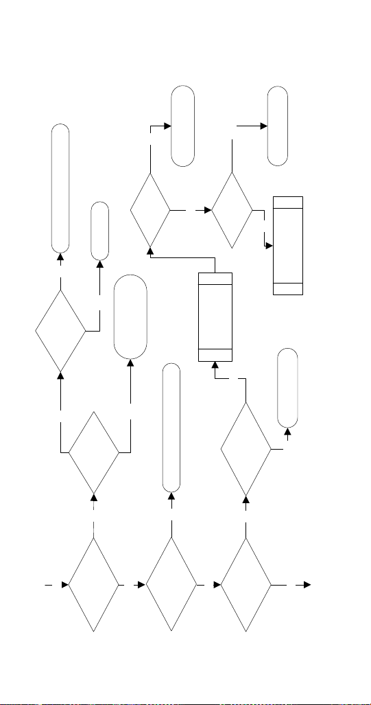
Low Pressure
Control Closed?
Line Voltage At
Liquid Line Solenoid
Valve?
NO
NO
YES
Verify:
Refrigerant Pressure is Higher Than
LPCO Cut-in
Both Shut-off Valves are Open
Repair/Replace Liquid Line Solenoid
Locate and Repair Refrigerant Leak
Replace LPCO Switch
Replace Relay
YES
High Pressure
Control Closed?
NO Resets?
Replace HPCO
Clean Condenser,
Check Fan Motor
Check Fan Cycle Control
Refrigerant Pressure
Above Cut-out?
Clean Condenser,
Check Fan Motor,
Check Fan Cycle Control &
Refrigeration System
Resets
&
Trips
NO NO
YES
NO
Line Voltage To
Compressor
Contactor Coil?
YES
YES
YES
Repair Wiring
66 Part Number 000015433_03 5/20
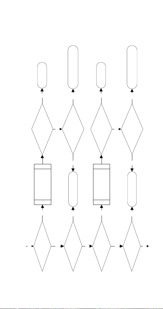
RFF2500 Troubleshooting
SELF-CONTAINED AIR-COOLED
Normal Operation
When the toggle switch is placed in the ON position the
following controls must be in the closed position before
the ice machine will start:
A. Bin Thermostat
B. High Pressure Cut-out Switch
C. Ice Chute Safety Switch
D. Low Pressure Switch
E. Low Water Level Switch
Placing the toggle switch in the ON position starts the
gear motor. After 8 minutes of correct rotation the time
delay ends and the compressor starts. The ice machine will
continue to make ice until ice contacts the bin thermostat.
The ice machine remains off until ice no longer contacts
the bin thermostat.
ROTATION SENSOR OPERATION
Light Definition
Yellow Blinking Time Delay Period
Yellow Solid Normal Operation Sensing
Red Blinking Fault Time Delay Period
Red Solid Lockout - 8 Consecutive Faults
Remove/Restore Power To Reset
See “Rotation Sensor” on page 85 for sequence of operation
Part Number 000015433_03 5/20 67
Power Supplied
to Ice Machine?
Toggle Switch In
ON Position?
Move Switch To ON Position
Restore Power, Reset BreakerNO
NO
YES
Electrical Flowchart – RF2500 Air-cooled
Switch
Illuminated?
NO
YES
Replace Switch
Immediately
Trips?
Yes
Ohm Compressor
Crankcase Heater
And Toggle Switch
Yes
No
Toggle Switch In
Off Position?
Isolate And Ohm Each
Component - Then Each
Wire If Required
Yes
No
Trips
68 Part Number 000015433_03 5/20
Bin Thermostat
Closed?
NO
Replace Thermostat
YES
YES
Ice Contacting
Thermostat?
Remove Ice - Allow
To Warm And Retest
Adjusting Closes
Thermostat?
Verify New Setting Cycles
Machine On/Off
Yes
No No
Yes
Yes
High Pressure
Control Closed?
NO Resets?
Replace HPCO
Clean Condenser,
Check Fan Motor
Check Fan Cycle Control
Refrigerant Pressure
Above Cut-out?
Clean Condenser,
Check Fan Motor,
Check FCC & Refrigeration System
Resets
&
Trips
No
No
Yes
Left Side Chute
Switch Closed?
NO
Adjust Or Replace
Actuator
Ice Contacting
Actuator?
Remove Ice And
Retest
Actuator Functions?
Replace Switch
Yes
No No
Yes
Yes
Part Number 000015433_03 5/20 69
Low Pressure
Control Closed?
NO
Evaporator Cold?
Replace LPCO
Allow Evaporator To
Warm And Retest
Refrigerant Pressure
Below Cut-out?
Repair Refrigerant Leak,
Evacuate, Recharge
Yes
No
No
Yes
Right Side Chute
Switch Closed?
NO
Adjust Or Replace
Actuator
Ice Contacting
Actuator?
Remove Ice And
Retest
Actuator Functions?
Replace Switch
Yes
No No
Yes
YES
YES
Reservoir Full Of
Water?
NO
Restore Water Supply / Replace Water Inlet Valve
Power To Water
Inlet Valve?
Yes
Water Level
Switch Closed?
No No
Repair WiringYes
Replace Switch or Float Assembly
Yes
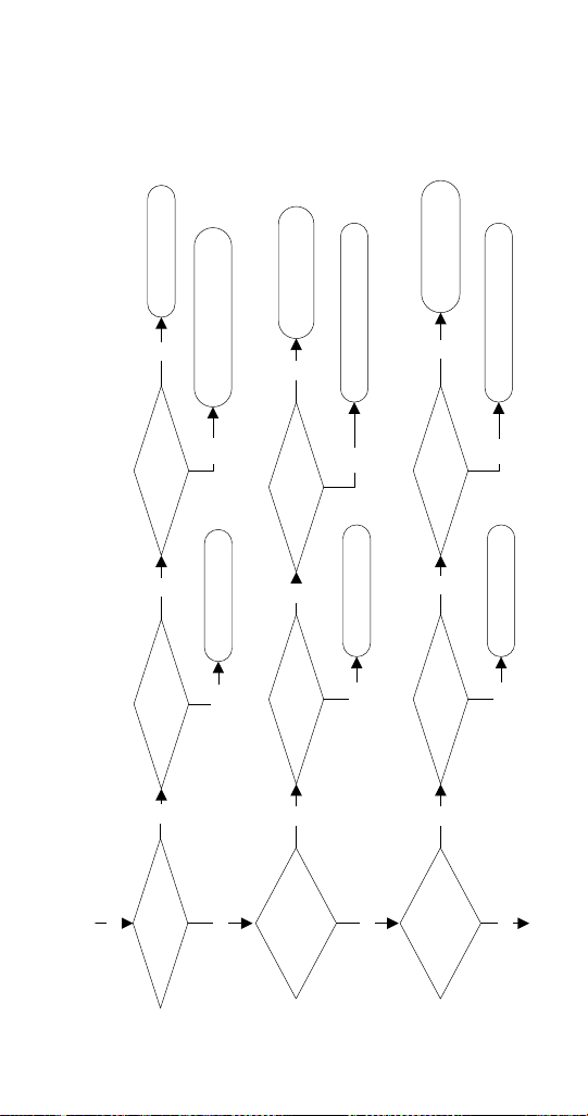
70 Part Number 000015433_03 5/20
Gear Motor Runs? NO
YES
Line Voltage To
Gear motor?
Repair WiringNo
Disconnect
Evaporator From
Gear Motor
Ice In Evaporator?
Gear Motor Runs?
Replace Gear Motor
Yes
No
Rebuild
Or
Replace Evaporator
Thaw Evaporator
Yes
Yes
No
YES
10 Minute Time
Delay Expired?
NO
Wait 10 Minutes - Do Not Install
Compressor Time Delay Jumper
Low Water Level
Switch Closed?
NO
Replace Switch or Float Assembly
YES
Yes
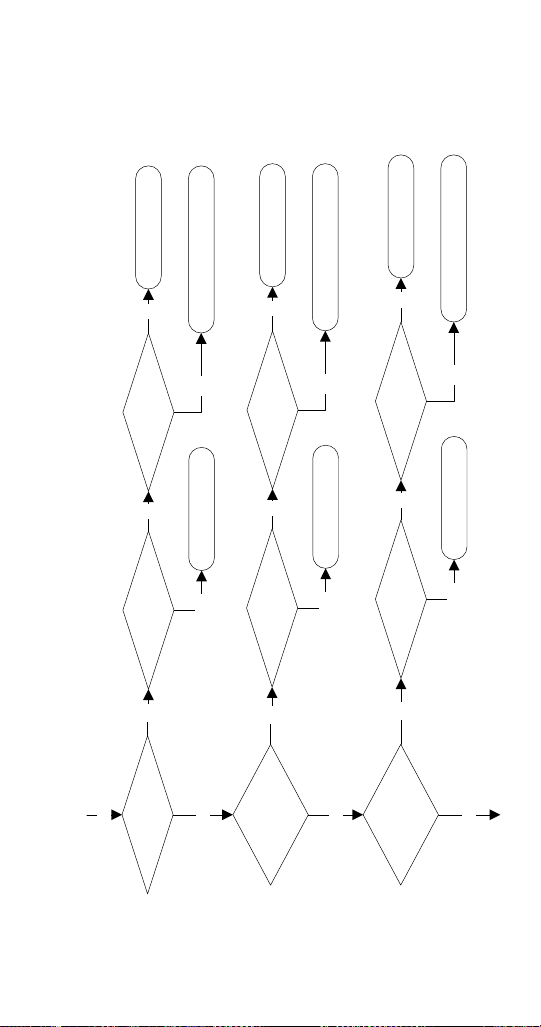
Part Number 000015433_03 5/20 71
YES
NO
Replace Relay
Line Voltage To
Left Delay Relay Coil?
NO
Repair Wiring
Replace Left Rotation
Sensor/Time Delay
No
Power To Left Time
Delay Relay Coil?
Install
Compressor Time
Delay Jumper On
Left Evaporator
Left Delay Relay
Contacts Closed?
Left Delay Relay
Contacts Closed?
Yes
No Yes
YES
NO
Replace Relay
Line Voltage To
Right Delay Relay Coil?
NO
Repair Wiring
Replace Right Rotation
Sensor/Time Delay
No
Power To Right Time
Delay Relay Coil?
Install
Compressor Time
Delay Jumper On
Right Evaporator
Right Delay Relay
Contacts Closed?
Right Delay Relay
Contacts Closed?
Yes
No Yes
YES
YES
YES
72 Part Number 000015433_03 5/20
Contactor Closed?
Line Voltage To
Compressor?
YES
YES
NO
YES
NO
Verify:
Compressor Overload is Closed
Start Components Function
Fan Cycling Control Functions
Condenser Fan Motor Functions
Water cooled only:
Water Regulating Valve Functions
Repair Wiring
Replace Contactor
Line Voltage To
Compressor Contactor
Coil?
NO Repair Wiring
Yes

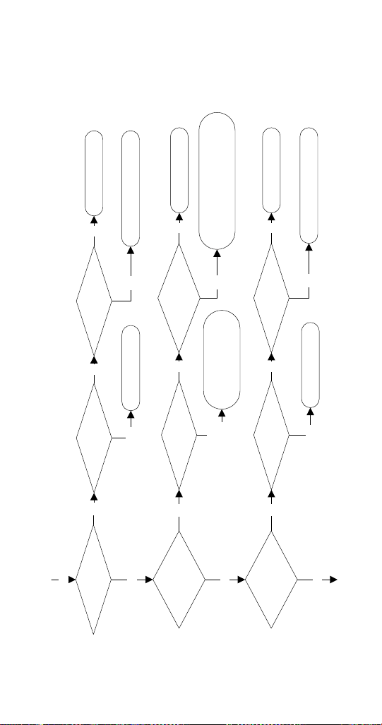
Part Number 000015433_03 5/20 73
RNF2000C/RFF2200C Troubleshooting
QUIETQUBE REMOTE AIR-COOLED MODELS WITH
REMOTE CONDENSING UNIT
Normal Operation
When the toggle switch is placed in the ON position the
following controls must be in the closed position before
the ice machine will start:
A. Bin Thermostat
B. High Pressure Cut-out Switch
C. Ice Chute Safety Switch
D. Low Pressure Switch
E. Low Water Level Switch
Placing the toggle switch in the ON position starts the gear
motor. After the rotation speed sensor verifies 8 minutes
of correct rotation the time delay ends and the liquid line
solenoid valve opens.
• When the refrigerant pressure is high enough to close
the low-pressure control the contactor coil energizes
and the compressor starts.
THE ICE MACHINE WILL CONTINUE TO MAKE ICE
UNTIL ICE CONTACTS THE BIN THERMOSTAT AND
THE LIQUID LINE SOLENOID VALVE CLOSES AND THE
REFRIGERATION SYSTEM PUMPS DOWN.
• When the refrigerant pressure is low enough to open
the low pressure control, the contactor coil is de-
energized and the compressor stops.
NOTE: The ice machine remains off until ice no longer
contacts the bin thermostat.
74 Part Number 000015433_03 5/20
Power Supplied
to Ice Machine?
Toggle Switch In
ON Position?
Move Switch To ON Position
Restore Power, Reset BreakerNO
NO
YES
Electrical Flowchart - RFF2200C QuietQube
Switch
Illuminated?
NO
YES
Replace Switch
Immediately
Trips?
YES
YES
Toggle Switch In
Off Position?
Isolate And Ohm Each
Component - Then Each
Wire If Required
NO
TRIPS
YES
Isolate And Ohm Switch
Check Wiring From Panel
YES
NO
Test Run
Part Number 000015433_03 5/20 75
Bin Thermostat
Closed?
NO
Replace Thermostat
YES
Ice Contacting
Thermostat?
Remove Ice - Allow
To Warm And Retest
Adjusting Closes
Thermostat?
Verify New Setting Cycles
Machine On/Off
YES
NO NO
YES
YES
Left Side Chute
Switch Closed?
NO
Adjust Or Replace
Actuator
Ice Contacting
Actuator?
Remove Ice And
Retest
Actuator Functions?
Replace Switch
YES
NO NO
YES
YES
Right Side Chute
Switch Closed?
NO
Adjust Or Replace
Actuator
Ice Contacting
Actuator?
Remove Ice And
Retest
Actuator Functions?
Replace Switch
YES
NO NO
YES
YES
76 Part Number 000015433_03 5/20
YES
Reservoir Full Of
Water?
NO
Restore Water
Supply / Replace
Water Inlet Valve
Power To Water
Inlet Valve?
YES
Water Level
Switch Closed?
NO NO
Repair WiringYES
Replace Switch or Float Assembly
Low Water Level
Switch Closed?
NO Replace Switch or Float Assembly
YES
Do Both Gear
Motors Run?
NO
Line Voltage To
Gear motors?
Repair WiringNO
Disconnect
Evaporator From
Gear Motor
Gear Motor
Runs?
Replace Gear Motor
YES
NO
YES
YES
Ice In
Evaporator?
Rebuild
Or
Replace Evaporator
Thaw Evaporator
YES
NO
YES
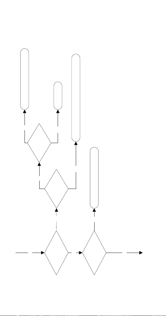
Part Number 000015433_03 5/20 77
NO
Replace Relay
Replace Right Rotation
Sensor/Time Delay
Right Delay Relay
Contacts Closed?
Right Delay Relay
Contacts Closed?
YES
Line Voltage To
Right Delay Relay Coil?
NO
Repair Wiring
NO
Power To Right Time
Delay Relay Coil?
Install
Compressor Time
Delay Jumper On
Right Evaporator
YES
YES
YES
YES
Replace Relay
NO
78 Part Number 000015433_03 5/20
YES
10 Minute Time
Delay Expired?
NO
Wait 10 Minutes - Do Not Install
Compressor Time Delay Jumper
Yes
YES
NO
Replace Relay
NO
Repair Wiring
Replace Left Rotation
Sensor/Time Delay
No
Power To Left Time
Delay Relay Coil?
Install
Compressor Time
Delay Jumper On
Left Evaporator
Left Delay Relay
Contacts Closed?
Left Delay Relay
Contacts Closed?
Yes
No Yes
YES
Line Voltage To
Left Delay Relay Coil?
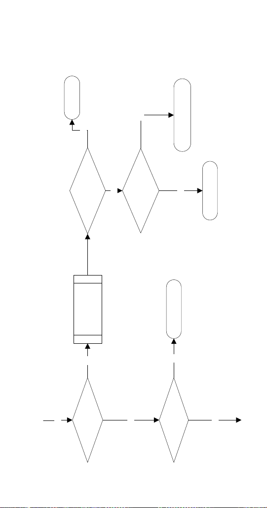
Part Number 000015433_03 5/20 79
Replace Relay
Line Voltage To
Compressor
Contactor Coil?
YES
Low Pressure
Control Closed?
Line Voltage At
Liquid Line Solenoid
Valve?
NO
NO
YES
Verify:
Refrigerant Pressure is Higher Than LPCO Cut-
in Both Shut-off Valves are Open Repair/
Replace Liquid Line Solenoid Locate and Repair
Refrigerant Leak
Replace LPCO Switch
YES
High Pressure
Control Closed?
Resets?
Replace HPCO
Clean Condenser, Check
Fan Motor Check Fan
Cycle Control
Refrigerant Pressure
Above Cut-out?
Resets
&
Trips
NO NO
YES
NO
NO
Clean Condenser,
Check Fan Motor,
Check Fan Cycle Control &
Refrigeration System
YES
YES
Repair Wiring
Part Number 000015433_03 5/20 81
Refrigeration Troubleshooting
CAPILLARY TUBE MODELS
If the gear motor and/or compressor are not energized refer to Electrical Troubleshooting
Refer to Operational Pressure Charts for normal pressures and temperatures
Low on Refrigerant Overcharge of Refrigerant Non Condensible
in System
Restricted Capillary Tube
Discharge Pressure Low High High Low
Suction Pressure Low High High Low
Evaporator Inlet Temperature Normal Low High Low
Evaporator Outlet
Temperature
High Normal High Low
Compressor Discharge Line
Temperature
Normal Range =
> 165° @ 70° - 210° @ 110°
> 74°C @ 21°C - 99°C @ 43°C)
High
Increases with
run time
Normal High
Increases with
run time
High
Increases with
run time
82 Part Number 000015433_03 5/20
THERMOSTATIC EXPANSION VALVE MODELS
If the gear motor and/or compressor are not energized refer to Electrical Troubleshooting
Refer to Operational Pressure Charts for normal pressures and temperatures
Low on
Refrigerant
Overcharge of
Refrigerant
Non Condensible
In System
Liquid Line Restriction,
Suction Line Restriction,
Or Expansion Valve
Starving
Flooding Expansion Valve
or Loose Sensing Bulb
(when used)
Discharge Pressure Low High High Low High
Suction Pressure Low High High Low High
Evaporator Inlet
Temperature
Normal Normal or Low High Normal Normal or High
Evaporator Outlet
Temperature
High Normal High High > 12° Differential
between Inlet and Outlet
< 10° Differential between
Inlet and Outlet
Discharge Line
Temperature
High Normal High
Increases With
Run Time
High
Increases With
Run Time
Low
Decreases With Run Time
Part Number 000015433_03 5/20 83
BIN THERMOSTAT
Model Setting Cut-Out Cut-In
UFF0200 / UNF0200
UNF0300 / UFF0350
5
37°F ±1
3°C ±.1
43°F ±1
6°C ±.1
RFF0320 / RFF0620
RNF0620 / RNF1100
RNF1020C / RFF1300
RFF1220C / RNF2000C
RFF2200C / RFF2500
3
35°F ±1
1.6°C ±.1
41°F ±1
5.0°C ±.1
LOW TEMPERATURE THERMOSTAT
EVAPORATOR SAFETY THERMOSTAT
Model Setting Cut-Out Cut-In
UFF0200 / UNF0300
5
-1°F ±1
-17.2°C ±.1
39°F ±1
4°C ±.1
UNF0200 / UNF0300
RFF0320
6
-3°F ±1
-19.5°C ±.1
39°F±.1
4°C ±.1
RNF0320 / UFF0350
7
-8°F ±.1
-22°C ±.1
39°F±.1
4°C ±.1
Component Specifications

84 Part Number 000015433_03 5/20
HIGH PRESSURE CUTOUT (HPCO) CONTROL
Model Cut-Out Cut-In
RNF0320 / RFF0620
RFF1300 / RNF0320
RNF0620 / RNF1100
325 psig ±10
(2250 kPa ±69)
22.5 bar ±.69
200 psig ±10
(1379 kPa ±69)
13.79 bar ±.69
Auto Reset
RFF2500
435 psig ±10
(3000 kPa ±69)
30 bar ±.69
Manual Reset
RNF1020C / RCUF1000
RFF1220C / RCUF1200
RNF2000C / RCUF2200
RFF2200C / RCUF2200
450 psig ±10
(3100 kPa ±69)
31 bar ±.69
300 psig ±10
(2068 kPa ±69)
20 bar ±20.68
Auto Reset

Part Number 000015433_03 5/20 85
ROTATION SENSOR
RFF0620 / RNF0620 / RNF1100 / RNF1020C / RFF1300
RNF2000C / RFF2500
Light Definition
Yellow Blinking Time Delay Period
Yellow Solid Normal Operation Sensing
Red Blinking 2
Flashes Per Second
Time Delay Period - First 1 To 7 Faults
Red Solid Lockout - 8 Consecutive Faults Due To A
Speed Fault
Remove/Restore Power To Reset
Red Blinking Slowly Lockout - 8 Consecutive Faults Due To A
Short Circuit
Operation:
1. At start up, the sensor starts an 8 minute compressor
time delay period.
2. After 8 minutes the sensor energizes the compressor
contactor and ignores rotation for 20 seconds.
3. After 8-minutes, 20 seconds the auger rotation
must not fall below 4 rpm or exceed 13 rpm; normal
rotation is 9-10 RPM. When the auger rotation is
less than 4 rpm or more than 13 rpm the sensor
de-energizes the compressor contactor, starts an 8
minute time delay period and flashes the red led.
When the 8 minute delay period ends the compressor
will restart.
4. If the rotation sensor detects 8 consecutive RPM out
of range failures the sensor locks out the compressor
contactor and energizes the red led. The rotation
sensor must be reset by cycling power off/on.
NOTE: Verify all electrical connections are secure and free
of corrosion whenever rotation sensor lockouts exist.
86 Part Number 000015433_03 5/20
LOW PRESSURE CUTOUT (LPCO) CONTROL
Model Cut-Out Cut-In
UFF0200 / RNF0320
RNF0620 / RFF0620
RNF1100 / RFF1300
RFF2200C / RCUF2200
7 psig ±2
(.5 bar ±.2)
36 psig ±2
(2.5 bar ±.2)
RFF2500
12 psig ±2
(.8 bar ±.2)
Manual Reset
FAN CYCLE CONTROL
Model Cut-Out (Open) Cut-In (Close)
UFF0200 / RNF0320
RFF0320 / UFF0350
RNF0620 / RFF0620
RFF1300 / RFF2500
200 ±5
(15.17 bar ±.34)
250 ±5
(17.23 bar ±.34)
UNF0200 / UNF0300
RNF0320 / UFF0350
RFF0620 / RNF1100
RFF1300 / RFF2500
225 ±5
(15.51 bar ±.34)
275 ±5
(18.96 bar ±.34)
Part Number 000015433_03 5/20 87
TOTAL SYSTEM REFRIGERANT CHARGE
This information is for reference only. Model/Serial plate
information overrides information listed in this table.
Model Refrigerant Charge
Flake Models
UFF0200A 9.4 oz / 265 g
UFF0350A 11.25 oz / 320 g
RFF0320A 13.6 oz / 395 g
RFF0620A 20.8 oz / 590 g
RFF0620W 16.9 oz / 480 g
RFF1300A 21.9 oz / 620 g
RFF1220C 156 oz / 4.42 kg
RFF2200C 240 oz / 6.08 kg
RFF2500A 67 oz / 1900 g
Nugget Models
UNF0200A 8.5 oz / 240 g
UNF0300A 14.8 oz / 420 g
RNF0620A 18.34 oz / 520 g
RNF0620W 16.9 oz / 480 g
RNF1100A 23.3 oz / 660 g
RNF1100W 18.0 oz / 510 g
RNF1020C 160.0 oz / 4.54 kg
RNF2000C 240.0 oz / 6.08 kg
Model Additional refrigerant required for
51’ to 100’ (15.5 to 30.5 m) line sets
RFF1220C 0 lbs 0 kg
RFF2200C 0 lbs 0 kg
RNF1020C 2 lbs 907g
RNF2000C 0 lbs 0 kg
88 Part Number 000015433_03 5/20
FILTER-DRIERS
The size of the filter-drier is important. The refrigerant
charge is critical. Using an improperly sized filter-drier
will cause the ice machine to be improperly charged with
refrigerant.
Important
Driers are covered as a warranty part. The drier must be
replaced any time the system is opened for repairs.
SUCTION CLEANUP FILTER-DRIER
Contaminated systems must have a suction line filter-drier
installed to remove contaminations. An access valve must
be installed on the inlet side of the suction filter to allow
pressure drop readings to be obtained.
Suction Line Clean-Up Filter
Model Drier Size End
Connection
Size
All Models UK-165S 5/8 in.

Part Number 000015433_03 5/20 89
Ice Production & Refrigerant Pressure
These charts are used as guidelines to verify correct ice
machine operation.
Accurate collection of data is essential to obtain the
correct diagnosis.
• Zero out manifold gauge set before obtaining pressure
readings to avoid mis-diagnosis.
• Discharge and suction pressure are highest at the
beginning of the cycle. Allow system to stabilize for a
minimum of 10 minutes, then verify the pressures are
within the range indicated.
• Water temperature will affect suction and discharge
pressure - 50°F (10°C) water temperature will result
in pressures on the lower end of the ranges specified.
90°F (32°C) water temperatures will result in pressures
on the upper end of the range specified.
Charts
90 Part Number 000015433_03 5/20
Flake Models
UFF200A
SELF CONTAINED AIR-COOLED
Characteristics vary depending on operating conditions.
ICE PRODUCTION
Air Temperature
Water Temperature
24 hour
Ice Production
70°F/50°F
21°C/10°C
257 lbs
116 kgs
90°F/70°F
32°C/21°C
198 lbs
90 kgs
OPERATING PRESSURES PSIG & kPa
Air Temperature
Entering
Condenser
Freeze Cycle
Discharge
Pressure
Suction
Pressure
70°F PSIG
21°C kPa
220-250
1517-1724
38-40
262-276
90°F PSIG
32°C kPa
300-320
2068-2206
45-51
310-352
110°F PSIG
43°C kPa
360-390
2482-2689
49-55
338-379
Part Number 000015433_03 5/20 91
RFF0320A
SELF CONTAINED AIR-COOLED
Characteristics vary depending on operating conditions.
ICE PRODUCTION
Air Temperature
Water Temperature
24 hour
Ice Production
70°F/50°F
21°C/10°C
370 lbs
168 kgs
90°F/70°F
32°C/21°C
286 lbs
130 kgs
OPERATING PRESSURES PSIG & kPa
Air Temperature
Entering
Condenser
Freeze Cycle
Discharge
Pressure
Suction
Pressure
70°F PSIG
21°C kPa
210-255
1448-1758
29-33
200-228
90°F PSIG
32°C kPa
280-325
1930-2241
30-35
207-241
110°F PSIG
43°C kPa
360-395
2482-2723
33-36
228-248
92 Part Number 000015433_03 5/20
UFF0350A
SELF CONTAINED AIR-COOLED
Characteristics vary depending on operating conditions.
ICE PRODUCTION
Air Temperature
Water Temperature
24 hour
Ice Production
70°F/50°F
21°C/10°C
398 lbs
181 kgs
90°F/70°F
32°C/21°C
328 lbs
149 kgs
OPERATING PRESSURES PSIG & kPa
Air Temperature
Entering
Condenser
Freeze Cycle
Discharge
Pressure
Suction
Pressure
70°F PSIG
21°C kPa
225-270
1551-1862
26-30
179-207
90°F PSIG
32°C kPa
273-315
1882-2172
27-32
186-221
110°F PSIG
43°C kPa
348-380
2399-2620
33-41
228-283
Part Number 000015433_03 5/20 93
RFF0620A
SELF CONTAINED AIR-COOLED
Characteristics vary depending on operating conditions.
ICE PRODUCTION
Air Temperature
Water Temperature
24 hour
Ice Production
70°F/50°F
21°C/10°C
747 lbs
339 kgs
90°F/70°F
32°C/21°C
506 lbs
230kgs
OPERATING PRESSURES PSIG & kPa
Air Temperature
Entering
Condenser
Freeze Cycle
Discharge
Pressure
Suction
Pressure
70°F PSIG
21°C kPa
240-265
1655-1827
33-35
228-241
90°F PSIG
32°C kPa
280-300
1930-2068
34-40
235-276
110°F PSIG
43°C kPa
340-370
2344-2551
40-46
275-318
94 Part Number 000015433_03 5/20
RFF0620W
SELF CONTAINED WATER-COOLED
Characteristics vary depending on operating conditions.
ICE PRODUCTION
Air Temperature
Water Temperature
24 hour
Ice Production
70°F/50°F
21°C/10°C
740 lbs
335 kgs
90°F/70°F
32°C/21°C
596 lbs
270 kgs
OPERATING PRESSURES PSIG & kPa
Air Temperature
Entering
Condenser
Freeze Cycle
Discharge
Pressure
Suction
Pressure
70°F PSIG
21°C kPa
270-280
1724-1793
32-35
221-241
90°F PSIG
32°C kPa
270-285
1758-1827
33-36
228-248
110°F PSIG
43°C kPa
275-290
1827-1896
35-37
241-255
Water regulating valve set to 230 psi (1586 kPa)

Part Number 000015433_03 5/20 95
RFF1220C WITH RCUF1200
QUIETQUBE REMOTE CONDENSER AIR COOLED
Characteristics vary depending on operating conditions
ICE PRODUCTION
Air Temperature
Water Temperature
24 Hour
Ice Production
-20°F/50°F
-29°C/10°C
1413 lbs
641 kgs
70°F/50°F
21°C/10°C
1092 lbs
495 kgs
90°F/70°F
32°C/21°C
958 lbs
435 kgs
120°F/70°F
49°C/21°C
603 lbs
274 kgs
OPERATING PRESSURES PSIG & kPa
Air Temperature
Entering
Condenser
°F/°C
Freeze Cycle
Discharge Pressure Suction Pressure
50°F PSIG
10°C kPa
185-200
1276-1379
23-28
159-193
70°F PSIG
21°C kPa
225-255
1551-1758
30-35
207-241
80°F PSIG
27°C kPa
230-280
1586-1931
31-36
214-248
90°F PSIG
32°C kPa
243-305
1675-2103
33-38
228-262
120°F PSIG
49°C kPa
355-400
2448-2758
38-43
262-296
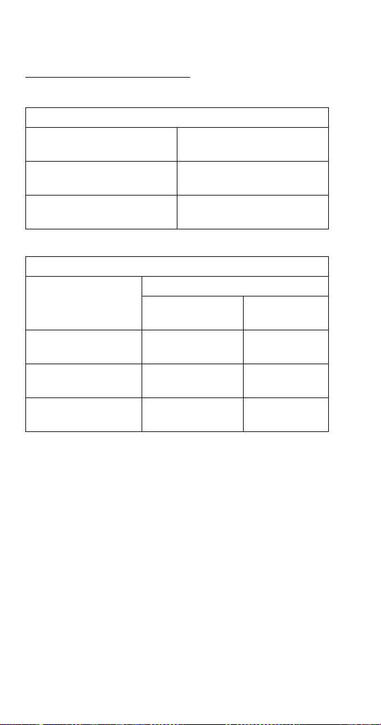
96 Part Number 000015433_03 5/20
RFF1300A
SELF CONTAINED AIR-COOLED
Characteristics vary depending on operating conditions.
ICE PRODUCTION
Air Temperature
Water Temperature
24 hour
Ice Production
70°F/50°F
21°C/10°C
1264 lbs
573 kgs
90°F/70°F
32°C/21°C
950 lbs
431 kgs
OPERATING PRESSURES PSIG & kPa
Air Temperature
Entering
Condenser
Freeze Cycle
Discharge
Pressure
Suction
Pressure
70°F PSIG
21°C kPa
240-280
1655-1930
30-34
207-234
90°F PSIG
32°C kPa
300-350
2068-2413
32-37
221-255
110°F PSIG
43°C kPa
380-425
2620-2930
35-39
241-269
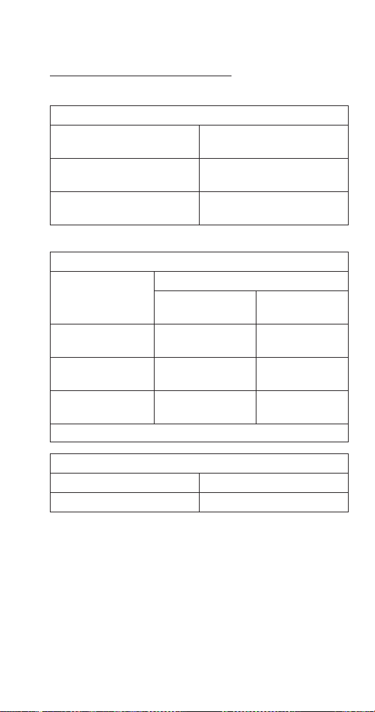
Part Number 000015433_03 5/20 97
RFF1300W
SELF CONTAINED WATER-COOLED
Characteristics vary depending on operating conditions.
ICE PRODUCTION
Air Temperature
Water Temperature
24 hour
Ice Production
70°F/50°F
21°C/10°C
1365 lbs
619 kgs
90°F/70°F
32°C/21°C
1116 lbs
506 kgs
OPERATING PRESSURES PSIG & kPa
Air Temperature
Entering
Condenser
Freeze Cycle
Discharge
Pressure
Suction
Pressure
70°F PSIG
21°C kPa
230-250
1586-1724
29-32
200-221
90°F PSIG
32°C kPa
230-250
1586-1724
30-32
207-221
110°F PSIG
43°C kPa
230-250
1586-1724
30-32
207-221
Water regulating valve set to maintain 240 psi (1655 kPa)
Condenser Water Consumption @ 90°F/70°F
116 Gallons/100 lbs. of Ice
439 Liters/45 kgs. of Ice
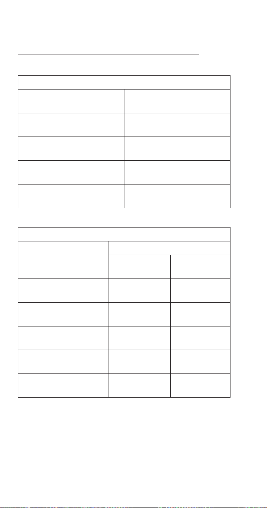
98 Part Number 000015433_03 5/20
RFF2200C WITH RCUF2200
QUIETQUBE REMOTE CONDENSER AIR COOLED
Characteristics vary depending on operating conditions
ICE PRODUCTION
Air Temperature
Water Temperature
24 Hour
Ice Production
-20°F/50°F
-29°C/10°C
2403 lbs
1090 kgs
70°F/50°F
21°C/10°C
2063 lbs
936 kgs
90°F/70°F
32°C/21°C
1702 lbs
772 kgs
120°F/70°F
49°C/21°C
1073 lbs
487 kgs
OPERATING PRESSURES PSIG& kPa
Air Temperature Around
Ice Machine
°F/°C
Freeze Cycle
Discharge
Pressure
Suction
Pressure
50°F PSIG
16°C kPa
175-200
1207-1379
26-31
176-214
70°F PSIG
21°C kPa
220-250
1517-1724
31-36
214-248
80°F PSIG
27°C kPa
225-275
1551-1896
32-37
221-255
90°F PSIG
32°C kPa
250-310
1724-2137
33-38
228-262
120°F PSIG
49°C kPa
365-410
2517-2827
38-43
262-296
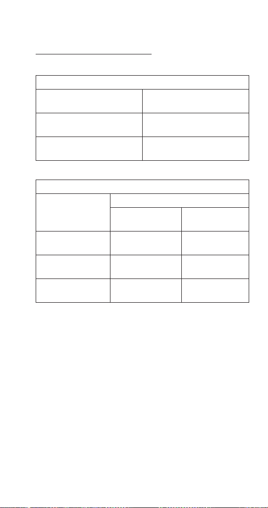
Part Number 000015433_03 5/20 99
RFF2500A
SELF CONTAINED AIR-COOLED
Characteristics vary depending on operating conditions.
ICE PRODUCTION
Air Temperature
Water Temperature
24 hour
Ice Production
70°F/50°F
21°C/10°C
2301 lbs
1044 kgs
90°F/70°F
32°C/21°C
1665 lbs
755 kgs
OPERATING PRESSURES PSIG & kPa
Air Temperature
Entering
Condenser
Freeze Cycle
Discharge
Pressure
Suction
Pressure
70°F PSIG
21°C kPa
290-310
1999-2137
35-38
241-262
90°F PSIG
32°C kPa
350-380
2413-2620
38-43
262-296
110°F PSIG
43°C kPa
410-430
2827-2965
43-49
296-338
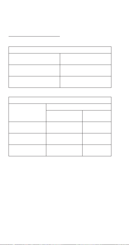
100 Part Number 000015433_03 5/20
Nugget Models
UNF0200A
SELF STORAGE AIR-COOLED
Characteristics vary depending on operating conditions.
ICE PRODUCTION
Air Temperature
Water Temperature
24 hour
Ice Production
70°F/50°F
21°C/10°C
231 lbs
97 kgs
90°F/70°F
32°C/21°C
164 lbs
74 kgs
OPERATING PRESSURES PSIG & kPa
Air Temperature
Entering
Condenser
Freeze Cycle
Discharge
Pressure
Suction
Pressure
70°F PSIG
21°C kPa
220-250
1517-1724
38-40
262-276
90°F PSIG
32°C kPa
300-320
2068-2206
45-51
310-352
110°F PSIG
43°C kPa
360-390
2482-2689
49-55
338-379
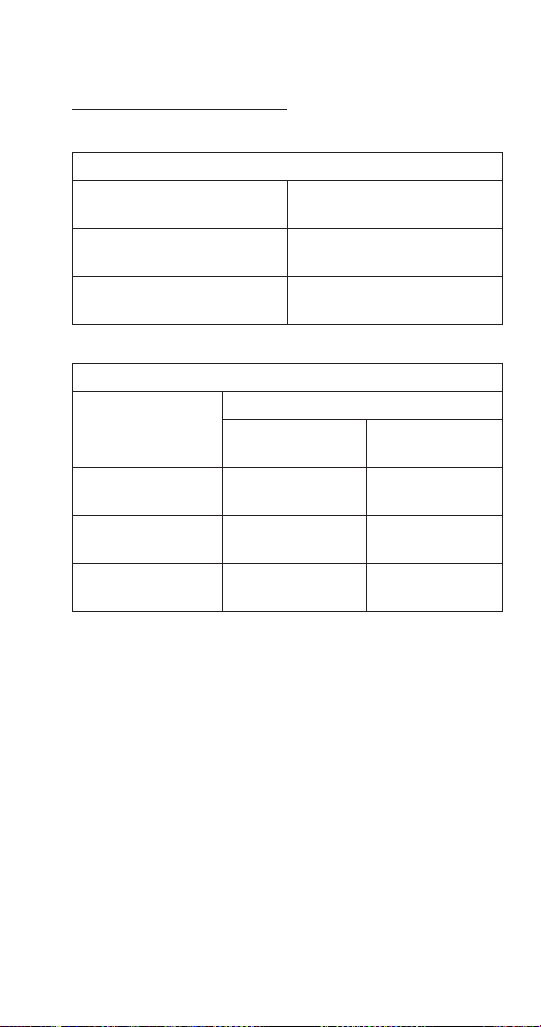
Part Number 000015433_03 5/20 101
UNF0300A
SELF STORAGE AIR-COOLED
Characteristics vary depending on operating conditions.
ICE PRODUCTION
Air Temperature
Water Temperature
24 hour
Ice Production
70°F/50°F
21°C/10°C
330 lbs
150 kgs
90°F/70°F
32°C/21°C
275 lbs
125 kgs
OPERATING PRESSURES PSIG & kPa
Air Temperature
Entering
Condenser
Freeze Cycle
Discharge
Pressure
Suction
Pressure
70°F PSIG
21°C kPa
243-270
1675-1862
31-36
214-248
90°F PSIG
32°C kPa
273-315
1882-2172
34-39
234-269
110°F PSIG
43°C kPa
348-380
2399-2620
38-43
262-296
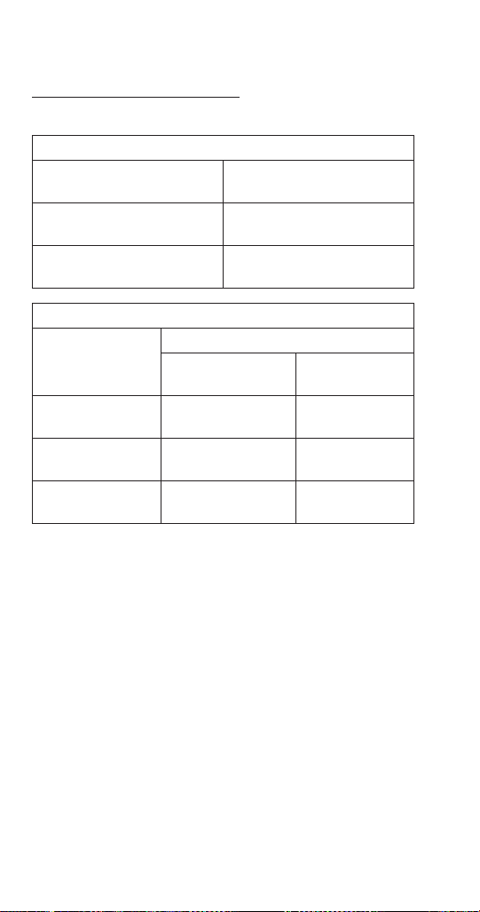
102 Part Number 000015433_03 5/20
RNF0320A
SELF CONTAINED AIR-COOLED
Characteristics vary depending on operating conditions.
ICE PRODUCTION
Air Temperature
Water Temperature
24 hour
Ice Production
70°F/50°F
21°C/10°C
308 lbs
140 kgs
90°F/70°F
32°C/21°C
236 lbs
107 kgs
OPERATING PRESSURES PSIG & kPa
Air Temperature
Entering
Condenser
Freeze Cycle
Discharge
Pressure
Suction
Pressure
70°F PSIG
21°C kPa
210-255
1448-1758
28-32
193-220
90°F PSIG
32°C kPa
280-320
1931-2206
30-33
207-228
110°F PSIG
43°C kPa
370-405
2551-2792
32-36
220-248
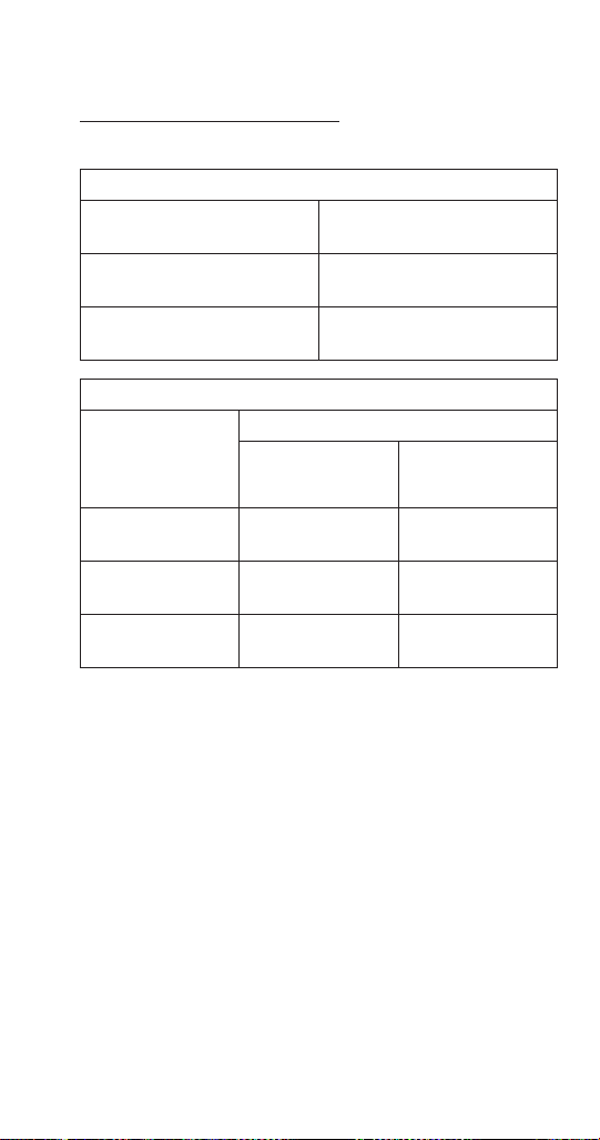
Part Number 000015433_03 5/20 103
RNF0620A
SELF CONTAINED AIR-COOLED
Characteristics vary depending on operating conditions.
ICE PRODUCTION
Air Temperature
Water Temperature
24 Hour
Ice Production
70°F/50°F
21°C/10°C
591 lbs
268 kgs
90°F/70°F
32°C/21°C
451 lbs
204 kgs
OPERATING PRESSURES PSIG & kPa
Air Temperature
Around Ice
Machine
°F/°C
Freeze Cycle
Discharge
Pressure
Suction
Pressure
70°F PSIG
21°C kPa
215-225
1483-1551
27-29
186-200
90°F PSIG
32°C kPa
280-290
1931-2000
29-31
200-214
110°F PSIG
43°C kPa
360-370
2482-2551
32-34
221-234
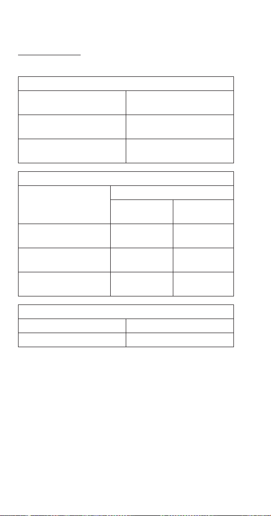
104 Part Number 000015433_03 5/20
RNF0620W
WATER-COOLED
Characteristics vary depending on operating conditions.
ICE PRODUCTION
Air Temperature
Water Temperature
24 Hour
Ice Production
70°F/50°F
21°C/10°C
613 lbs
278 kgs
90°F/70°F
32°C/21°C
508 lbs
230 kgs
OPERATING PRESSURES PSIG & kPa
Air Temperature Around
Ice Machine
°F/°C
Freeze Cycle
Discharge
Pressure
Suction
Pressure
70°F PSIG
21°C kPa
235-245
1670-1689
27-29
186-199
90°F PSIG
32°C kPa
235-245
1670-1689
27-29
186-199
110°F PSIG
43°C kPa
240-260
1655-1793
28-32
193-220
Condenser Water Consumption @ 89°F/70°F
109 Gallons/100 lbs. of Ice
413 Liters/45 kgs. of Ice
Water regulating valve set to maintain 240 PSIG - 1655 kPa
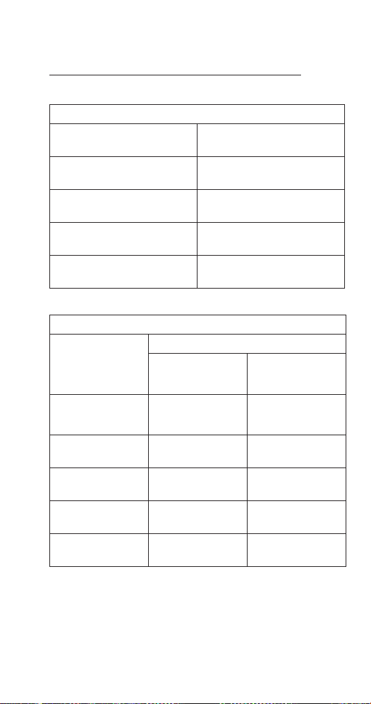
Part Number 000015433_03 5/20 105
RNF1020C WITH RCUF1000
QUIETQUBE REMOTE CONDENSER AIR COOLED
Characteristics vary depending on operating conditions
ICE PRODUCTION
Air Temperature
Water Temperature
24 Hour
Ice Production
-20°F/50°F
-29°C/10°C
1282 lbs
582 kgs
70°F/50°F
21°C/10°C
1116 lbs
506 kgs
90°F/70°F
32°C/21°C
900 lbs
408 kgs
110°F/90°F
43°C/32°C
693 lbs
314 kgs
OPERATING PRESSURES PSIG & kPa
Air Temperature
Around Ice
Machine
°F/°C
Freeze Cycle
Discharge Pressure Suction Pressure
60°F PSIG
16°C kPa
240-250
1655-1724
33-35
227-241
70°F PSIG
21°C kPa
245-265
1689-1827
35-38
241-262
80°F PSIG
27°C kPa
245-270
1689-1862
36-39
248-269
90°F PSIG
32°C kPa
250-270
1724-1862
37-40
255-276
110°F PSIG
43°C kPa
360-400
2482-2758
45-49
310-338
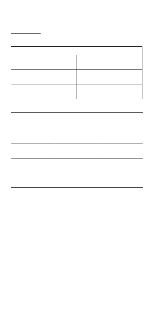
106 Part Number 000015433_03 5/20
RNF1100A
AIR-COOLED
Characteristics vary depending on operating conditions.
ICE PRODUCTION
Air Temperature
Water Temperature
24 Hour
Ice Production
70°F/50°F
21°C/10°C
1078 lbs
489 kgs
90°F/70°F
32°C/21°C
825 lbs
374 kgs
OPERATING PRESSURES PSIG & kPa
Air Temperature
Around Ice
Machine
°F/°C
Freeze Cycle
Discharge
Pressure
Suction
Pressure
70°F PSIG
21°C kPa
220-240
1517-1655
30-32
207-221
90°F PSIG
32°C kPa
275-310
1896-2137
33-35
228-241
110°F PSIG
43°C kPa
370-390
2551-2689
38-40
262-276
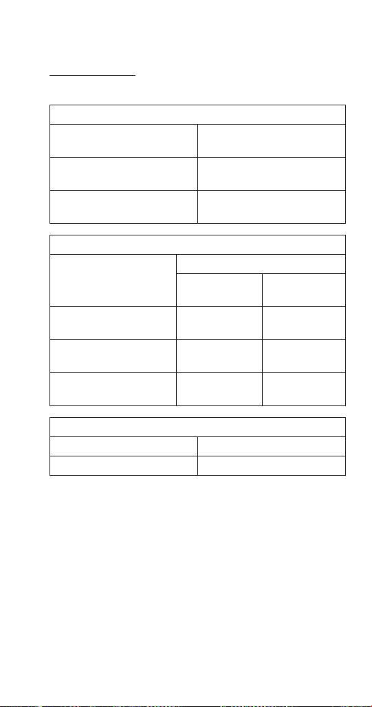
Part Number 000015433_03 5/20 107
RNF1100W
WATER-COOLED
Characteristics vary depending on operating conditions.
ICE PRODUCTION
Air Temperature
Water Temperature
24 Hour
Ice Production
70°F/50°F
21°C/10°C
1158 lbs
525 kgs
90°F/70°F
32°C/21°C
960 lbs
435 kgs
OPERATING PRESSURES PSIG & kPa
Air Temperature Around
Ice Machine
°F/°C
Freeze Cycle
Discharge
Pressure
Suction
Pressure
70°F PSIG
21°C kPa
235-245
1670-1689
29-31
200-214
90°F PSIG
32°C kPa
235-245
1670-1689
29-31
200-214
110°F PSIG
43°C kPa
240-260
1655-1793
30-36
207-248
Condenser Water Consumption @ 80°F/70°F
131 Gallons/100 lbs. of Ice
496 Liters/45 kgs. of Ice
Water regulating valve set to maintain 240 PSIG - 1655 kPa.
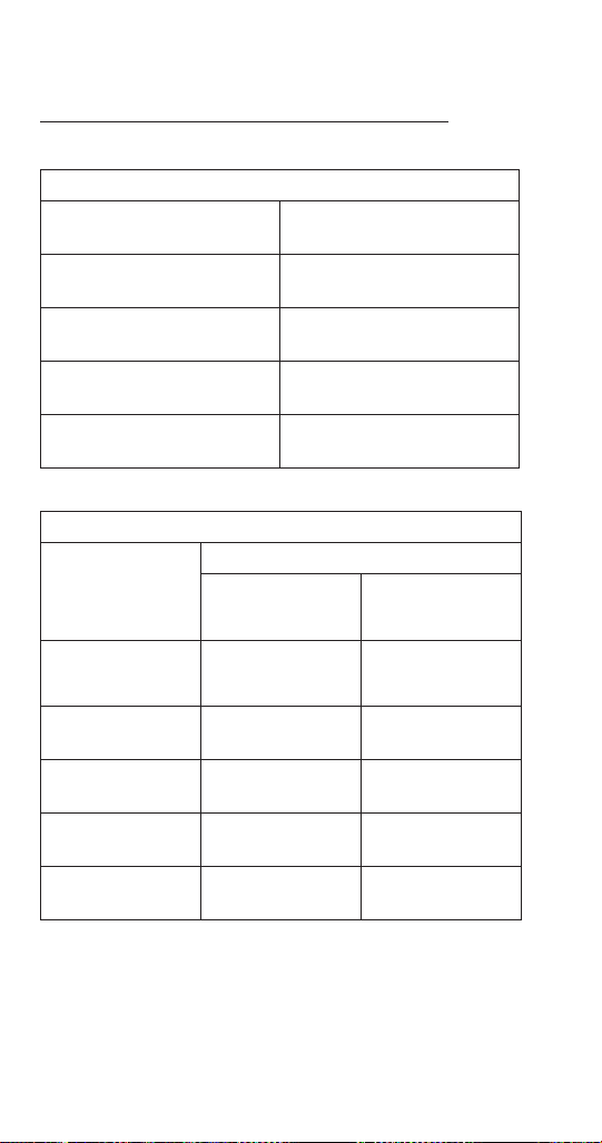
108 Part Number 000015433_03 5/20
RNF2000C
QUIETQUBE REMOTE CONDENSER AIR COOLED
Characteristics vary depending on operating conditions
ICE PRODUCTION
Air Temperature
Water Temperature
24 Hour
Ice Production
-20°F/50°F
-29°C/10°C
2300 lbs
1043 kgs
70°F/50°F
21°C/10°C
1915 lbs
869 kgs
90°F/70°F
32°C/21°C
1476 lbs
670 kgs
120°F/70°F
49°C/21°C
810 lbs
367 kgs
OPERATING PRESSURES PSIG & kPa
Air Temperature
Around Ice
Machine
°F/°C
Freeze Cycle
Discharge Pressure Suction Pressure
-20°F/50°F
-29°C/10°C
160-180 24-34
70°F PSIG
21°C kPa
200-215 28-36
80°F PSIG
27°C kPa
225-250 30-37
90°F PSIG
32°C kPa
250-270 32-38
120°F PSIG
49°C kPa
380-400 40-45

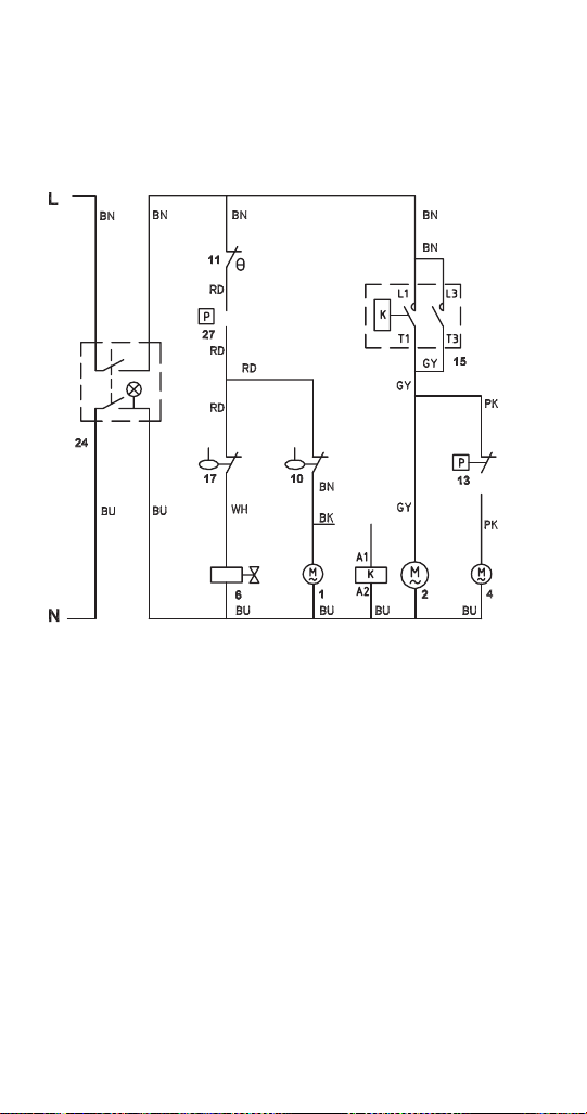
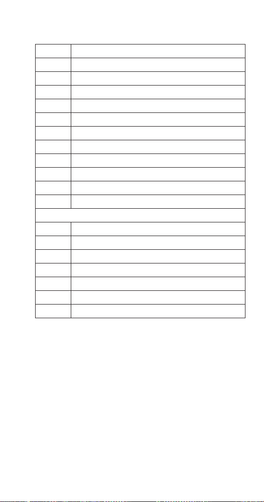
Part Number 000015433_03 5/20 111
Wiring Diagram Legend UFF0200A/UFF0350A Air-cooled
1 Gear motor
2 Compressor
4 Condenser fan motor
6 Water inlet valve
10 Low water level safety
11 Bin thermostat
12 High temperature limit (snap disc)
13 Fan cycle control
15 Contactor
17 Water level switch
24 On/Off switch
27 Low pressure safety switch
Wire Color Designation
WH White
BU Blue
GY Grey
BN Brown
BK Black
RD Red
PK Pink
Part Number 000015433_03 5/20 113
Wiring Diagram Legend RFF0320A/RFF0620A Air-cooled
1 Gear motor
2 Compressor
4 Fan motor
6 Water inlet valve
10 Low water level switch
11 Bin thermostat
13 Fan cycle control
15 Contactor
17 Water level switch
18 Chute safety switch
19 High pressure safety switch
24 On/Off switch
27 Low pressure safety switch
30 Rotation sensor
35 Compressor time delay by-pass
Wire Color Designation
WH White
BU Blue
GY Grey
BN Brown
BK Black
RD Red
PK Pink
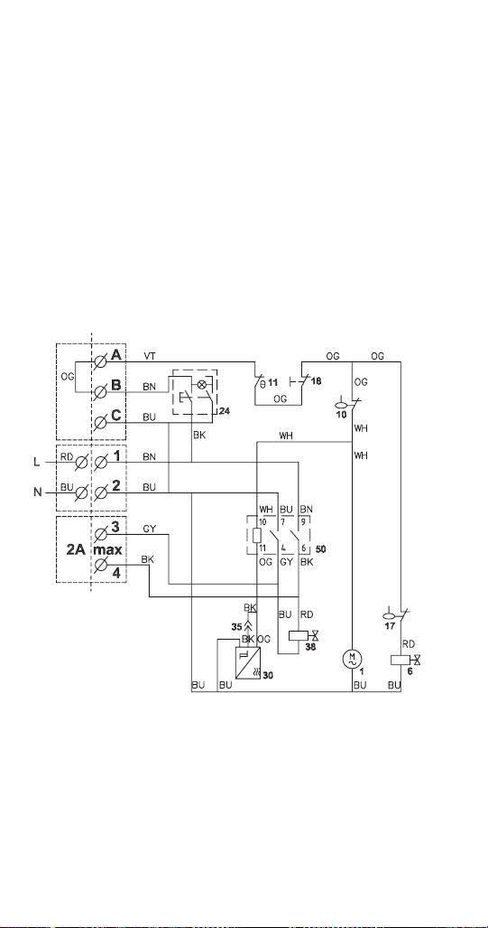
114 Part Number 000015433_03 5/20
RFF1220C QUIETQUBE HEAD SECTION
Refer to Nameplate for Voltage Rating
Connections
• A, B, & C connect to a remote panel when used -
Jumper must be removed when remote panel is used
• 1 & 2 connect to line voltage
• 3 & 4 energizes remote condensing unit (RCU)
refrigeration - 2 Amp max
• 5 terminal or junction block located on top of the
junction box.
• 6 junction box at rear of ice machine
See page 140 for condensing unit wiring diagram.
241151_03
6
5
Part Number 000015433_03 5/20 115
Wiring Diagram Legend RFF1220C Head Section
1 Gear motor
6 Water inlet valve
10 Low water level safety
11 Bin thermostat
17 Water level switch
18 Ice chute safety switch
24 On/Off switch
30 Rotation sensor
35 Compressor time delay by-pass
38 Solenoid valve
50 Relay
Wire Color Designation
WH White
BU Blue
GY Grey
BN Brown
BK Black
RD Red
VT Violet
OG Orange
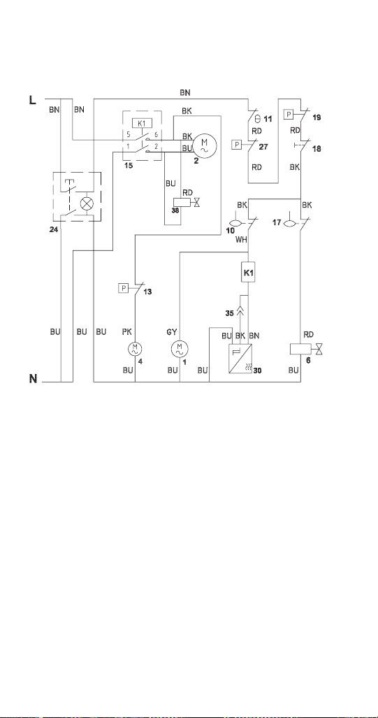

Part Number 000015433_03 5/20 117
Wiring Diagram Legend RFF1300A Air-cooled
1 Gear motor
2 Compressor
4 Fan motor
6 Water inlet valve
10 Low water level switch
11 Bin thermostat
13 Fan cycle control
15 Contactor
17 Water level switch
18 Chute safety switch
19 High pressure safety switch
24 On/Off switch
27 Low pressure safety switch
30 Rotation sensor
35 Compressor time delay bypass
38 Solenoid valve
Wire Color Designation
GY Grey
WH White
BU Blue
BN Brown
BK Black
RD Red
PH Pink
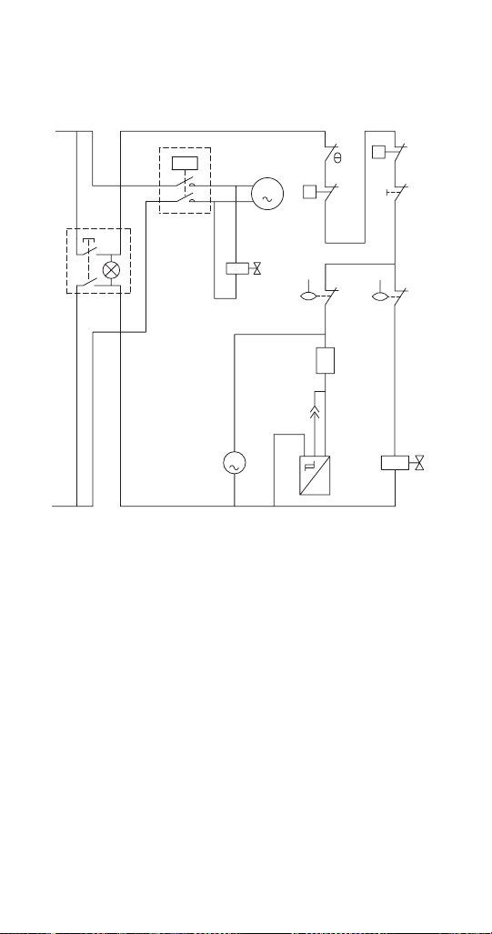

Part Number 000015433_03 5/20 119
Wiring Diagram Legend RFF1300W Water-cooled
1 Gear motor
2 Compressor
6 Water inlet valve
10 Low water level switch
11 Bin thermostat
15 Contactor
17 Water level switch
18 Chute safety switch
19 High pressure safety switch
24 On/Off switch
27 Low pressure safety switch
30 Rotation sensor
35 Compressor time delay bypass
38 Solenoid valve
Wire Color Designation
GY Grey
WH White
BU Blue
BN Brown
BK Black
RD Red
PH Pink
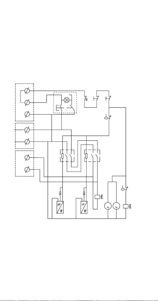
120 Part Number 000015433_03 5/20
RNF2000C QUIETQUBE HEAD SECTION
Refer to Nameplate for Voltage Rating
Connections
• A, B, & C connect to a remote panel when used -
Jumper must be removed when remote panel is used
• 1 & 2 connect to line voltage
• 3 & 4 energizes remote condensing unit (RCU)
refrigeration - 2 Amp max
See page 140 for condensing unit wiring diagram.
A
RD
BN
GY
WH
BN
BU
RD
RD
RD
RD
RD
RD
BK
BK
BK
BK
BK
BK
BK
BK
BK
BU
BU
BU
BU
BU
BU
BU
BU BU
BU
BU
BU
BU
BU
BU
BU
GYGY
WH GY
BN
AA
A
M
L
RDBU
BN
WH
M
N
241152_04
1
6
10
11 18
17
24
3030
3535
38
21
21
18
1
A
B
C
1
2
3
4

Part Number 000015433_03 5/20 121
Wiring Diagram Legend RNF2000C Head Section
1 Gear Motor
6 Water inlet valve
10 Low water level safety
11 Bin thermostat
17 Water level switch
18 Ice chute safety switch
24 On/Off switch
30 Rotation sensor
35 Compressor time delay by-pass
38 Solenoid Valve
50 Relay
Wire Color Designation
WH White
BU Blue
GY Grey
BN Brown
BK Black
RD Red
OG Orange
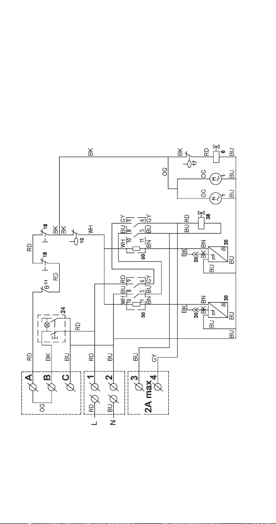
122 Part Number 000015433_03 5/20
RFF2200C QUIETQUBE HEAD SECTION
Refer to Nameplate for Voltage Rating
Connections
• A, B, & C connect to a remote panel when used -
Jumper must be removed when remote panel is used
• 1 & 2 connect to line voltage
• 3 & 4 energizes remote condensing unit (RCU)
refrigeration - 2 Amp max
241152_04
See page 140 for condensing unit wiring diagram.

Part Number 000015433_03 5/20 123
Wiring Diagram Legend RFF2200C Head Section
1 Gear motor
6 Water inlet valve
10 Low water level safety
11 Bin thermostat
17 Water level switch
18 Ice chute safety switch
24 On/Off switch
30 Rotation sensor
35 Compressor time delay by-pass
38 Solenoid valve
50 Relay
Wire Color Designation
WH White
BU Blue
GY Grey
BN Brown
BK Black
RD Red
OG Orange
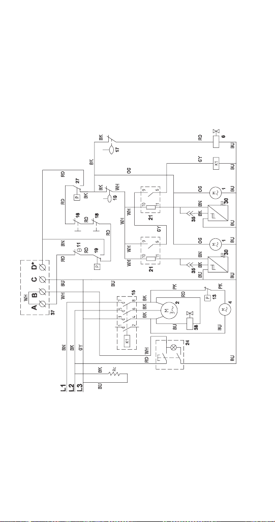
124 Part Number 000015433_03 5/20
RFF2500A AIR-COOLED
Refer to Nameplate for Voltage Rating
Connections
• A & B connect to a remote panel when used - Jumper
must be removed when remote panel is used
• C & D energize a remote alarm indication when used
241142_02
See page 145 for compressor start component wiring.
Part Number 000015433_03 5/20 125
Wiring Diagram Legend RFF2500A Air-Cooled
1 Gear motor
2 Compressor
4 Condenser fan motor
6 Water inlet valve
10 Low water level safety
11 Bin thermostat
13 Fan cycle control
15 Contactor
17 Water level switch
18 Ice chute safety switch
19 High pressure safety switch
21 Compressor relay
24 On/Off switch
25 Compressor time delay
27 Low pressure cut out
29 Compressor time delay relay
30 Rotation sensor
35 Compressor time delay by-pass
37 Remote indicator panel terminals
38 Solenoid valve
Rc Compressor crankcase heater
Wire Color Designation
WH White
BU Blue
GY Grey
BN Brown
BK Black
RD Red
PK Pink
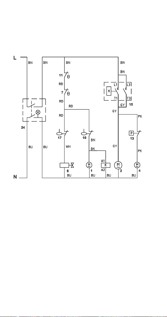
Part Number 000015433_03 5/20 127
Wiring Diagram Legend UNF0200A/UNF0300A Air-cooled
1 Gear Motor
2 Compressor
4 Condenser fan motor
6 Water Inlet valve
7 Evaporator low temperature safety thermostat
10 Low water level safety
11 Bin thermostat
12 High temperature limit (snap disc)
13 Fan cycle control
15 Contactor
17 Water level switch
21 Compressor relay
24 On/Off switch
Wire Color Designation
WH White
BU Blue
GY Grey
BN Brown
BK Black
RD Red
PK Pink
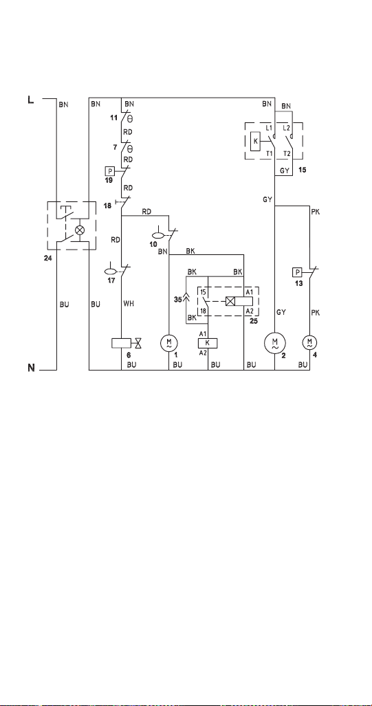

Part Number 000015433_03 5/20 129
Wiring Diagram Legend RNF0320A Air-cooled
1 Gear Motor
2 Compressor
4 Condenser fan motor
6 Water inlet valve
7 Evaporator low temperature safety thermostat
10 Low water level safety
11 Bin thermostat
13 Fan cycle control
15 Contactor
17 Water level switch
18 Ice chute safety switch
24 On/Off switch
25 Compressor time delay
35 Compressor time delay by-pass
Wire Color Designation
WH White
BU Blue
GY Grey
BN Brown
BK Black
RD Red
PK Pink
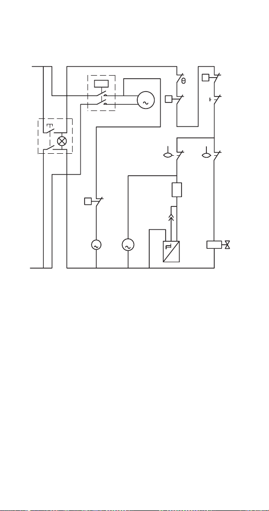
Part Number 000015433_03 5/20 131
Wiring Diagram Legend RNF0620A Air-cooled
1 Gear Motor
2 Compressor
4 Condenser fan motor
6 Water inlet valve
10 Low water level safety
11 Bin thermostat
13 Fan cycle control
15 Contactor
17 Water level switch
18 Ice chute safety switch
19 High pressure cut out
24 On/Off switch
27 Low pressure cut out
30 Rotation sensor
35 Compressor time delay by-pass
Wire Color Designation
WH White
BU Blue
GY Grey
BN Brown
BK Black
RD Red
PH Pink
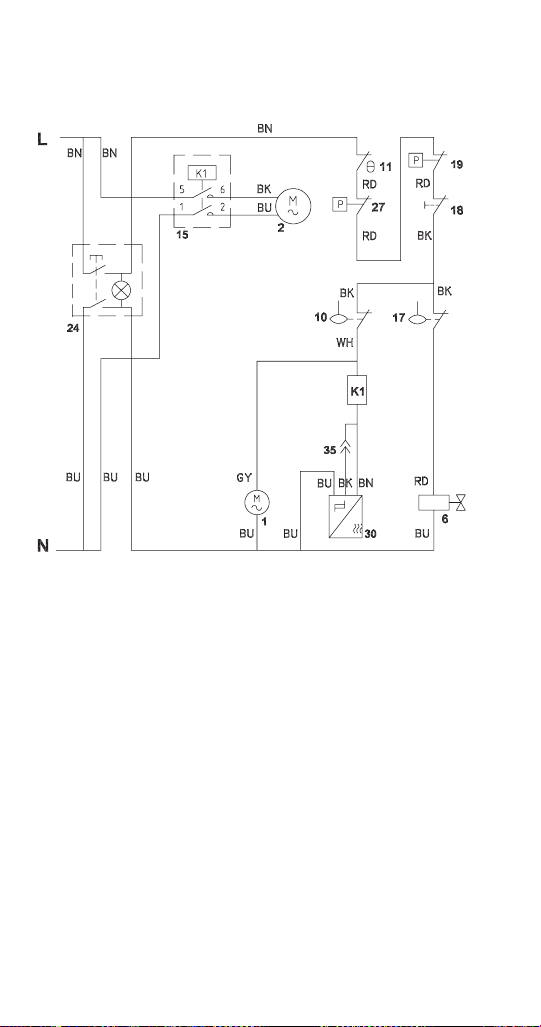

Part Number 000015433_03 5/20 133
Wiring Diagram Legend RNF0620W Water-cooled
1 Gear Motor
2 Compressor
6 Water inlet valve
10 Low water level safety
11 Bin thermostat
15 Contactor
17 Water level switch
18 Ice chute safety switch
19 High pressure cut out
24 On/Off switch
27 Low pressure cut out
30 Rotation sensor
35 Compressor time delay by-pass
Wire Color Designation
WH White
BU Blue
GY Grey
BN Brown
BK Black
RD Red
PK Pink
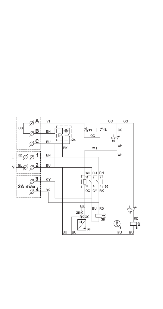
134 Part Number 000015433_03 5/20
RNF1020C QUIETQUBE HEAD SECTION
Refer to Nameplate for Voltage Rating
Connections
• A, B, & C connect to a remote panel when used -
Jumper must be removed when remote panel is used
• 1 & 2 connect to line voltage
• 3 & 4 energizes remote condensing unit (RCU)
refrigeration - 2 Amp max
• 5 terminal or junction block located on top of the
junction box.
• 6 junction box at rear of ice machine
241151_03
See page 140 for condensing unit wiring diagram.

Part Number 000015433_03 5/20 135
Wiring Diagram Legend RNF1020C Head Section
1 Gear Motor
6 Water inlet valve
10 Low water level switch
11 Bin thermostat
17 Water level switch
18 Chute safety switch
21 Relay
24 On/Off switch
30 Rotation sensor
35 Compressor time delay by-pass (Service Staff only)
38 Solenoid Valve
Wire Color Designation
A Orange
B White
BL Blue
G Grey
M Brown
N Black
R Red
V Violet
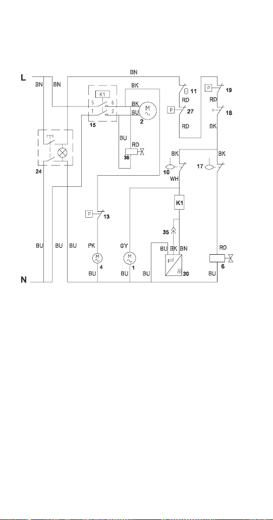
Part Number 000015433_03 5/20 137
Wiring Diagram Legend RNF1100A Air-cooled
1 Gear Motor
2 Compressor
4 Condenser fan motor
6 Water inlet valve
10 Low water level safety
11 Bin thermostat
13 Fan cycle control
15 Contactor
17 Water level switch
18 Ice chute safety switch
19 High pressure cut out
24 On/Off switch
27 Low pressure cut out
30 Rotation sensor
35 Compressor time delay by-pass
38 Solenoid
Wire Color Designation
B White
BL Blue
G Grey
M Brown
N Black
R Red
RS Pink
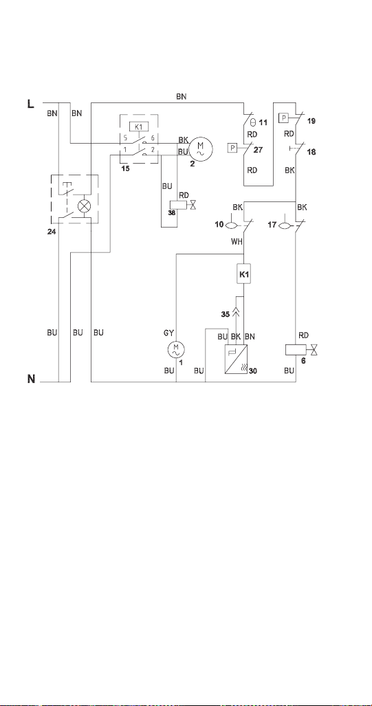
Part Number 000015433_03 5/20 139
Wiring Diagram Legend RNF1100W Water-Cooled
1 Gear Motor
2 Compressor
6 Water inlet Valve
10 Low Water Level Switch
11 Bin Thermostat
15 Contactor
17 Water level switch
18 Chute safety switch
19 High pressure safety switch
24 On/Off switch
27 Low pressure safety switch
30 Rotation sensor
35 Compressor time delay by-pass (Service staff only)
38 Solenoid Valve
Wire Color Designation
WH White
BU Blue
GY Grey
BN Brown
BK Black
RD Red
PK Pink
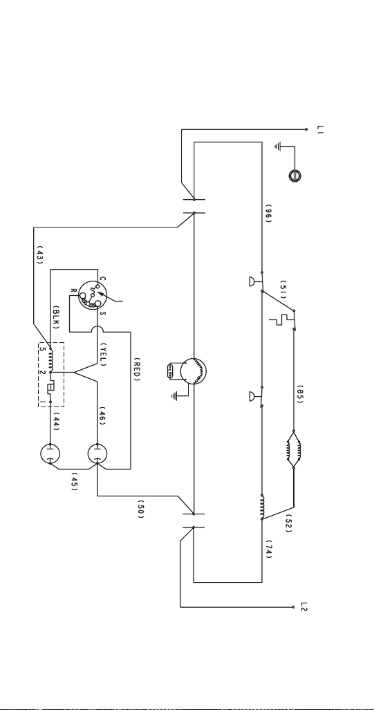
Part Number 000015433_03 5/20 141
Wiring Diagram Legend RCUF Condensing Unit
1 High pressure cutout control
2 Thermostat - Receiver heater
3 Receiver heater
RCUF1200 1 heater - RCUF1000 2 heaters
4 Low pressure cutout control
5 Contactor coil
6 Contactor contacts
7 Condenser fan motor
8 Condenser fan motor run capacitor
9 Compressor
10 Compressor overload
11 Compressor run capacitor
12 Compressor relay
13 Compressor start capacitor
Wire Color Designation
BLK Black
YEL Yellow
RED Red
Compressor Windings
C Common winding
S Start winding
R Run winding
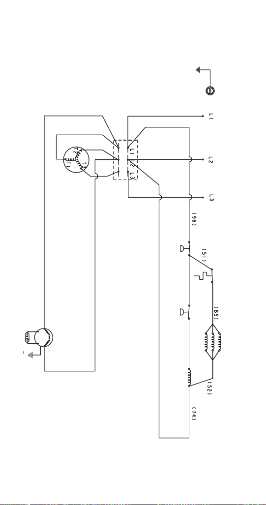

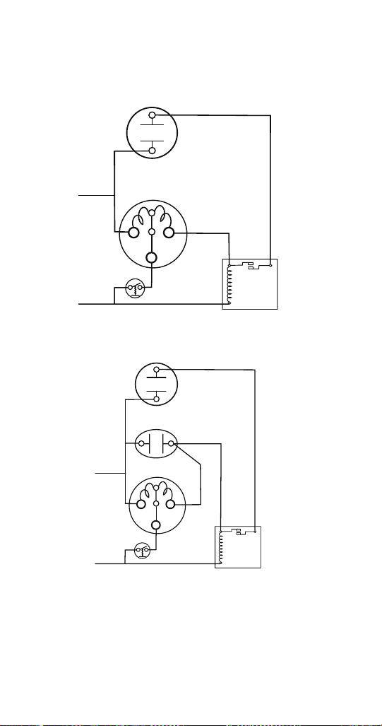
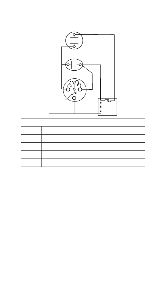

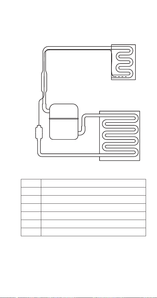
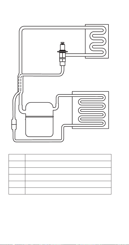
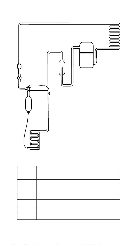
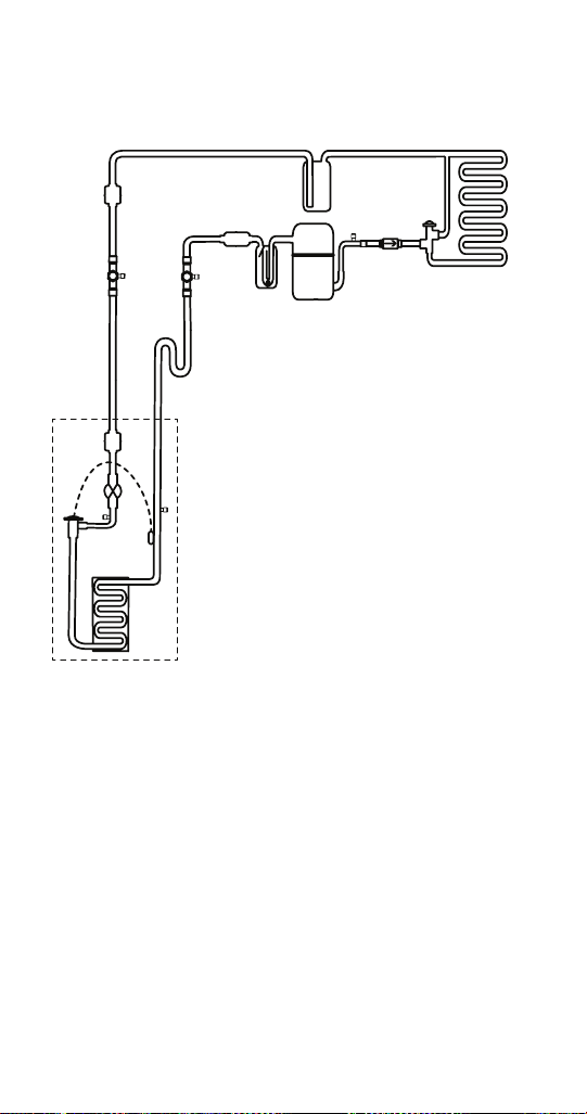
Part Number 000015433_03 5/20 151
Tubing Diagram Legend
1 Compressor
2 Check Valve
3 Head Pressure Control Valve
4 Condenser (air or water cooled)
5 Receiver
6 Condensing unit Liquid Line Drier
7 Liquid Line Shut-off Valve
8 Ice Machine Liquid Line Drier
9 Liquid Line Solenoid Valve
10 Thermostatic Expansion Valve
11 Evaporator
12 S Trap (20’ + Rise Only)
13 Suction Line Shut-off Valve
14 Suction Line Filter
15 Suction Accumulator
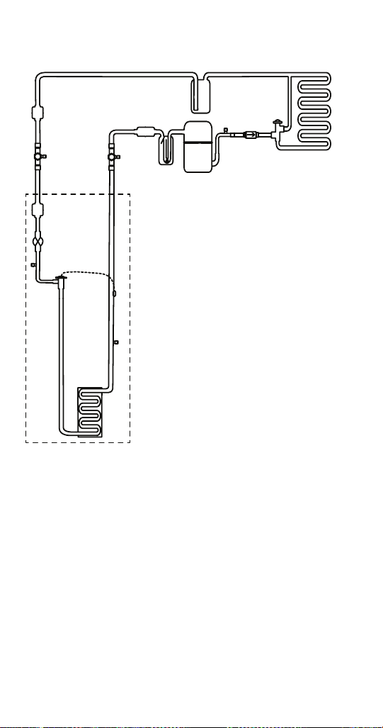

Part Number 000015433_03 5/20 153
RFF1220C & RCUF1000 Tubing Diagram Legend
1 Compressor
2 Check Valve
3 Head Pressure Control Valve
4 Condenser (air or water cooled)
5 Receiver
6 Condensing Unit Liquid Line Drier
7 Liquid Line Shut-off Valve
8 Ice Machine Liquid Line Drier
9 Liquid Line Solenoid Valve
10 Thermostatic Expansion Valve
11 Evaporator
12 Suction Line Shut-off Valve
13 Suction Line Filter
14 Suction Accumulator
NOTE: Dotted rectangle indicates ice machine head
section.
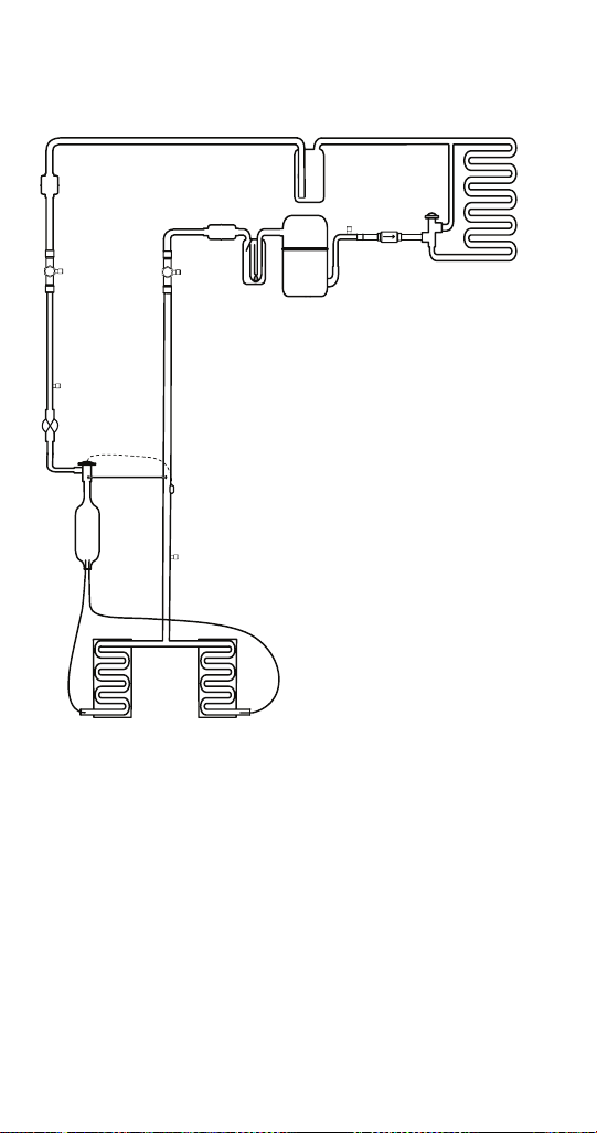

Part Number 000015433_03 5/20 155
Tubing Diagram Legend
1 Compressor
2 Check Valve
3 Head Pressure Control Valve
4 Condenser (air or water cooled)
5 Receiver
6 Condensing Unit Liquid Line Drier
7 Liquid Line Shut-off Valve
8 Ice Machine Liquid Line Drier
9 Liquid Line Solenoid Valve
10 Thermostatic Expansion Valve
11 Evaporator
12 Liquid Accumulator
13 Suction Line Shut-off Valve
14 Suction Line Filter
15 Suction Accumulator
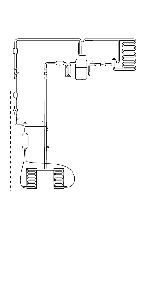

Part Number 000015433_03 5/20 157
Tubing Diagram Legend
1 Compressor
2 Check Valve
3 Head Pressure Control Valve
4 Condenser (air or water cooled)
5 Receiver
6 Condensing unit Liquid Line Drier
7 Liquid Line Shut-off Valve
8 Ice Machine Liquid Line Drier
9 Liquid Line Solenoid Valve
10 Thermostatic Expansion Valve
11 Liquid Accumulator
12 Evaporator
13 Suction Line Shut-off Valve
14 Suction Line Filter
15 Suction Accumulator