McIntosh Laboratory, Inc. 2 Chambers Street Binghamton, New York 13903-2699 Phone: 607-723-3512 www.mcintoshlabs.com
MA9000
Integrated Amplifier
Owner’s Manual

2
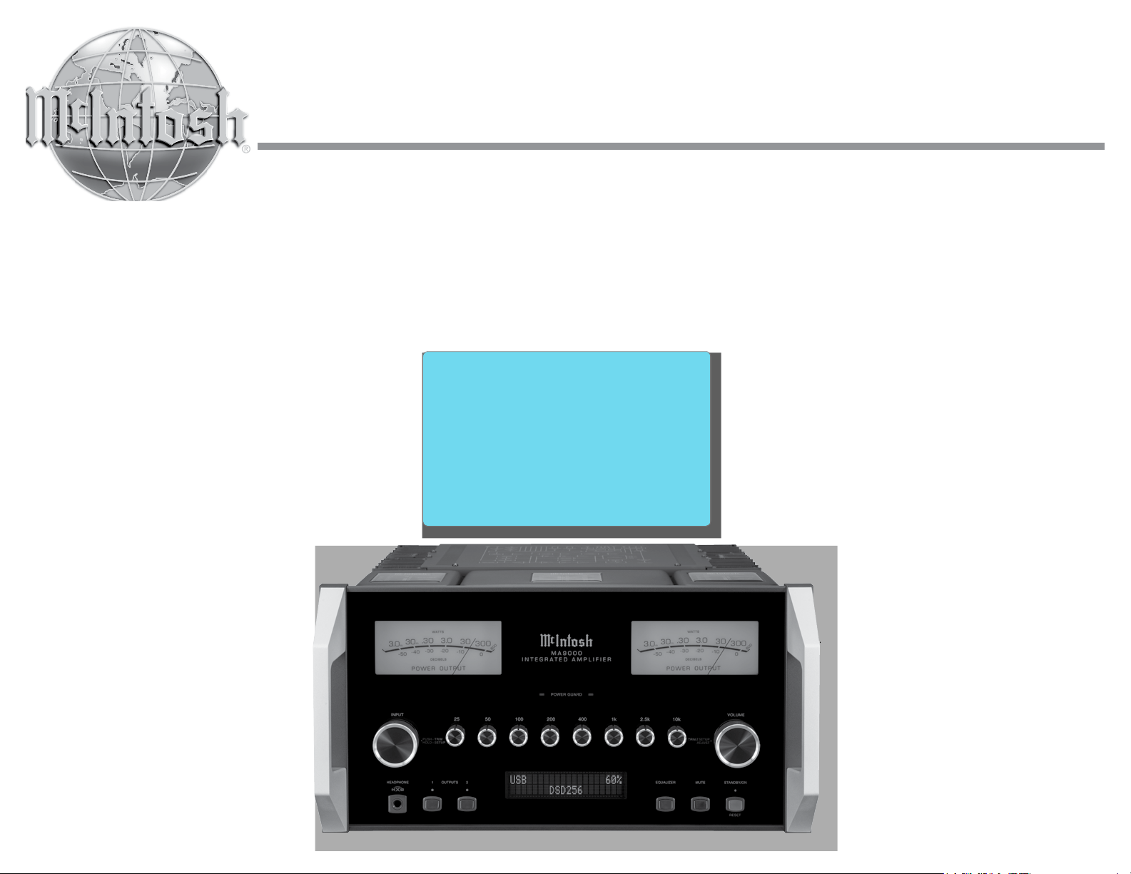
Your decision to own this McIntosh MA9000 Inte-
grated Amplifier ranks you at the very top among
discriminating music listeners. You now have “The
Best.” The McIntosh dedication to “Quality,” is as-
surance that you will receive many years of musical
enjoyment from this unit.
Please take a short time to read the information in
this manual. We want you to be as familiar as pos-
sible with all the features and functions of your new
McIntosh.
Copyright 2017 © by McIntosh Laboratory, Inc.
Table of Contents
Thank You
Please Take A Moment
Technical Assistance
If at any time you have questions about your McIntosh
product, contact your McIntosh Dealer who is familiar
with your McIntosh equipment and any other brands
that may be part of your system. If you or your Dealer
wish additional help concerning a suspected problem,
you can receive technical assistance for all McIntosh
products at:
McIntosh Laboratory, Inc.
2 Chambers Street
Binghamton, New York 13903
Phone: 607-723-3512
Fax: 607-724-0549
Customer Service
If it is determined that your McIntosh product is in
need of repair, you can return it to your Dealer. You
can also return it to the McIntosh Laboratory Service
Department. For assistance on factory repair return
procedure, contact the McIntosh Service Department
at:
McIntosh Laboratory, Inc.
2 Chambers Street
Binghamton, New York 13903
Phone: 607-723-3515
Fax: 607-723-1917
The serial number, purchase date and McIntosh Dealer
name are important to you for possible insurance
claim or future service. The spaces below have been
provided for you to record that information:
Serial Number: _______________________________
Purchase Date: _______________________________
Dealer Name: ________________________________
Important Safety Information is supplied in a separate document “Important Additional Operation Information Guide”
Safety Instructions .............................................................. 2
(Separate Sheet) ............................Important Additional
Operation Information Guide
Thank You and Please Take a Moment ...............................2
Technical Assistance and Customer Service .......................2
Table of Contents .................................................................2
General Information ............................................................3
Connector and Cable Information .......................................3
Introduction ......................................................................... 4
Performance Features ..........................................................4
Dimensions ..........................................................................5
Installation ...........................................................................6
Connections:
Rear Panel Connections .......................................................7
(Separate Sheet) ...........................................................Mc1A
Connecting Components .....................................................8
Connection Diagrams (Separate Sheet) ................. Mc2A/2B
Passthru Connections ..........................................................9
Connecting for Bi-Amplification ...................................... 10
Connecting Loudspeakers ............................................ 11-12
Remote Control and Front Panel:
Remote Control Push-buttons ........................................... 14
How to use the Remote Control ......................................... 15
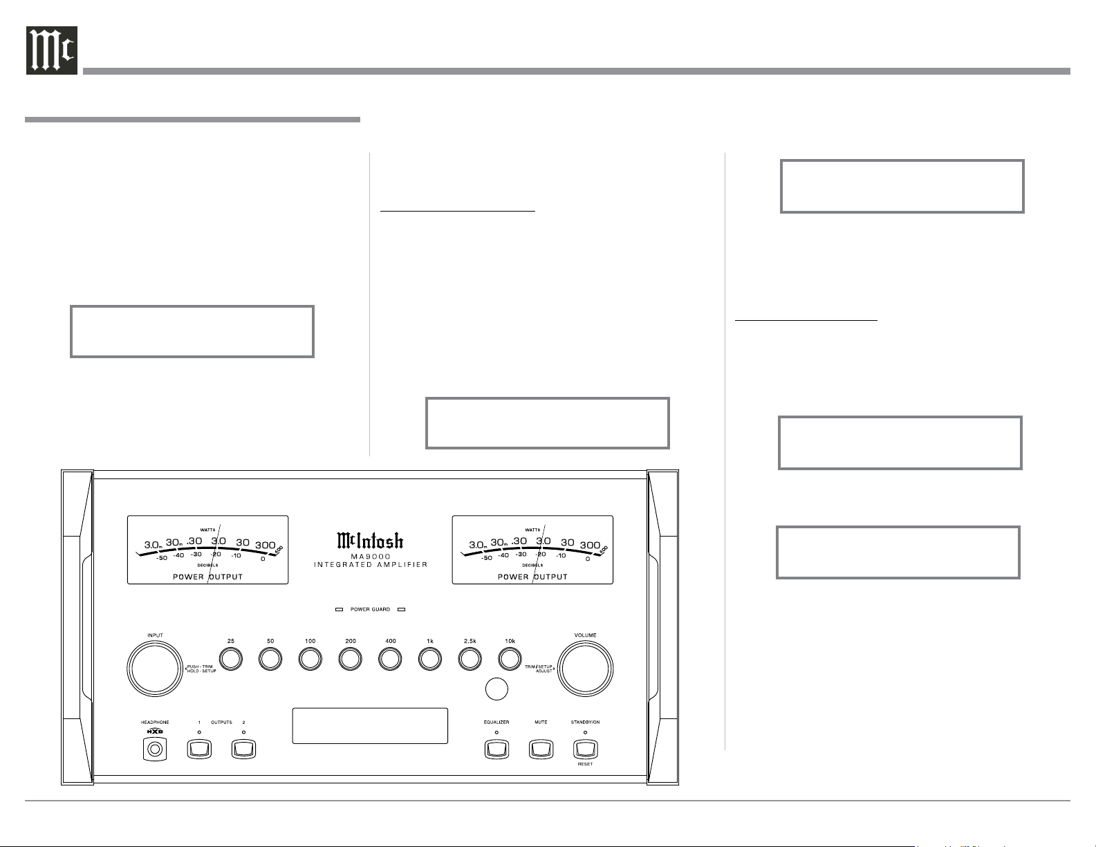
Front Panel Displays, Controls,
Push-buttons and Jack ....................................................... 16
Setup Mode:
How to Operate the Setup Mode ....................................... 17
Setup Functions:
Default Settings .........................................................17
Fir mware Version ...................................................... 17
Source Input Renaming ........................................17-19
Output Settings ..........................................................19
Power Control Triggers 1 and 2 .................................20
Data Ports ................................................................... 20
Passthru ......................................................................21
Comm Port Baud Rate ...............................................21
Remote Control Codes ............................................... 21
IR Sensor ....................................................................22
Power Mode ...............................................................22
Factory Reset .............................................................22
Microprocessor Reset ........................................................23
Operation:
How to Operate the MA9000 ....................................... 24-31
Trim Functions:
Balance .......................................................................24
Equalizer Mode ..........................................................25
Trim Level ..................................................................25
Phono Adjustments ....................................................25
Mono/Stereo Mode ....................................................26
Meter Backlight .........................................................26
Display Brightness ..................................................... 26
Headphone HXD ........................................................27
Equalizer, Trim, Mute, Headphone Jack .................... 27
Power Output Meters, Power Guard ..........................27
How to Make a Recording .......................................... 28
Using a Separate Power Amplifier .............................28
Using Output 2 and Passthru ......................................28
Equalizer Controls ...................................................... 29
Optical and Coaxial Digital Inputs ............................ 29
USB Input Operation with a Computer ...................... 30
Resetting the MA9000 to default settings .................30
Photo ......................................................................... 32
Specifications ....................................................... 33-34
Packing Instructions ................................................. 35
3
on McIntosh Power Amplifiers. A 3.5mm stereo mini
phone plug is used for connection to the Power Con-
trol, Trigger and Passthru Outputs.
Data Port Connectors
The Data Out Ports send Remote
Control Signals to Source Compo-
nents. A 3.5mm stereo mini phone
plug is used for connection.
IR IN Port Connectors
The IR IN Port also uses a 3.5mm
stereo mini phone plug and allows the
connection of other brand IR Receiv-
ers to the MA9000.
RS232-C Data Port Cable
The RS232 Data Cable is a 3.5mm stereo mini phone
plug to a sub miniature DB 9 connector:
Output Terminal Connector
When cables with spade lugs are used
for Loudspeaker Connection, the spade
lugs need an opening of at least 3/10 inch
(7.6m m)
McIntosh Plug-In Jumper Connector
The MA9000 utilizes two phono style Plug-In Jump-
ers to connect the Preamplifier Output to
the Power Amplifier Input.
Note: The Jumper Connector is available
from the McIntosh Parts Department:
McIntosh Jumper Connector Part No. 117781
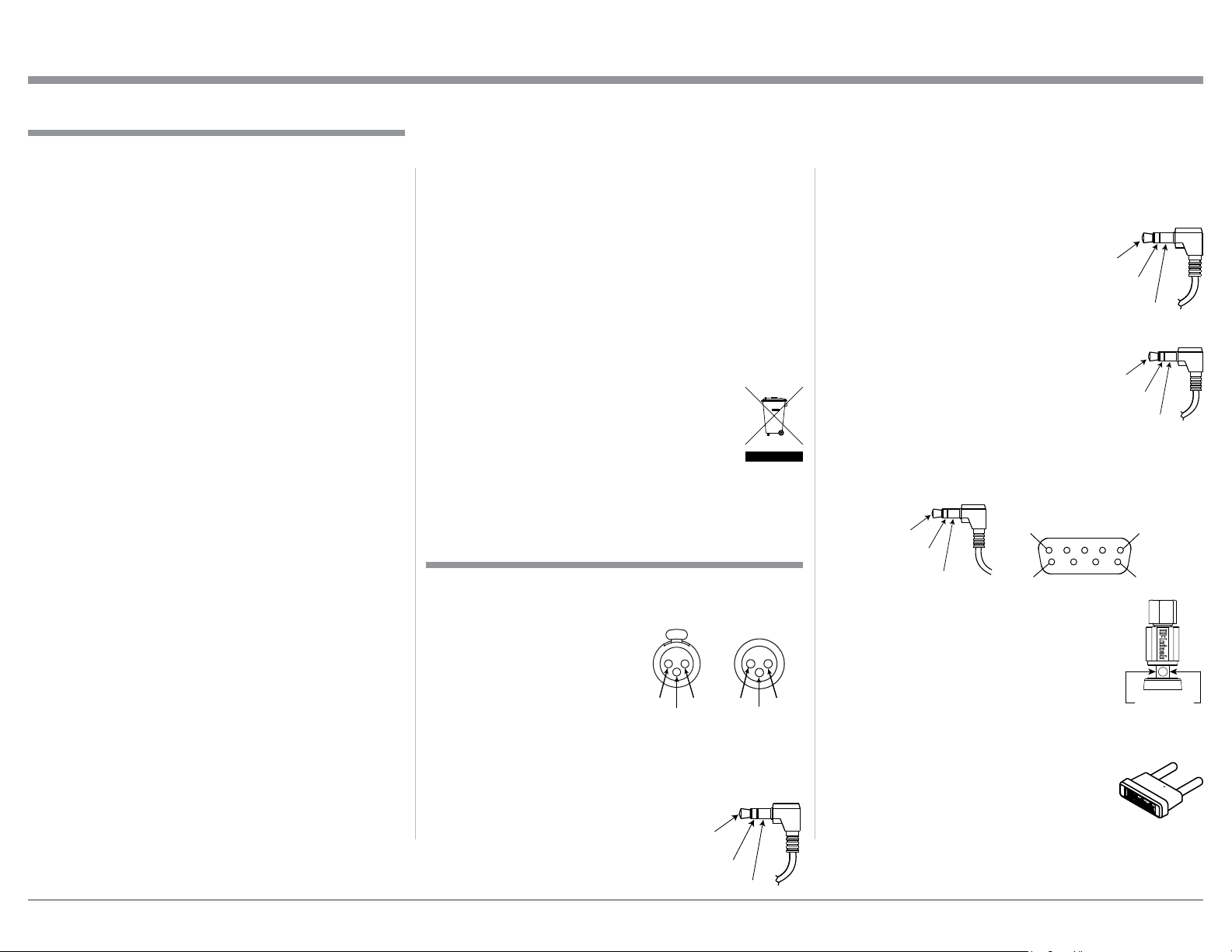
XLR Connectors
Below is the Pin configuration for the XLR Balanced
Connectors on the MA9000. Refer to the diagram for
connection:
PIN 1: Shield/Ground
PIN 2: + Output
PIN 3: - Output
Power Control and Trigger Connectors
The Power Control Trigger Output Jacks send and
Passthru Input Jack receives Power
On/Off Signals (+12 volt/0 volt)
when connected to other McIntosh
Components. An additional connec-
tion is for controlling the illumina-
tion of the Power Output Meters
1. For additional connection information, refer to the
owner’s manual(s) for any component(s) connected
to the MA9000.
2. Apply AC Power to the MA9000 and other McIn-
tosh Components only after all the system compo-
nents are connected together. Failure to do so may
cause a malfunction of system operations as the
Microprocessor’s Circuitry inside the components
is active when AC Power is applied.
3. The MA9000 includes an Power Mode Auto Off
Feature and the default setting is enabled. For
additional information including how to disable it,
refer to page 22.
4. When Power Amplifier Protection Circuitry of
the MA9000 has activated, the Front Panel Power
Guard LEDs are illuminated continuously and the
sound will be muted.
5. When the Power Transformer has overheated due
to improper ventilation and/or high ambient operat-
ing temperature, AC Power is removed from the
MA9000. Normal operation will resume when the
operating temperature is in a safe range again.
6. For the best performance and safety, it is important
to always match the impedance of the Loudspeaker
to the Power Amplifier connections. Refer to pages
11 and 12.
Note: The impedance of a Loudspeaker actually var-
ies as the Loudspeaker reproduces different
frequencies. As a result, the nominal impedance
rating of the Loudspeaker (usually measured at
a midrange frequency) might not always agree
with the impedance of the Loudspeaker at low
frequencies where the greatest amount of power
is required. Contact the Loudspeaker Manufac-
turer for additional information about the actual
impedance of the Loudspeaker before connecting
it to the McIntosh MA9000.
7. The MA9000 Remote Control is capable of operat-
ing other components. For additional information
go to www.mcintoshlabs.com.
8. The IR Input, with a 1/8 inch mini phone jack, is
configured for non-McIntosh IR sensors such as
a Xantech Model DL85K Kit. Use a Connection
Block such as a Xantech Model ZC21 when two
or more IR sensors need to be connected to the
MA9000. The signal from a connected External
IR Sensor will have priority over the signal from
the Front Panel IR Sensor.
9. When discarding the unit, comply with local rules
or regulations. Batteries should never be
thrown away or incinerated but disposed
of in accordance with the local regula-
tions concerning battery disposal.
10. For additional information on the
MA9000 and other McIntosh Products please visit
the McIntosh Web Site at www.mcintoshlabs.com.
Connector and Cable Information
Data
Signal
N/C
Data
Ground
General Information
Power
Control
Meter
Illumination
Control
Ground
Main, Trig 1&2
and Pass-Thru
IR Data
Control
Ground
N/C
General Information, Connector and Cable Information
PIN 1
PIN 6
PIN 5
PIN 9
Data In
(DB9-pin2)
Ground
(DB9-pin5)
Data Out
(DB9-pin3)
DB9
(male connector)
3/10 of an inch
(7.6millimeters)
PIN 2 PIN 1
PIN 3
PIN 1
PIN 2
PIN 3

4
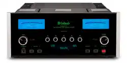
Now you can take advantage of traditional McIntosh
standards of excellence in the MA9000 Integrated
Amplifier. The Power Amplifier section of the
MA9000, with a power output of 300 watts per chan-
nel, will drive a pair of quality Loudspeakers to a high
level of performance.
The flexible Preamplifier section provides connec-
tions for various input sources and may also be used to
drive an external Power Amplifier(s).
The MA9000 reproduction is sonically transparent
and absolutely accurate. The McIntosh Sound is “The
Sound of the Music Itself.”
Introduction
Performance Features
• Power Output with Patented Autoformer
The MA9000 consists of a 300 watts per channel
Power Amplifier with less than 0.005% distortion.
The McIntosh designed and manufactured Autoformer
allows connection of 2, 4 or 8 ohm Loudspeakers. The
Power Amplifier uses ThermalTrak
1
Output Transis-
tors for lower distortion and cool operation.
• Power Guard
The patented McIntosh Power Guard circuit prevents
amplifier clipping and protects your valuable Loud-
speakers.
• Sentry Monitor and Thermal Protection
McIntosh Sentry Monitor power output stage protec-
tion circuits ensure the MA9000 will have a long and
trouble free operating life. Built-in Thermal Protection
Circuits guard against overheating.
• Electronic Switching and Balanced Connections
The Preamplifier uses Logic Circuits Controlled
1
ThermalTrak™ and ON Semiconductor are trademarks of Semi-
conductor Components Industries, LLC
Electromagnetic Switches on all inputs and operating
functions for reliable, noiseless, distortion free switch-
ing. There is a Balanced Input for connection of a
source component.
• Digital Audio Inputs
The Digital Inputs decode PCM and DSD Signals
from external sources. Coaxial and Optical Inputs
process Digital Signals up to 192kHz with 24-Bit
resolution. The Digital MCT Input Circuitry directly
decodes SACD/CD signals from an external Trans-
port component. The USB Input for streaming audio
processes Digital Signals up to 384kHz with 32-Bit
resolution, decodes up to DSD256 Digital Signals and
DXD 24-Bit with a sampling rate up to 384kHz.
• Moving Coil and Moving Magnet Phono Inputs
The MA9000 has two precision Phono Preamplifier
Circuits for Moving Coil and Moving Magnet Phono
Cartridges. Both circuits use the latest designs to
provide the lowest possible noise, distortion and flat
frequency response. The MC and MM Phono Car-
tridge Inputs have selectable loading.
• Eight Band Equalizer
The Equalizer Controls provide ±12dB at center
frequencies of 25, 50, 100, 200, 400, 1,000, 2,500 and
10,000Hz. There is also an Equalizer Bypass Mode
to remove the Equalizer from the Signal Path of any
selected input.
• Multifunction Display and Power Meters
The Front Panel Display indicates source selection,
volume levels and setup functions. The Illuminated
Power Output Meters are peak responding, and indi-
cate the power output of the amplifier.
• Power Control Output and Trigger Assignment
A Power Control connection for convenient Turn-On
of McIntosh Power Amplifiers, Source Components
and Accessories is included. The Power Control Trig-
ger Ouputs may be assigned to activate when a given
Input/Output is selected.
• PassThru Mode
The Automatic PassThru Mode allows the MA9000
to become part of a Multichannel Sound System for
DVD-Audio, SACD and Home Theater Movies.
• Remote Control
The Data Ports together with the supplied Remote
Control provide control of McIntosh Source Compo-
nents connected to the MA9000.
• Special Power Supply
The large Power Transformer, multiple filter capaci-
tors with 140 Joules of Energy Storage and regulated
Power Supply, ensures stable noise free operation even
though the power line varies.
• McIntosh Custom Binding Posts
McIntosh Patented gold plated output terminals deliver
high current output. They accept large diameter wire
and spade lugs. Banana plugs may also be used only in
the United States and Canada.
• Glass Front Panel and Super Mirror Chassis
Finish
The famous McIntosh Illuminated Glass Front Panel
uses long life Light Emitting Diodes (LEDs) and the
Stainless Steel Chassis with Super Mirror Finish
ensures the pristine beauty of the MA9000 will be
retained for many years.
Introduction and Performance Features
5
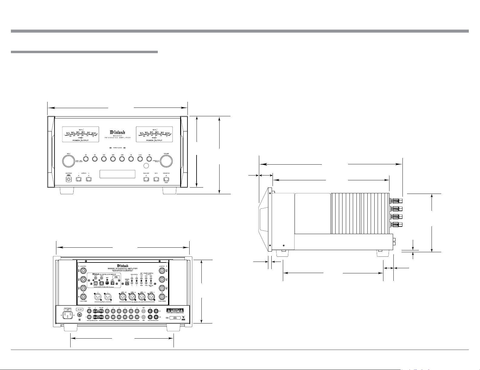
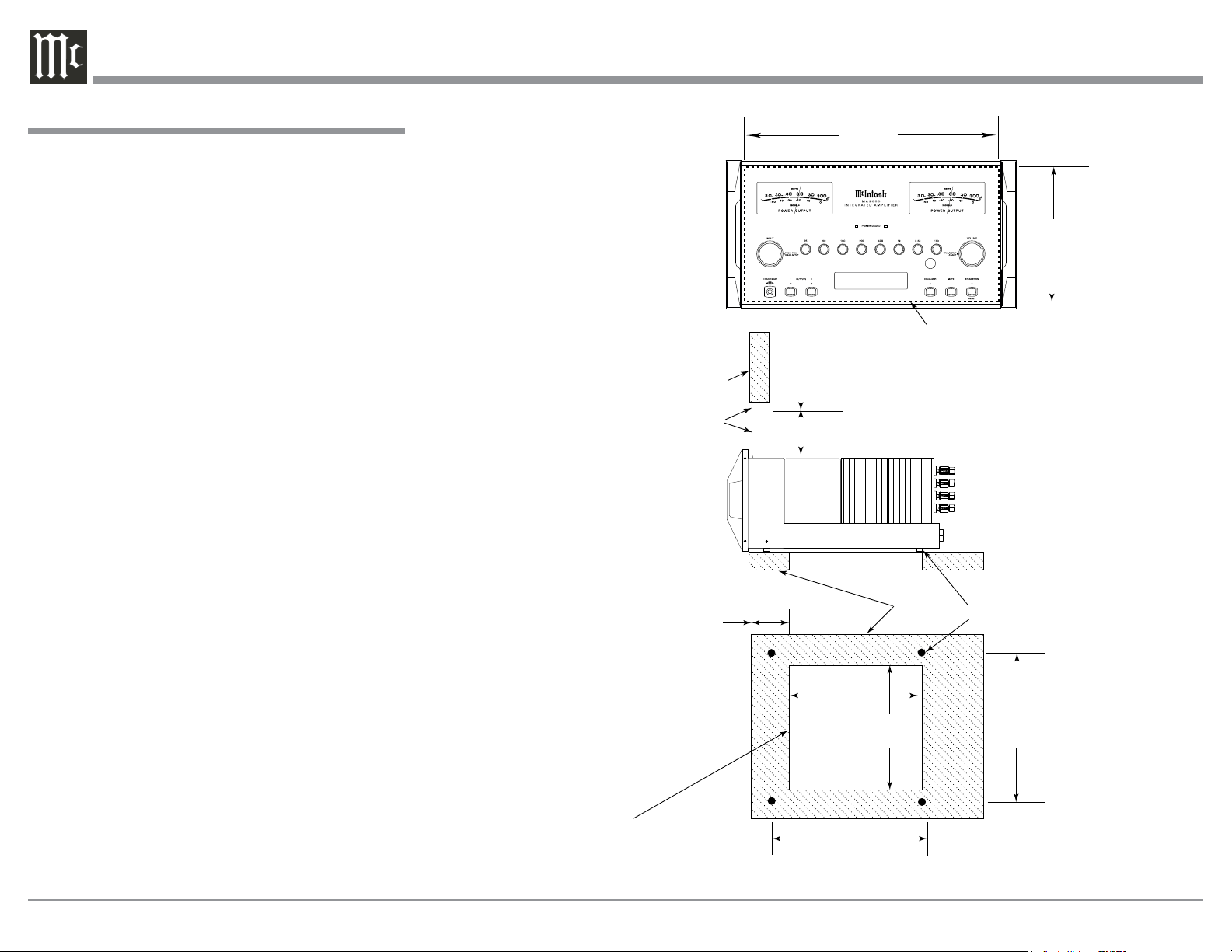
Dimensions
Dimensions
The following dimensions can assist in determining
the best location for your MA9000. There is additional
information on the next page pertaining to installing
the MA9000 into cabinets.
Front View of the MA9000
Rear View of the MA9000
Side View of the MA9000
17-1/2"
44.5cm
3/16"
0.5cm
16-13/16"
42.7cm
7/8"
2.2cm
7-15/16"
7.9cm
11-1/2"
29.2cm
19-3/4"
50.2cm
16-7/16"
41.8cm
8-1/4"
21.0cm
USB 30%
DSD256
8-13/16"
22.4cm
9-7/16"
24.0cm
2-1/4"
5.7cm
12-3/4"
32.4cm
1-1/4"
3.2cm
6
Installation
Installation
The MA9000 can be placed upright on a table or
shelf, standing on its four feet. It also can be custom
installed in a piece of furniture or cabinet of your
choice. The four feet may be removed from the bottom
of the MA9000 when it is custom installed as out-
lined below. The four feet together with the mounting
screws should be retained for possible future use if the
MA9000 is removed from the custom installation and
used free standing. The required panel cutout, ventila-
tion cutout and unit dimensions are shown.
Always provide adequate ventilation for your
MA9000. Cool operation ensures the longest possible
operating life for any electronic instrument. Do not
install the MA9000 directly above a heat generat-
ing component such as a high powered amplifier. If
all the components are installed in a single cabinet, a
quiet running ventilation fan can be a definite asset in
maintaining all the system components at the coolest
possible operating temperature.
A custom cabinet installation should provide the
following minimum spacing dimensions for cool
operation.
Allow at least 6 inches (15.24cm) above the top, 2
inches (5.08cm) below the bottom and 2 inches (5.1cm)
on each side of the Integrated Amplifier, so that air-
flow is not obstructed. Allow 20 inches (50.8cm) depth
behind the front panel. Allow 1-7/6 inch (3.66cm) in
front of the mounting panel for knob clearance. Be
sure to cut out a ventilation hole in the mounting shelf
according to the dimensions in the drawing.
USB 30%
DSD256
8-5/16"
21.1cm
17-1/16"
43.3cm
Cutout Opening for Custom Mounting
MA9000 Front Panel
Custom Cabinet Cutout
Cutout
Opening
for
Ventilation
Cutout Opening for Ventilation
Support
Shelf
Cabinet
Front
Panel
Chassis
Spacers
MA9000 Side View
in Custom Cabinet
MA9000 Bottom View
in Custom Cabinet
9-1/2"
24.1cm
6"
15.2cm
Opening
for Ventilation
16"
40.6cm
11-1/2"
29.2cm
Note: Center the cutout Horizontally
on the unit. For purposes of
clarity, the above illustration
is not drawn to scale.
10"
25.4cm
4-5/8"
11.8cm
7
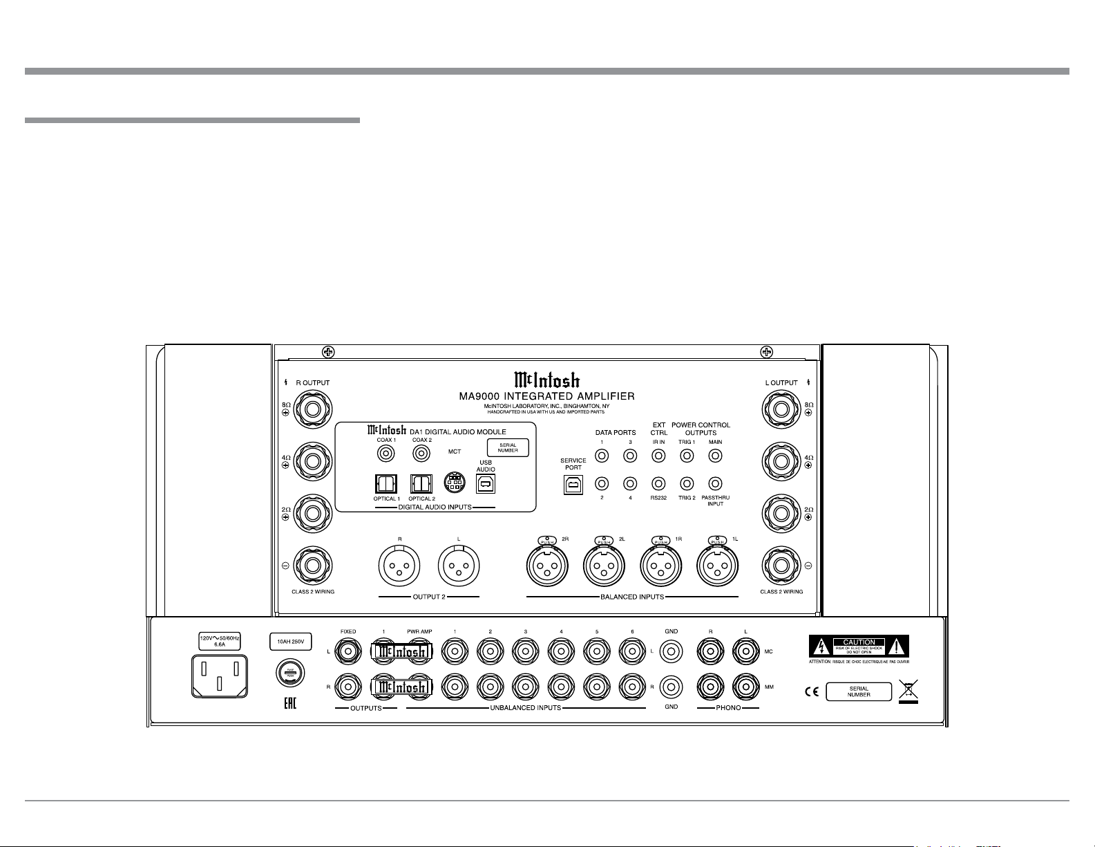
MA9000 Rear Panel Connections
The identification of Rear Panel Connections for the
MA9000 Integrated Amplifier is located on a separate
folded sheet contained in the Owner’s Manual Packet.
Refer to separate sheet “Mc1A” for the Rear Panel
Connections.
Rear Panel Connections
MA9000 Integrated Amplifer

8
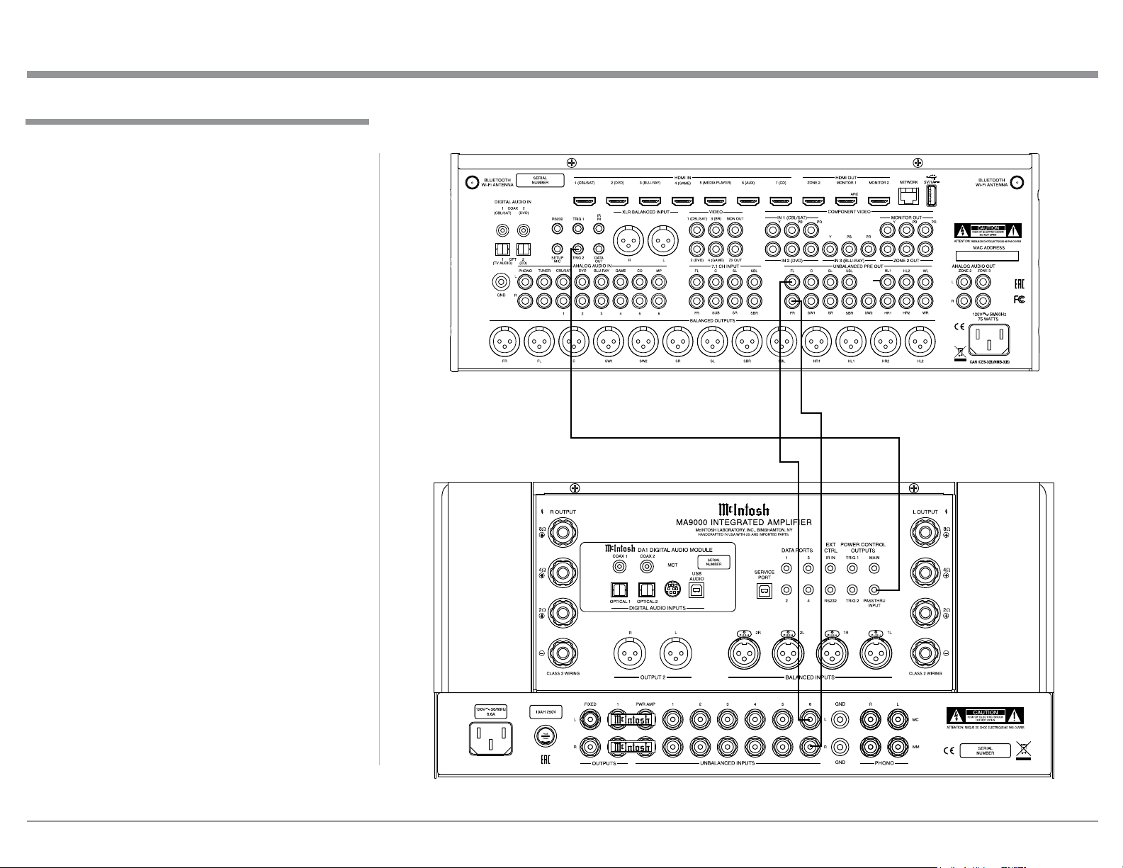
Connecting Components
The MA9000 has the ability to automatically switch
power On/Off to McIntosh Source Components via
the Power Control (Trigger) connections. The Data
Port Connections allow for the remote operation of
basic functions using the MA9000 Remote Control.
With an external sensor connected to the MA9000, re-
mote control operation of the system is possible from
another room and/or when the MA9000 is located in a
cabinet with the doors closed.
The connection instructions below, together with
the MA9000 Input and Output Connection Diagrams
located on the separate folded sheet “Mc2A/2B”, are
an example of a typical audio system. Your system
may vary from this, however the actual components
would be connected in a similar manner. For addition-
al information refer to “Connector and Cable Informa-
tion” on page 3.
Power Control Connections:
1. Connect a Control Cable from the MA9000 POW-
ER CONTROL MAIN Jack to the Power Control
In on the Turntable.
2. Connect a Control Cable from the McIntosh Turn-
table Power Control Out Jack to the Digital Audio
Player Trigger In Jack.
3. Connect a Control Cable from the Digital Audio
Player Trigger Out Jack to the SACD/CD Trans-
port Power Control In Jack.
4. Connect a Control Cable from the SACD/CD
Transport Power Control Out Jack to the AM/FM
Tuner Power Control In Jack.
5. Connect a Control Cable from the AM/FM Tuner
Power Control Out Jack to the Media Server PWR
CTRL (Power Control) In Jack.
6. Optionally connect a Control Cable from the
MA9000 POWER CONTROL TRIG (Trigger) 2
Jack to the Power Amplifier (Secondary Room)
Power Control In Jack.
7. Connect any additional McIntosh Components in a
similar manner, as outlined in steps 1 thru 4.
Data Control Connections:
8. Connect a Control Cable from the MA9000
DATA PORT Jack 3 to the SACD/CD Player Data
In Jack.
9. Connect a Control Cable from the MA9000 DATA
PORT Jack 2 to the AM/FM Tuner Data In Jack.
10. Connect a Control Cable from the MA9000 Jack 1
to the Media Server Data In Jack.
11. Connect any additional McIntosh Components in a
similar manner, as outlined in steps 8 thru 10.
Sensor Connection:
12. Optionally, connect the cable with stereo mini
plug coming from the compatible External Sensor
to the EXT CTRL (External Control) IR IN Jack
on the MA9000. Refer to page 3 “General Infor-
mation, note 8” for additional information.
Audio Connections:
13. Connect Balanced Cables from the MA9000
BALANCED INPUT 1L & 1R Connectors to the
Media Server Audio Output Balanced Connectors.
14. Connect Audio Cables from the MA9000 Number
1 UNBALANCED Jacks to the AM/FM Tuner
UNBALanced Output Jacks.
15. Connect the Audio Cables coming from the Turn-
table to the MA9000 MC (for a Moving Coil Car-
tridge) or MM (for a Moving Magnet Cartridge)
INPUT Jacks.
16. Optionally, connect Audio Cables from the
MA9000 OUTPUT 2 Jacks to the Power Amplifier
(Secondary) Input Jacks.
17. Connect any additional Components in a similar
manner, as outlined in steps 13 thru 16.
Optional Digital Audio Connections:
18. Connect an Optical Cable from the MA9000
OPTICAL 1 Digital Audio Input Connector to the
Digital Audio Out Optical Connector on the Digi-
tal Audio Player.
19. Using the “DIN Cable-Twisted Pair” cable (sup-
plied with a MCT Transport), connect the cable
from the MA9000 MCT DIGITAL AUDIO IN-
PUT Connector to the SACD/CD Transport DIN
Output Connector.
Optional USB Connection:
20. Connect a USB cable with (Type A to Type B)
connectors from the MA9000 USB D/A Digital
Audio Input to an available USB connector.
Ground Connections:
21. Connect the Ground Cable coming from the Turn-
table to the MA9000 GND Binding Post.
Notes: 1. If the MA9000 is part of a Home Theater
System, proceed to “PassThru” connection on
page 9.
2. When the MA9000 will used together with a
separate Power Amplifier for Bi-Amplification
of a Loudspeaker System, proceed page 10.
Connecting Components
9
The MA9000 can be part of a Multichannel Sound
System for BLU-RAY Audio, DVD Audio and Home
Theater Movies. The Right and Left Front Channels
from an Audio/Video Control Center can “Passthru”
the MA9000. In the following example the UNBAL-
ANCED 6 Input will become the “Passthru” input:
1. Connect Audio Cables from the A/V Processor
FL (Front Left) and FR (Front Right) Channel
Outputs to the MA9000 UNBALANCED Num-
ber 6 INPUTS Left and Right Jacks.
2. Connect a Control Cable from the A/V Proces-
sor TRIGger 2 Output to the MA9000 POWER
CONTROL PASSTHRU INPUT Jack.
Note: Refer to Setup “Passthru” on page 21 to assign
the Number 6 INPUT as the “Passthru” Input.
3. Proceed to “Connecting Loudspeaker” on
Page 11.
Passthru Connections
Passthru Connections
A/V Processor
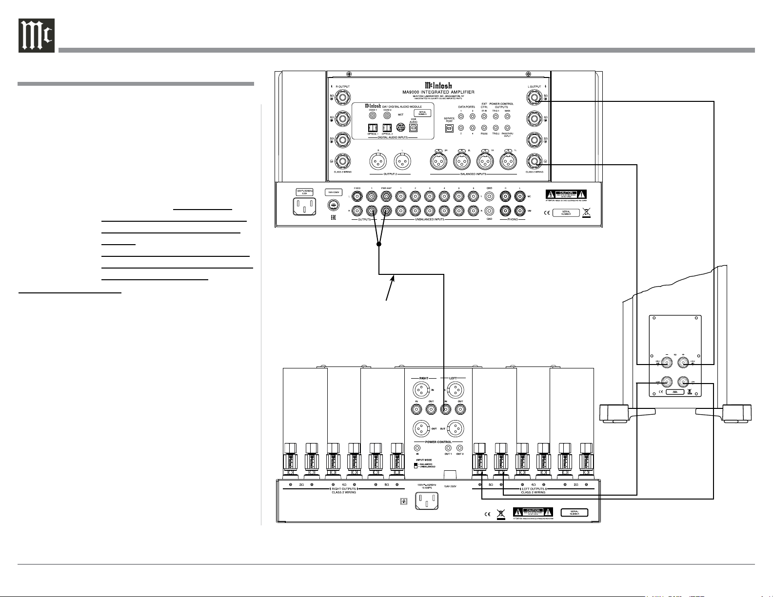
10
The MA9000 Power Amplifier Circuitry, together
with an additional separate Power Amplifier, may
be used to Bi-Amplify a Loudspeaker System. In the
illustration on this page, the Power Amplifier of the
MA9000 is connected to the Midrange/High Fre-
quency Section of the Loudspeaker. The additional
separate Power Amplifier is connected to the Low
Frequency Section of the Loudspeaker System.
Warning: The Loudspeaker System used for
Bi-Amplification must have the
jumpers removed from between the
MID/HIGH and LOW Frequency
Sections of the Loudspeaker System.
Failure to remove them could result
in damage to the MA9000 and/or the
separate Power Amplifier.
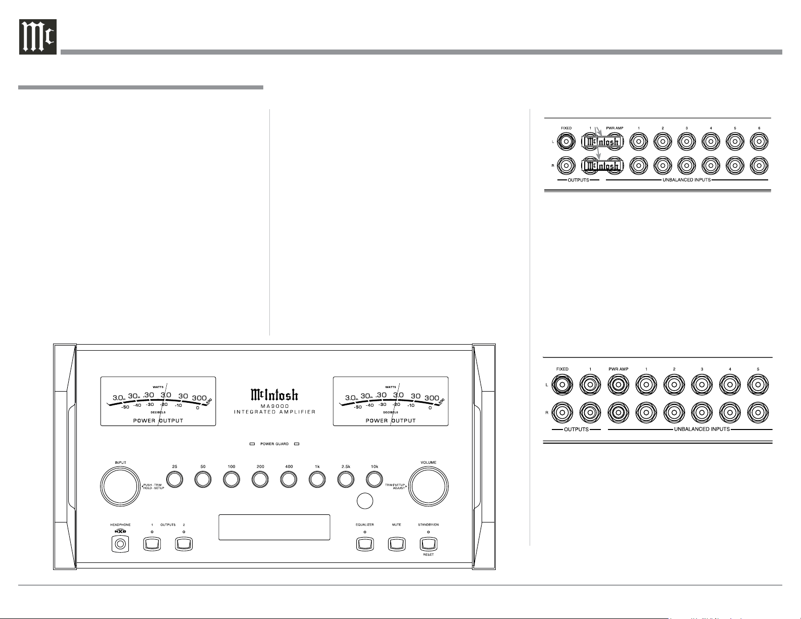
MA9000 Connections:
1. Remove the “McIntosh Jumpers” from between
the OUTPUT 1 Jacks and the PWR AMP In Jacks
located on the Rear Panel of the MA9000.
Note: Place the “McIntosh Jumper” in a safe place
for possible future use.
2. Using a pair of shielded RCA Type Audio “Y”
Adapters connect the OUTPUT 1 Jacks to the
PWR AMP In Jacks, for both Left and Right
Channels.
3. Connect the remaining unconnected part of the
“Y” Adapters to the separate Power Amplifier.
4. Referring to the Loudspeaker Connection Instruc-
tions on page 11, and in the Owner’s Manual sup-
plied with the Power Amplifier and Loudspeaker,
connect the MA9000 Output Terminals to the
Loudspeaker MID/HIGH Input Terminals.
Note: The Loudspeaker Connection illustrations
on this page are for the Left Channel. Con-
nect the Right Channel Loudspeaker in the
same manner.
Connecting for Bi-Amplification
Connecting for Bi-Amplification
+
-
Left Channel
Loudspeaker
“Y” adapter Cable
Power Amplier
11
Caution: Do not connect the AC Power Cord to the
MA9000 Rear Panel until after the Loudspeaker
Connections are made. Failure to observe this
could result in Electric Shock.
The connection instructions below, together with the
MA9000 Connection Diagram located on the separate
folded sheet “Mc2B”, is an example of a typical audio
system. Your system may vary from this, however the
actual components would be connected in a similar
manner. For additional information refer to “Connec-
tor and Cable Information” on page 3.
The McIntosh MA9000 Power Amplifier Circuitry
is designed for Loudspeakers with an impedance of
2 ohms, 4 ohms or 8 ohms. Connect a single Loud-
speaker only to the Right and Left Output Terminals.
When connecting Loudspeakers to the MA9000
it is very important to use cables of adequate size, so
there is little to no power loss in the cables. The size is
specified in Gauge Numbers or AWG (American Wire
Gauge). The smaller the Gauge number, the larger the
wire size:
Loudspeaker Cable Distance vs Wire Gauge Guide
Loudspeaker
Impedance
25 feet
(7.62 meters)
or less
50 feet
(15.24 meters)
or less
100 feet
(30.48 meters)
or less
2 Ohms
12AWG 10AWG 8AWG
4 Ohms
14AWG 12AWG 10AWG
8 Ohms
16AWG 14AWG 12AWG
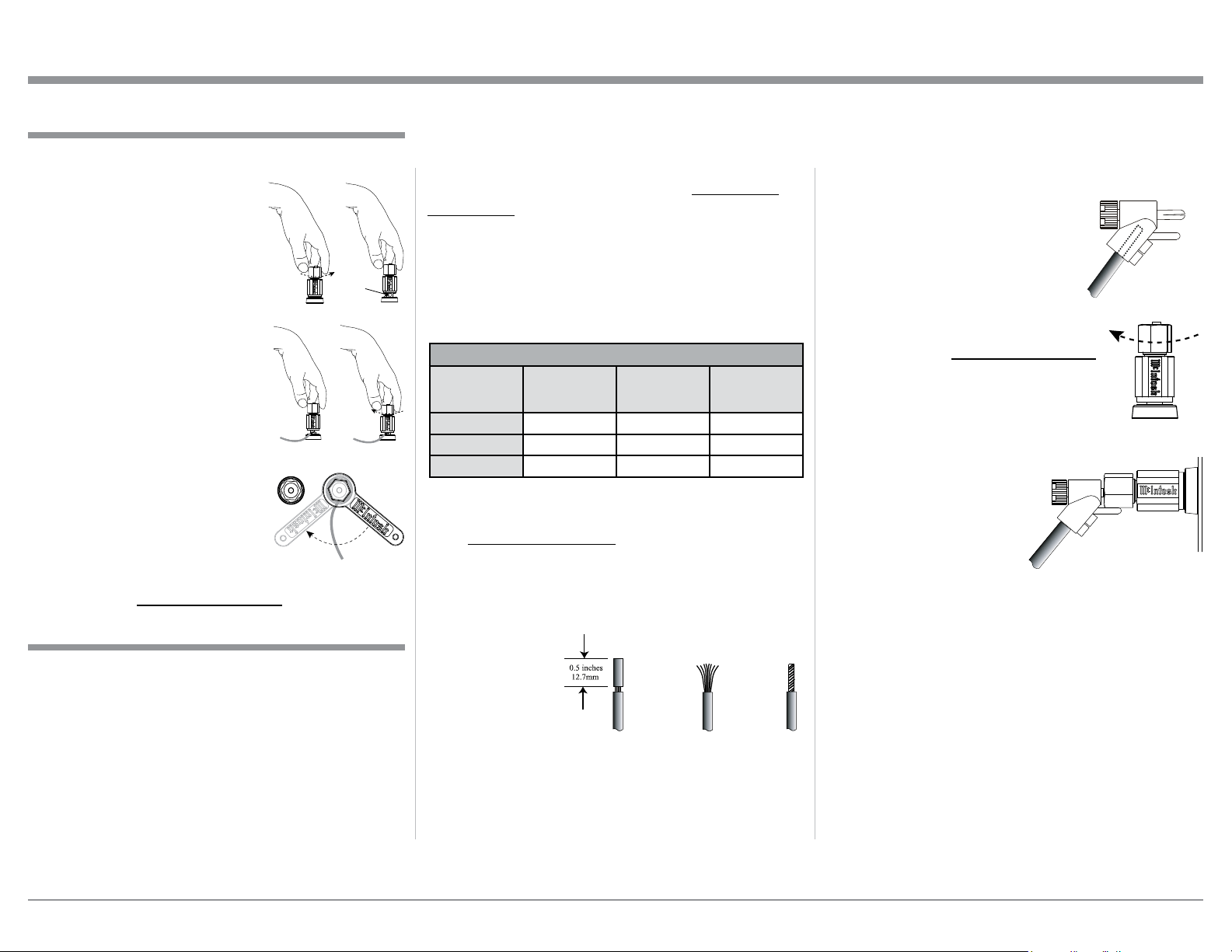
1. Prepare the Loudspeaker Hookup Cable for attach-
ment to the MA9000 Power Amplifier Circuitry:
Bare wire cable ends:
Carefully remove sufficient insulation from the
cable ends, refer to figures F, G & H. If the cable
is stranded, carefully twist the strands together
as tightly as possible.
Notes: 1. If desired, the twisted ends can be tinned
with solder to keep the strands together.
2. The prepared bare wire cable ends may be
inserted into spade lug connectors.
3. Banana plugs are for use in the United
States and Canada only.
Banana Plugs are for use in the United States and
Canada only:
2. Attach the previously prepared bare wire cable ends
into the banana plugs and secure
the connections. Refer to figure I.
3. Rotate the Output Terminal Post
clockwise until it is nger tight.
Refer to gure J. Then using the
McIntosh Wrench, rotate the top
of the Output Terminal one quarter
of a turn (90°). Do not over tighten.
Refer to gure E.
4. Referring to figure K, connect the
Loudspeaker hookup cables with
banana plugs into the hole at the
top of the terminal to
the MA9000 Negative
Output Terminal and
Positive Output Terminal
indentified as 2Ω (ohms),
4Ω (ohms) or 8Ω (ohms)
connection to match the
impedance of the Loudspeaker, being careful to
observe the correct polarities.
Note: The illustration located on the separate
folded sheet “Mc2B” is for connection to an
8Ω (ohms) Loudspeaker.
If the Loudspeaker’s impedance is in-between
the available connections, use the nearest lower
impedance connection. Refer to “General Informa-
tion” Note 6 on page 3 for additional information.
WARNING: Loudspeaker terminals are hazard-
ous live and present a risk of electric
shock. For additional instruction on
making Loudspeaker Connections con-
tact your McIntosh Dealer or McIn-
tosh Technical Support.
Output Terminals
When connecting the Loudspeaker Hookup Cables to
the MA9000 Amplifier Output Terminals please fol-
low the steps below:
1. Rotate the top of the Output
Terminal Post counterclock-
wise until an opening appears.
Refer to gures A and B.
2. Insert the Loudspeaker
hookup cable into the Output
Terminal Post opening or the
cable spade lug around the
center post of the Output Ter-
minal. Refer to gure C.
3. Rotate the top of the Output
Terminal Post clockwise
until it is nger tight. Refer to
gure D.
4. Place the supplied McIntosh
Wrench over the top of the
Output Terminal and rotate it
one quarter of a turn (90°) to
secure the Loudspeaker Cable
Connection. Do not over tighten. Refer to gure E.
How to Connect Loudspeakers
Figure F
Figure G
Figure H
Figure I
Figure A
Opening
Figure B
Figure C Figure D
Figure E
Figure J
Figure I
Figure K
12
5. Connect the MA9000 power cord to an active AC
outlet.
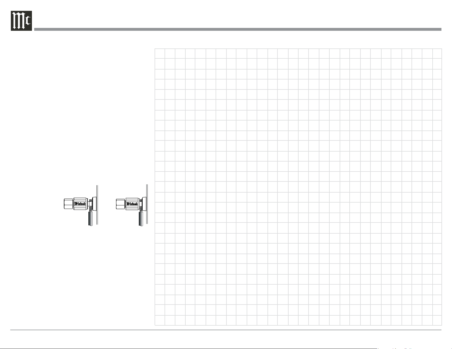
Spade Lug or Wire Connections:
6. Connect the Loudspeaker hookup cables to the
MA9000 Negative Output Terminal and Posi-
tive Output Terminal indentified as 2Ω (ohms),
4Ω (ohms) or 8Ω (ohms) connection to match the
impedance of the Loudspeaker, being careful to
observe the correct polarities. Insert the spade
lug connector or prepared section of the cable end
into the terminal side access hole, and tighten the
terminal cap until the cable is firmly clamped into
the terminals so the lugs or wire cannot slip out.
Refer to figures L and M.
Note: The illustration located on the separate folded
sheet “Mc2B” is for connection to an 8Ω
(ohms) Loudspeaker.
If the Loudspeaker’s impedance is in-between the
available connections, use the nearest lower im-
pedance connection. Refer to “General Informa-
tion” Note 6 on page 3 for additional information.
WARNING: Loudspeaker terminals are hazard-
ous live and present a risk of electric
shock. For additional instruction on
making Loudspeaker Connections con-
tact your McIntosh Dealer or McIn-
tosh Technical Support.
7. Connect the MA9000 power cord to an active AC
outlet.
Connecting Loudspeakers
Figure L
Figure M

13
14
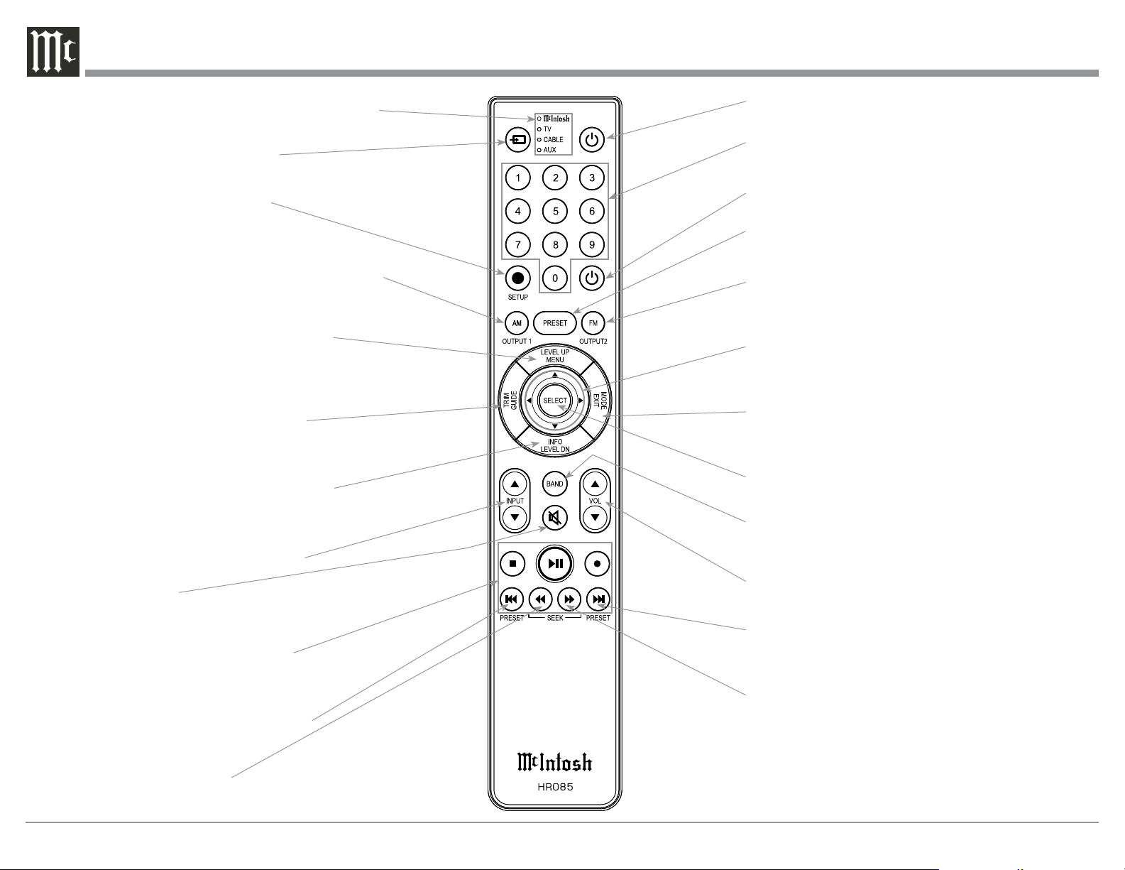
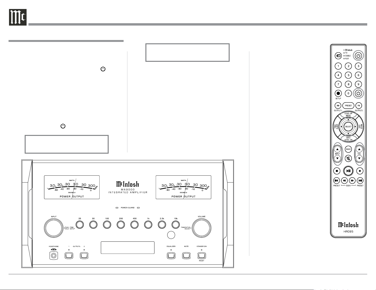
Note: Push-buttons whose function is not identified
above are for use with other McIntosh Products.
Press to Power the Integrated Amplifier ON
Use to select tuner presets, direct ac-
cess an AM/FM Station Frequency,
disc tracks or any numbered operation
Mutes the audio
Adjusts the VOLume level up or down
Selects FM Tuner Operating Functions, select Output
2 when used with the SETUP/shift Push-button and
Track Selection on certain McIntosh CD Players
LEDs illuminate during the time a remote command
is sent and when programming the remote control
Press the Trim Push-button and then the
LEVEL UP Push-button to select and adjust
various functions. MENU is used with Mc-
Intosh Models displaying choices on a video
screen
Press to Power the Integrated Amplifier OFF
Scrolls through the available INPUTs
Used to SELECT/Enter the indicated choice
Use p and q to tune Up or Down the AM/FM
Dial, use u and t for the next or previous HD
Radio Program (were applicable)
Activates the TRIM Mode. GUIDE is
used with McIntosh Models displaying
instructions on a video screen
Press to change Broadcast BANDs on a
connected Tuner. Select certain functions
on a variety of McIntosh Models
Select the DEVICE to issue a remote
control command to
Direct access to stored Tuner PRESETS when
used with the numeric Push-buttons (0 thru 9)
Press the Trim Push-button and then the
LEVEL DOWN Push-button to select and
adjust various functions. INFO is used with
McIntosh Models displaying information on
a video screen
Selects transport functions of STOP,
PLAY/PAUSE, RECORD, BACK for
the previous-selection, FAST-RE-
VERSE, FAST-FORWARD and NEXT
for the next selection
Selects Previous Tuner Station PRESET
Tuner scans Down the dial
to SEEK the next Station
Selects Next Tuner Station PRESET
Tuner scans Up the dial to
SEEK the next Station
SETUP Push-button is used as a
“Shift Key” to select a function
with blue color nomenclature
HR085 Remote Control Push-Buttons
Selects AM Tuner Operating Functions, select Output
1 when used with the SETUP/shift Push-button and
Track Selection on certain McIntosh CD Players
EXIT the TRIM Menu and is used with McIntosh
Models displaying information or choices on a video
screen
15
How to use the HR085 Remote Control
How to use the Remote Control
The supplied MA9000 Remote Control (HR085) is
capable of directly controlling the functions of con-
temporary McIntosh Source Components connected to
the MA9000 via the Data Ports.
Notes: 1. If at any time the MA9000 seems unrespon-
sive to the HR085 Remote Control Commands,
press the DEVICE Push-button to select
first.
2. For additional information on using the
HR085 Remote Control with the McIntosh
Model, please refer to the “How to Operate”
starting on page 24.
3. For additional information on assigning the
Data Ports, refer to “Data Ports” on page 20.
Trim
Press the TRIM Push-button until the desired Trim
function (Balance, Trim Level, etc.) appears on the
MA9000 Front Panel Display, then press the LEVEL
Up or Down Push-button to adjust the Trim setting.
Note: Press the TRIM Push-button to recall the last Trim
function selected. For additional information on
using the Trim Functions refer to “How to Oper-
ate” page on 24.
Output Selection
Press the BLUE (Setup) Push-button followed by
the AM (Output 1) or FM (Output 2) Push-button, to
control the Rear Panel Audio OUTPUTS 1, 2 (ON or
OFF) and Power Control TRIG 1 / TRIG 2.
Note: For additional information on assigning the Out-
puts (1 and 2) and Power Control Triggers (1 and
2) refer to pages 19 and 20.

16
USB 30%
DSD256
IR Sensor receives
commands from a
Remote Control
STANDBY/ON Push-button with indica-
tor switches the MA9000 ON or OFF
(Standby) and resets the microprocessors
MUTE Push-button mutes the
audio from the Loudspeakers
and Headphones
Meter indicates the
Right Channel Output
of the amplifier
LED indicates when the Left
Channel Amplifier POWER
GUARD circuit activates
Meter indicates the
Left Channel Output
of the amplifier
LED indicates when the Right
Channel Amplifier POWER
GUARD circuit activates
OUTPUT 1 and 2 Push-buttons
with indicators, switch Preamplifier
Output (Loudspeakers) 1 and 2 On
or Off
INFORMATION DISPLAY indicates the
Sources, Volume, other Audio Settings,
Operational Functions and Setup Mode
Settings
EQUALIZER Push-button with
indicator, when deactivated the
audio signal bypasses the Equal-
izer Controls
EQUALIZER Controls increase or de-
crease the volume levels at the Center Fre-
quencies of 25Hz, 50Hz, 100Hz, 200Hz
400Hz, 1,000Hz, 2,500Hz and 10,000Hz
VOLUME Control allows ad-
justment of the listening level
for both channels. Also used
to change the various TRIM
and SETUP Functions
Connection for low impedance
dynamic headphones, for private
listening
INPUT Control used to
select a source for listening
and recording. The control is
also used to enter the TRIM
or SETUP Modes and select
the various functions
Front Panel Displays, Controls, Push-buttons and Jack
17
Your McIntosh MA9000 has been factory configured
to allow immediate enjoyment of superb audio with-
out the need for further adjustments. If you wish to
make changes to the factory default settings, a Setup
Feature is provided to customize the operating settings
using the Front Panel Information Display. Refer to the
MA9000 Front Panel Illustration on the previous page
while performing the following steps.
Note: If the MA9000 is currently On, proceed to
step 2.
1. Press the STANDBY/ON Push-button on the Front
Panel or press the (Power ON) Push-button on
the Remote Control to switch On the MA9000.
The MA9000 will go through a brief startup
initialization with the Front Panel Information
Display first indicating “MA9000”, followed by
the last used source and volume setting. This is
followed by the volume setting indication starting
at zero and then increasing to the last used volume
setting. Refer to figure 1.
2. Press and hold in the INPUT Control until
the Front Panel Information Display indicates
“MA9000 V1.00, (or higher Main Firmware ver-
sion) - S/N: AFK____” (Serial Number). Refer
to figure 2.
3. Rotate the INPUT Control to select the Setup
Mode Menu item, “SETUP: Inputs, (Hold IN-
PUT)”. Continue to rotate the INPUT CON-
TROL to view the other SETUP Mode Options.
Refer to figure 3.
4. To exit from the SETUP Mode, press and hold in
the INPUT Control and the Front Panel Display
will indicate its normal display. Refer to figure 1.
The MA9000 functionality is controlled by internal
software that is know as Firmware. There are two
Firmware Identification Numbers for the MA9000.
The first Firmware Number is for the Main Circuitry
of the MA9000 and can be identified at any time by
How to Operate the Setup Mode
The Default Settings Chart below indicates the Func-
tion Name, Default Setting and the Page Number for
additional information.
Default Settings
Firmware Version
Default Settings
Function Name Setting Page No.
MA9000 V_._ _ 17
DA1 V_._ _ 17
INPUTS On / Rename 17-18
OUTPUTS (1 & 2) Switched 19
TRIGGER 1 Output 1 20
TRIGGER 2 Output 2 20
DATA PORTS
(1 thru 4)
All Data 20
PASSTH RU OFF 21
USB Automute ON 21
RS232 (Rate) 115200 Baud 21
Remote Control Codes Normal 22
IR Sensor Enabled 22
Power Mode Enabled 22
Setup
Figure 2
MA9000 V1.00
S/N: AFK____
Figure 1
BAL 1
15%
The MA9000 provides the ability to switch unused
INPUTS Off (or back On if they have been previously
switched Off). The default INPUT Names can be
changed to match the name of the component con-
nected to it or any other custom name desired (within
10 Characters).
INPUT SWITCHED ON/OFF:
In the following example, the UNBAL 4 Input will be
switched Off.
Note: When an INPUT is swiched Off, its name will
no longer appear on the Front Panel Informa-
tion Display when using the INPUT Control
(Front Panel or Remote Control).
1. Press and hold in the INPUT Control to enter the
SETUP MODE. Refer to figure 2.
Input Settings
utilizing the Setup Mode.
1. Press and hold in the INPUT Control to enter
Setup Mode.
2. Referring to the Front Panel Information Display-
the number after the character “V” is the Firm-
ware number. Refer to figure 2.
To view the second Firmware Number, which is for
the Digital Audio Circuitry of the MA9000, perform
the following steps:
3. Press and hold in the INPUT Control to enter
Setup Mode.
4. Rotate the INPUT Control until the Front Panel
Information Display indicates “DA1 Firmware,
V1.00” (or higher Digital Audio Firmware ver-
sion). Refer to figure 4.
5. To exit the Setup Mode, press the INPUT Control.
Figure 3
SETUP: Inputs
(Hold INPUT)
Figure 4
DA1 FIRMWARE
V1.00
18
ready to be changed. Refer to figure 9.
15. Rotate the VOLUME (ADJUST) Control to change
the character “B” to “M”. Refer to figure 10.
16. Rotate the INPUT Control until the character “A”
is flashing, then rotate the VOLUME (ADJUST)
Control to change the character “A” to “E”. Refer
to figure 11.
17. Rotate the INPUT Control until the character “L”
is flashing, then rotate the VOLUME (ADJUST)
Control to change the character “L” to “D”. Refer
to figure 12.
18. Rotate the INPUT Control until the “_” empty
space to the right of character D is flashing, then
rotate the VOLUME (ADJUST) Control to change
the “_” empty space to character to “I”. Refer to
figure 13.
UME Control until the display indicates “SETUP:
UNBAL 4, On / Name”.
10. Exit the SETUP Mode by several presses of the
INPUT Control.
R ENA M E I NPU T:
In the following example, the BAL (BALANCED) In-
put will be renamed to match up with the component
connected (refer to page 8, step 13).
The MA9000 Default Input Names (UNBAL 1, BAL,
COAX 1, etc.) as indicated on the Front Panel Dis-
play can be customized to a different name up to ten
characters long (TUNER, CD PLAYER, etc.). The
available characters for renaming the input include the
following: ! < > * , / - _ 0 1 2 3 4 5 6 7 8 9 A B C D E
F G H I J K L M N O P Q R S T U V W X Y Z .
In the following example, the BAL Input will be re-
named to “MEDIA SVR”.
11. Press and hold in the INPUT Control to enter the
SETUP MODE. Refer to figure 2, on page 17.
12. Rotate the INPUT Control until “SETUP: Inputs,
(Hold INPUT)” appears on the Information Dis-
play. Refer to figure 7.
13. Press and hold in the INPUT Control until “SET-
UP: BAL, On / Rename” appears on the Display.
If necessary rotate the INPUT Control to select the
BAL Input. Refer to figure 8.
14. Press and hold in the INPUT Control until “RE-
NAME: BAL, >BAL < ” appears on the Dis-
play. The character “B” is flashing to indicate it is
2. Rotate the INPUT Control until “SETUP: Inputs,
(Hold INPUT)” appears on the Information Dis-
play. Refer to figure 3 on page 17.
3. Press and hold in the INPUT Control until
“SETUP: UNBAL 4, On / Name (Hold INPUT)”
appears on the Display. If necessary rotate the IN-
PUT Control to select the UNBAL 4 Input. Refer
to figure 5.
4. To switch the UNBAL 4 Input Off, rotate the
VOLUME Control until the display indicates
“SETUP: UNBAL 4, Off”. Refer to figure 6.
5. Exit the SETUP Mode by several presses of the
INPUT Control.
In the following example, the UNBAL 4 Input will be
switched On.
Notes: 1. When an INPUT is swiched ON, its name will
appear on the Front Panel Information Display
when using the INPUT Control (Front Panel or
Remote Control).
6. Press and hold in the INPUT Control to enter the
SETUP MODE. Refer to figure 2, on page 17.
7. Rotate the INPUT Control until “SETUP: Inputs,
(Hold INPUT)” appears on the Information Dis-
play. Refer to figure 3, on page 17.
8. Press and hold in the INPUT Control until “SET-
UP: UNBAL 4, Off” appears on the Display. If
necessary rotate the INPUT Control to select the
UNBAL 4 Input. Refer to figure 6.
9. To switch the UNBAL 4 Input On, rotate the VOL-
Input Settings, con’t
Figure 6
SETUP: UNBAL 4
Off
Figure 8
SETUP: BAL
On / Rename
Figure 10
RENAME: BAL
>MAL <
Figure 12
RENAME: BAL
>MED <
Figure 11
RENAME: OPTI
>MEL <
Figure 18
Figure 7
SETUP: Inputs
(Hold INPUT)
Figure 9
RENAME: BAL
>BAL <
Figure 13
RENAME: BAL
>MEDI <
Figure 5
SETUP: UNBAL 4
On/Name (Hold INPUT)
19
The MA9000 Default Setting for using Headphones
is to automatically mute all the Output Connectors
when the Headphone Cable Plug is inserted into the
MA9000 Front Panel HEADPHONES Jack. There are
two available settings:
Mute All Outputs
Mute No Outputs
6. Rotate the INPUT Control until “SETUP: HEAD-
PHONES, Mute All Outputs ” appears on the
Information Display. Refer to figure 24.
7. Rotate the VOLUME (ADJUST) Control to change
the current HEADPHONES setting from “Mute
All Outputs” to “Mute No Outputs”. Refer to
figure 25.
8. Exit the SETUP Mode by several presses of the
INPUT Control.
The Output Settings provide the ability to change how
the MA9000 Output 1, Output 2 and Headphones
function.
OUTPUT 1 and 2:
By default OUTPUT 1 and 2 are set to go On/Off by
using the Front Panel OUTPUT 1 and 2 Push-buttons
or by using the OUTPUT 1 and 2 Push-buttons on the
Remote Control. If it is desirable to have OUTPUT 1
and/or 2 always On regardless of the OUTPUT 1 and
2 Push-button settings, perform the following:
1. Press and hold in the INPUT Control to enter the
SETUP MODE. Refer to figure 2 on page 13.
2. Rotate the INPUT Control until “SETUP: Out-
puts, (Hold INPUT)” appears on the Information
Display. Refer to figure 19.
3. Press and hold in the INPUT Control until
“SETUP: OUTPUT 1, Switched” appears on the
Display. Refer to figure 20.
4. Rotate the VOLUME (ADJUST) Control to change
from the “Switched” setting to “Unswitched”.
Refer to figure 21.
5. In a similar manner, perform steps 3 and 4 to
change the OUTPUT 2 setting. Refer to figures 22
and 23.
19. Rotate the INPUT Control until the “_” empty
space to the right of character I is flashing, then
rotate the VOLUME (ADJUST) Control to change
the “_” empty space to character to “A”. Refer to
figure 14.
20. Repeat step 19 until the new name of “ RENAME:
BAL, MEDIA SVR” is indicated on the Front
Panel Display. Refer to figures 15 thru 17.
21. To save the new name, press and hold in the IN-
PUT Control until “SETUP: MEDIA SVR , ON /
Rename” appears on the Front Panel Information
Display. Refer to figure 18.
22. Exit the SETUP Mode by several presses of the
INPUT Control.
Note: For convenience, an “Input Assignment Chart”
on a separate sheet “Mc5A/5B” has been pro-
vided to keep track of changes.
Setup, con’t
Figure 14
RENAME: BAL
>MEDIA <
Figure 18
Figure 18
SETUP: MEDIA SVR
On / Rename
Output Settings
Figure 19
SETUP: Outputs
(Hold INPUT)
Figure 21
SETUP: OUTPUT 1
Unswitched
Figure 20
SETUP: OUTPUT 1
Switched
Figure 23
SETUP: OUTPUT 2
Unswitched
Figure 22
SETUP: OUTPUT 2
Switched
SETUP: HEADPHONES
Mute No Outputs
Figure 25
Figure 24
SETUP: HEADPHONES
Mute All Outputs
Figure 16
RENAME: BAL
>MEDIA SV <
Fig ure 17
RENAME: BAL
>MEDIA SVR <
Figure 15
RENAME: BAL
>MEDIA S <
20
In the second example, Trigger 2 will activate when
the BAL Input is selected:
6. Rotate the INPUT Control to select “SETUP:
TRIGGER 2, Main” appears on the Display. Refer
to figure 30.
7. Rotate the VOLUME (ADJUST) Control until
“SETUP: TRIGGER 2, Input (Hold INPUT)” ap-
pears on the Display. Refer to figure 31.
8. Press and hold in the INPUT Control until “SET-
UP: TRIGGER 2, Bal: OFF” appears on the
Display. Refer to figure 32.
9. Rotate the VOLUME (ADJUST) Control to select
“Bal : ON”. Refer to figure 33.
10. Exit the SETUP Mode by several presses of the
INPUT Control.
Power Control Triggers 1 and 2
By default the Power Control TRIGger 1 and TRIGger
2 are assigned to activate when Output 1 or Output 2
is selected. Triggers 1 and 2 can be reassigned to func-
tion the same as the MAIN Power Control Jack or be
assigned to a given Input.
Note: The MAIN Power Control Jack is controlled by
the STANDBY/ON Front Panel Push-button and
the Remote Control Power Push-buttons.
In the first example, the Power Control Triggers 1
and 2 will be assigned to MAIN:
1. Press and hold in the INPUT Control to enter the
SETUP MODE. Refer to figure 2 on page 17.
2. Rotate the INPUT Control until “SETUP: Trig-
gers, (Hold INPUT)” appears on the Information
Display. Refer to figure 26.
3. Press and hold in the INPUT Control until
“SETUP: TRIGGER 1, Output 1” appears on the
Display. Refer to figure 27.
4. Rotate the VOLUME (ADJUST) Control to select
“MAIN” from the available additional selections
including Output 2 or Input. Refer to figure 28.
5. In a similar manner, perform steps 3 and 4 to
change the Trigger 2 setting from OUTPUT 2 to
Main. Refer to figures 29 and 30.
Figure 26
SETUP: Triggers
(Hold INPUT)
Figure 28
SETUP: TRIGGER 1
Main
Figure 27
SETUP: TRIGGER 1
Output 1
Figure 29
SETUP: TRIGGER 2
Output 2
Data Ports
Data Port Connections between the MA9000 and a
McIntosh Source Component allow for basic function
control of the source component using the MA9000
supplied HR085 Remote Control. By default, all of the
four Data Ports are set to send the same Data to the
selected source. To dedicate a given Data Port for only
one source component (example, source component
connected to the BAL Input will be assigned to Data
Port 1) perform the following Steps:
1. Press and hold in the INPUT Control to enter the
SETUP MODE. Refer to figure 2 on page 17.
2. Rotate the INPUT Control until “SETUP: Data
Ports, (Hold INPUT)” appears on the Information
Display. Refer to figure 34.
3. Press and hold in the INPUT Control until “SET-
UP: DATA PORT 1, All Data” appears on the
Display. Refer to figure 35.
4. Rotate the VOLUME (ADJUST) Control to select
the “BAL” Input. Refer to figure 36.
5. In a similar manner, perform steps 3 and 4 to as-
sign any additional Data ports.
6. Exit the SETUP Mode by several presses of the
INPUT Control.
Figure 34
SETUP: Data Ports
(Hold INPUT)
Figure 35
SETUP: DATA PORT 1
All Data
Figure 36
SETUP: DATA PORT 1
BAL
Figure 30
SETUP: TRIGGER 2
Main
Fig ure 31
SETUP: TRIGGER 2
Input (Hold INPUT)
Figure 32
SETUP: TRIGGER 2
Bal : OFF
Figure 33
SETUP: TRIGGER 2
Bal : ON
21
When the MA9000 is part of a Home Theater or
Multichannel Audio System the Right and Left Front
Channels from an Audio/Video Processor or Surround
Decoder can “Passthru” from the assigned MA9000
Input, into the MA9000 Power Amplifier Circurity.
The “Passthru” Audio Signal is also available for a
separate external Power Amplifier(s) via the number
1 Preamplifier Output Jacks. The Setup Mode allows
selection of the specified MA9000 Input to be used
for the Right and Left Front Channels. In the example
below, the Right and Left Front Channels from the
Audio/Video Processsor will be connected to the UN-
BALANCED 6 INPUT Jacks on the MA9000. Refer
to page 9 for additional connection information.
Note: The Phono and Digital Inputs are not assign-
able as a Passthru Input.
1. Press and hold in the INPUT Control to enter the
SETUP MODE. Refer to figure 2 on page 17.
2. Rotate the INPUT Control until “SETUP: Passth-
ru, Off” appears on the Information Display.
Refer to figure 37.
3. Rotate the VOLUME (ADJUST) Control to select
“SETUP: Passthru, UNBAL 6” Input. Refer to
figure 38.
4. Exit the SETUP Mode by several presses of the
INPUT Control.
The USB Automute Feature helps to ensure noise free
playback of streaming music via the MA9000 USB In-
put, as the Digital Audio Signal format changes (PCM,
DSD, etc.). On occasion due to the way a Digtal Audio
Music Recording was made, it may become desirable
to switch Off the USB Automute Feature. To switch
Off Automute, perform the following steps:
1. Press and hold in the INPUT Control to enter the
SETUP MODE. Refer to figure 2 on page 17.
2. Rotate the INPUT Control until “SETUP: USB
Automute, ON” appears on the Information Dis-
play. Refer to figure 39A.
3. Rotate the VOLUME (ADJUST) Control to select
“SETUP: USB Automute, OFF” Input. Refer to
figure 39B.
4. Exit the SETUP Mode by several presses of the
INPUT Control.
Setup, con’t
USB Automute
SETUP: Passthru
UNBAL 6
Figure 38
SETUP: Passthru
Off
Figure 37
Passthru
The MA9000 may be remotely controlled from other
equipment connected to the Rear Panel RS232 Jack.
The speed at which the MA9000 communicates (8 bit,
no parity and 1 stop bit) with other equipment is ad-
justable from 9,600 bits per second to 115,200 bits per
second. To change from the default speed of 115,200
bits per second, perform the following steps:
1. Press and hold in the INPUT Control to enter the
SETUP MODE. Refer to figure 2 on page 17.
2. Rotate the INPUT Control until “SETUP: RS232,
115200 Baud” appears on the Information Dis-
play. Refer to figure 40.
3. Rotate the VOLUME (ADJUST) Control to select
the desired Baud Rate Speed.
4. Exit the SETUP Mode by several presses of the
INPUT Control.
Comm Port Baud Rate
Figure 40
SETUP: RS232
115200 Baud
Figure 39B
SETUP: USB Automute
OFF
SETUP: USB Automute
ON
Figure 39A
22
Power Mode
The MA9000 incorporates an Auto Off Feature,
which automatically places the preamplifier into
the Power Saving Standby/Off Mode. This occurs
approximately 30 minutes after there has been an ab-
sence of user activity (includes changes to any of the
Operation Functions such as source selection, volume
adjustment, etc.) or absence of an audio signal. If it is
desirable to disable the Auto Off Feature perform the
following steps:
1. Press and hold in the INPUT Control to enter the
SETUP MODE. Refer to figure 2 on page 17.
2. Rotate the INPUT Control until “SETUP: Auto
Off, Enabled” appears on the Information Display.
Refer to figure 45.
3. Rotate the VOLUME (ADJUST) Control to select
Disabled. Refer to figure 46.
4. Press the INPUT Control to exit the Setup Mode.
Figure 45
SETUP: Auto Off
Enabled
Figure 46
SETUP: Auto Off
Disabled
IR Sensor
The MA9000 Front Panel Sensor, which receives
the signals from the HR085 Remote Control, can be
switched off to prevent interference when an external
IR Sensor is connected. To de-activate the Front Panel
IR Sensor perform the following steps:
1. Press and hold in the INPUT Control to enter the
SETUP MODE. Refer to figure 2 on page 17.
2. Rotate the INPUT Control until “SETUP: Front
IR, Enabled” appears on the Information Dis-
play. Refer to figure 43.
3. Rotate the VOLUME (ADJUST) Control to select
Disabled. Refer to figure 44.
5. Exit the SETUP Mode by several presses of the
INPUT Control.
Figure 43
SETUP: Front IR
Enabled
Figure 44
SETUP: Front IR
Disabled
Setup, con’t
Remote Control Codes
The HR085 Remote Control included with the
MA9000 utilizes the NORMAL McIntosh Control
Codes. The second set of Control Codes the MA9000
will respond to is referred to as the ALTERNATE
Codes. The Alternate Codes are used when the
MA9000 is used in the same location as another
McIntosh Preamplifier and/or A/V Processor. This
will prevent the Remote Control from affecting the
operation of both units at the same time. To activate
the Remote Control ALTERNATE Codes perform the
following steps:
1. Press and hold in the INPUT Control to enter the
SETUP MODE. Refer to figure 2 on page 17.
2. Rotate the INPUT Control until “SETUP: IR
Codes, Normal” appears on the Information
Display. Refer to figure 41.
3. Rotate the VOLUME (ADJUST) Control to the
Alternate Codes. Refer to figure 42.
4. It is now necessary to change the HR085 Remote
Control over to the Alternate Codes. Information
on the HR085 Remote Control is available for
download from the McIntosh Web Site:
http://www.mcintoshlabs.com/us/Products/pages/
ProductDetails.aspx?CatId=preamplifiers&Produ
ctId=MA9000
5. Exit the SETUP Mode by several presses of the
INPUT Control.
Figure 41
SETUP: IR Codes
Normal
Figure 42
SETUP: IR Codes
Alternate
23
Factory Reset
If it becomes desirable to reset all the adjustable set-
tings (Setup and Trim Settings) to the factory default
values, perform the following steps:
1. Press and hold in the INPUT Control to enter the
SETUP MODE. Refer to figure 2 on page 17.
2. Rotate the INPUT Control until “FACTORY RE-
SET, (Hold INPUT)” appears on the Information
Display. Refer to figure 47.
3. Press and hold in the INPUT Control until “FAC-
TORY RESET, In Progress!” appears on the Infor-
mation Display, then release the INPUT Control.
Refer to figures 48 and 49.
4. Press the Front Panel STAND/BY Push-button to
switch On the MA9000.
Figure 49
FACTORY RESET
Completed!
Figure 47
FACTORY RESET
(Hold INPUT)
Figure 48
FACTORY RESET
In Progress!
Reset of Microprocessors
In the unlikely event the controls of the MA9000 stop
functioning, the microprocessors can be reset by per-
forming the following:
1. Press the STANDBY/ON Push-button until the
STANDBY/ON LED Indicator switches Off in ap-
proximately five seconds.
2. Then release the STANDBY/ON Push-button and
the MA9000 will switch Off.
3. When the STANDBY/ON LED is illuminated
press the STANDBY/ON Push-button, the
MA9000 will resume normal operation.
Note: This can be performed with the MA9000 On or
in the Standby Mode.
Reset of the Microprocesors
Reset of the Microprocesors
24
Note: For an explanation of the Remote Control
Push-button functions, refer to pages 14 and 15.
Source Selection
Rotate the INPUT Control to select the desired source
or press the INPUT Upp or Downq Push-button on
the Remote Control. Refer to figures 50 and 53.
Volume Control
Rotate the Front Panel VOLUME Control or use the
VOLume Upp or Downq Push-buttons on the Re-
mote Control for the desired listening level. Refer to
figures 50 and 53.
Power On and Off
The Red LED above the STANDBY/ON Push-button
lights to indicate the MA9000 is in Standby mode.
To switch ON the MA9000, Press the STANDBY/ON
Push-button on the Front Panel or press the (Power
- Green) Push-button on the Remote Control. The
MA9000 will go through a brief startup initialization
with the Front Panel Display indicating Power Guard
is active, last used source and volume setting. This is
followed by the volume setting indication starting at
zero and then increasing to the last used volume set-
ting. Refer to figures 50, 51, 52 and 53. To switch OFF
the MA9000, press the STANDBY/ON Push-button
on the Front Panel or the (Power - Red) Push-button
on the Remote Control.
Trim Functions
The MA9000 has various Trim
Selections with Adjustments. The
Trim Functions include Bal-
ance, Input Trim Level, Equal-
izer Mode, Phono Cartridge
Loading when a Phono Input is
selected (Resistance for MC and
Capacitance for MM), Mono/
Stereo, Meter Backlight, Display
Brightness and HXD Mode (when
Headphones are connected).
The Trim Settings are stored in
memory independently for each
Input Source Selected, except the
Meter Illumination which is the
same for all inputs.
Note: Selection and Adjustment of
all Trim Functions may be
performed by pressing the
Front Panel INPUT Trim
Control and then rotat-
ing it to select the desired
Trim Function. Then use the
VOLUME Adjust Control to
change the setting. Remote
Control TRIM Push-Button
together with the LEVEL UP/
Down Push-button may also
be used. Refer to figures 50
and 53.
After approximately 5 seconds
the Display returns to indicate
the Source Selection and Volume
Level.
How to Operate the MA9000
Figure 50
Figure 51
BAL 1 15%
Figure 52
COAX 1 30%
48kHz
Figure 53
USB 30%
DSD256
25
1. Select “INPUT TRIM” as indicated on the Front
Panel Information Display. Refer to figures 50, 53
and 59.
2. Adjust the Trim Level of each Input to match the
average volume level of the Input most frequently
listened to. The range of adjustment is ± 6.0dB in
half dB steps. Refer to figures 60 and 61.
After approximately 5 seconds the Information
Display returns to indicate the Source Selection and
Volume Level.
PHONO ADJUSTMENTS
When a Phono Input (MC or MM) is selected, an
additional TRIM SELECT FUNCTION becomes
available for adjustment. Perform the following steps
to make the Phono Trim Adjustment:
1. Select the MC Phono Source Input.
2. Select TRIM “PHONO RESISTANCE, 400Ω” as
indicated on the Front Panel Information Display.
Refer to figure 62A.
more precise adjustment of sound than Bass and
Treble Controls. By default, the Equalizer is Off for all
Input Sources and the Equalizer Circuitry is bypassed.
Any Input Source may be assigned to have the Equal-
izer On when selected. To activate the Equalizer for a
given Input Source, perform the following steps:
Note: The audio signal present at the FIXED OUT
Jacks is unaffected by the Equalizer settings.
1. Select the desired Input Source.
2. Select “EQUALIZER, Off” as indicated on
the Front Panel Information Display. Refer to
f igure 57.
3. Set the EQUALIZER On for the desired Input
by using the Front Panel Volume Control or the
Remote Control Push-buttons may also be used to
switch the Equalizer On. Refer to figure 58.
After approximately 5 seconds the Information
Display returns to indicate the Source Selection and
Volume Level.
TRIM LEVEL
Source Components can have slightly different volume
levels resulting in the need to readjust the MA9000
Volume Control when switching between different
sources. The MA9000 allows the adjustment of levels
for each Source, ensuring the same relative volume. To
adjust the Trim Level for the currently selected Input
Source perform the following steps:
BALANCE
Listening balance varies with different program sourc-
es, room acoustics and listening positions relative to
the Loudspeakers. Use the Balance (Trim Function) as
needed to achieve approximately equal listening vol-
ume levels in each Loudspeaker. To adjust the Balance
perform the following:
1. Press the TRIM Push-button repeatedly on the Re-
mote Control until “L BALANCE R, || ” appears
on the Front Panel Display. Refer to figure 54.
Note: The Front Panel INPUT/Trim Control may also
be used.
2. Rotate the VOLUME/Adjust Control or press the
LEVEL UP / DOWN Push-buttons on the Remote
Control to emphasize the Right Channel (refer to
figure 55) or the Left Channel (refer to figure 56).
The Front Panel Display indicates the relative Balance
changes. After approximately 5 seconds, the Display
returns to indicate the Source Selection and Volume
Level. To verify the Balance setting without changing
it, use the TRIM Push-button and select Balance.
EQUALIZER MODE
The built-in eight band Frequency Equalizer provides
How to Operate the MA9000
Figure 56
¦
¦
¦
¦
¦
¦
¦
¦
¦
L BALANCE R
Figure 54
L BALANCE R
||
Figure 55
¦
¦
¦
¦
¦
¦
¦
¦
L BALANCE R
¦
Figure 58
EQUALIZER
On
Figure 57
EQUALIZER
Off
Figure 59
INPUT TRIM
0.0 dB
Figure 61
INPUT TRIM
+4.0 dB
Figure 60
INPUT TRIM
-2.5 dB
Figure 62A
PHONO RESISTANCE
400O
26
3. To select MONO Mode adjust the TRIM LEVEL.
Refer to figure 64.
After approximately 5 seconds the Information
Display returns to indicate the Source Selection and
Volume Level.
METER BACKLIGHT
The MA9000 Front Panel Meter Illumination may be
switched On or Off by performing the following:
1. Select “METER LIGHTS, On” as indicated on the
Front Panel Information Display. Refer to figures
50, 53 (on page 24) and 65.
2. Switch Off the Meter Illumination. Refer to
figure 66.
After approximately 5 seconds the Information
Display returns to indicate the Source Selection and
Volume Level.
Notes: 1. Meter Illumination of recent McIntosh Power
Amplifiers will also switch On/Off when con-
nected to the MA9000 via a power control
cable.
2. Some A/V Processors will provide an On/Off
Control Signal when the MA9000 Passthru
Input Jack is connected to the A/V Processor
via the power control cable.
After approximately 5 seconds the Alphanumeric
Display returns to indicate the Source Selection and
Volume Level.
MONO/STEREO MODE
By default the Stereo Mode is active for all Input
Sources however, any Input Source may be assigned
to Mono Mode. To change Stereo Mode to Mono for a
given Input Source, perform the following steps:
Note: The audio signal present at the FIXED OUT
Jacks is affected by the Stereo/Mono setting.
1. Select the desired Input Source.
2. Select “MONO / STEREO,
______
” as
indicated on the Front Panel Information Display.
Refer to figure 63.
3. Rotate the VOLUME/Adjust Control or press the
LEVEL UP / DOWN Push-buttons on the Remote
Control to select the Resistance Load that comes
closest to the Phono Cartridge Makers recom-
mended value.
4. Temporarily exit TRIM Mode.
5. Select the MM Phono Input.
6. Select TRIM “PHONO CAPACITANCE, 50pF”
as indicated on the Front Panel Information Dis-
play. Refer to figure 62B.
7. Rotate the VOLUME/Adjust Control or press the
LEVEL UP / DOWN Push-buttons on the Remote
Control to select the Capacitance Load that comes
closest to the Phono Cartridge Makers recom-
mended value.
Figure 50
How to Operate the MA9000, con’t
Figure 64
MONO / STEREO
____
Figure 63
MONO / STEREO
______
Figure 65
METER LIGHTS
On
Figure 66
METER LIGHTS
Off
Figure 62B
PHONO CAPACITANCE
50pF
USB 30%
DSD256

27
Mute
Press the MUTE Push-button to Mute the Audio in
Output 1 (Loudspeakers), Output 2 and Headphones.
The audio signals present at the FIXED OUTPUT
Jacks are not effected by activating the mute func-
tion. The Front Panel Display will indicate the Source
Name and with the word MUTE in place of the actual
volume setting. Refer to figure 71.
Pressing the Mute Push-button a second time
or adjusting the volume control will un-mute the
MA9000.
Headphones Jack
Connect a pair of dynamic headphones to the Head-
phone Jack with a 1/4” (0.635cm) stereo phone type
plug for private listening. The default setting is for
Output Connections 1 and 2 to automatically mute.
For additional Information refer to “HEADPHONE
HXD” on this page.
Note: The Headphone Output is optimized for imped-
ances ranging from 100 to 600 ohms.
Power Output Meters
The MA9000 Power Output Meters indicate the power
delivered to the Loudspeakers. Refer to figure 72.
2. To deactivate the HXD Mode rotate the VOL-
UME Adjust Control until the Front Panel Display
indicates “HEADPHONE HXD, Off”. Refer to
figure 70.
Equalizer
Press the Front Panel EQUALIZER Push-button to
activate the MA9000 Equalizer Control Circuitry for
the currently selected Input Source. The LED above
the EQUALIZER Push-button will illuminate. Re-
fer to figure 50. The MA9000 remembers for each
selected Input whether the Equalizer Control Circuitry
is activated or deactivated. To deactivate the Equal-
izer Control Circuitry for the currently selected Input
Source, press the EQUALIZER Push-button and the
LED above the push-button will extinguish.
Note: 1. The audio signal present at the FIXED OUTPUT
Jacks is unaffected by the Equalizer Circuitry.
2. The EQUALIZER can also be accessed by the
TRIM Function, refer to page 25.
Trim
Press the Front Panel INPUT/TRIM Control to acti-
vate the MA9000 Trim Functions. Rotate the Front
Panel INPUT/Trim Control to select the desired Trim
Function and then rotate the VOLUME/Adjust Con-
trol to vary or make changes. Refer to figure 50. The
Remote Control TRIM and LEVEL UP and LEVEL
DOWN Push-buttons may also be used. Approxi-
mately 5 seconds after Trim Function Selection and/
or adjustments have stopped, the MA9000 will switch
off the Trim Mode.
INFORMATION DISPLAY ILLUMINATION
The Brightness Level of the MA9000 Front Panel In-
formation Display can be adjusted from bright to dim
by performing the following:
1. Select “DISPLAY BRIGHTNESS” as indicated
on the Front Panel Information Display. Refer to
figures 50, 53 (on page 24) and 67.
2. Reduce the Brightness level by adjusting the
TRIM LEVEL. Refer to figure 68.
After approximately 5 seconds the Information
Display returns to indicate the Source Selection and
Volume Level.
HEADPHONE HXD
When headphones are connected to the MA9000 Front
Panel Jack, an additional TRIM function becomes
available. McIntosh’s HXD brings the acoustical depth
and spatiality of music normally heard with loud-
speakers, to your headphones. The default setting is
HXD On. To switch HXD Off perform the following:
1. Momentarily press the INPUT Control, then rotate
it to select “HEADPHONE HXD, On”. Refer to
figure 69.
How to Operate the MA9000, con’t
Figure 68
DISPLAY
BRIGHTNESS
Figure 67
DISPLAY
BRIGHTNESS
Figure 70
HEADPHONES HXD
Off
Figure 69
HEADPHONES HXD
On
Figure 71
COAX 1
MUTE
48kHz
Figure 72
USB 30%
DSD256
28
How to Operate the MA9000, con’t
The meters respond to all the musical information
being produced by the Amplifier. They indicate to an
accuracy of at least 95% of the power output with only
a single cycle of a 2,000Hz tone burst.
Power Guard
During normal operation, the Front Panel Power
Guard Indicators will momentarily illuminate during
peaks in the audio signals. In the event the MA9000
over heats, due to improper ventilation, high ambient
temperature and/or impedance mismatch, the internal
protection circuits will activate. The Front Panel Power
Guard Indicators will continuously illuminate and the
audio will be muted. When the MA9000 has returned
to a safe operating temperature, normal operation will
resume.
How To Make a Recording
1. Select the desired signal source you wish to record
by using the Front Panel INPUT Control or the IN-
PUT Upp or Downq Push-button on the Remote
Control.
2. Adjust the record level using the recorder volume
control and proceed with the recording process.
3. To listen to the playback of the program source just
recorded select the Input the Recording Device is
connected to.
Note: The MA9000 FIXED OUTPUTS are not affected
by the VOLUME, BALANCE or EQUALIZER-
Controls Setting.
Using a Separate Power Amplifier
There are two different ways to use a separate power
amplifier with a MA9000. The first way is to use the
separate amplifier instead of the MA9000 built-in
Power Amplifier. Connect the Loudspeakers to the
separate Power Amplifier and remove the McIntosh
Jumpers that are located between the OUTPUTS 1
Figure 50
Jacks and the PWR AMP INPUT Jacks. Refer to
figure 73.
Note: The McIntosh Jumpers must be connected,
between the above mentioned jacks, when the
MA9000 Internal Power Amplifier is to be used.
The second way is to use both a separate Power
Amplifier and the MA9000 built-in Power Ampli-
fier. Connect one pair of Loudspeakers to the separate
Power Amplifier and the second pair to the MA9000.
Refer to the MA9000 Output Connection Diagrams
located on the separate folded sheet “Mc2B” and
figure 74.
Note: The MA9000 VOLUME Control will affect the
sound level of all the Loudspeakers.
Using Output 2
The MA9000 has provisions for connecting an exter-
nal Power Amplifier (to drive Loudspeakers in another
room) and an external sensor for remote operation of
the MA9000 from that room. With an external Power
Amplifier connected (as illustrated on the McIntosh
Connection Diagram separate sheet “Mc2B”), press
the Front Panel OUTPUT 2 Push-button or press on
Figure 73
Jumpers
Figure 74
Jumpers Removed
USB 30%
DSD256
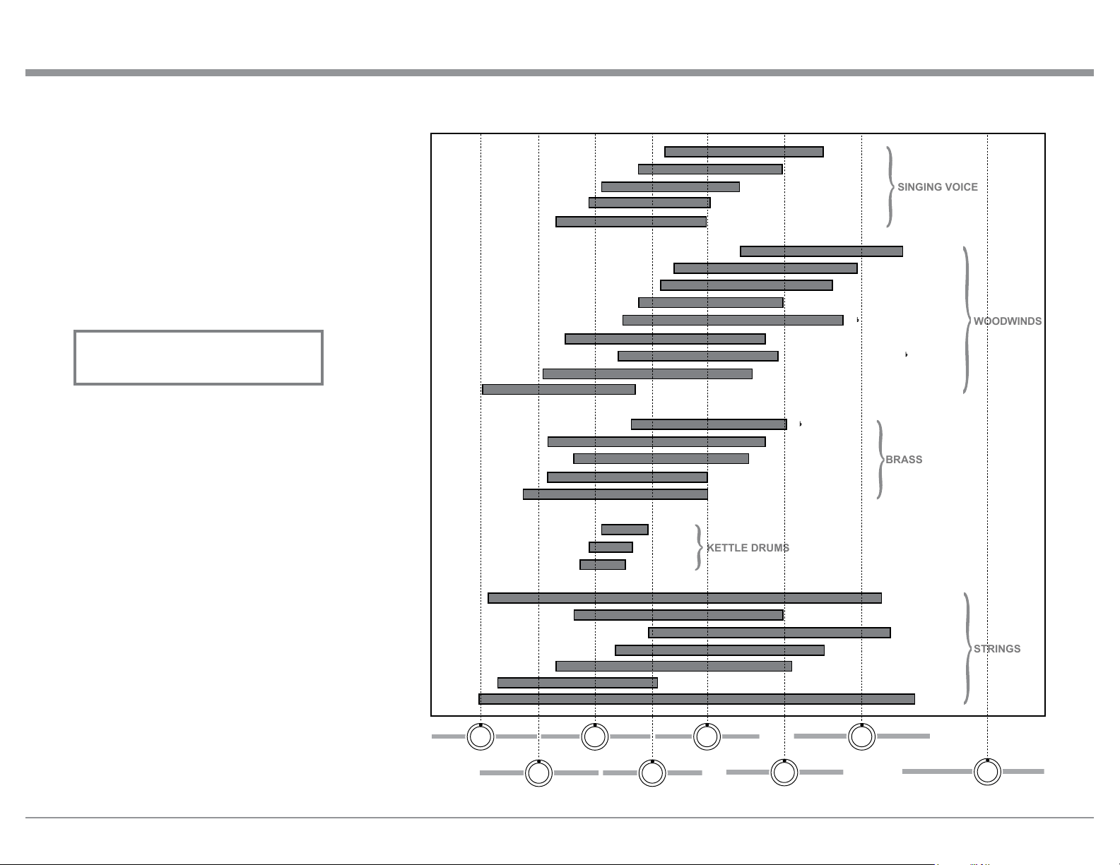
29
How to Operate the MA9000, con’t
the Remote Control, the BLUE (Setup) Push-button
followed by pressing the OUTPUT 2 Push-button to
switch On or Off the external Power Amplifier.
Passthru
When the MA9000 is connected together with a Mc-
Intosh Multichannel A/V Control Center or Surround
Decoder and has the PASSTHRU Mode activated, it
will automatically turn-on when the A/V Processor or
Surround Decoder is turned On. It will indicate on the
Front Panel Display “PASSTHRU”. Refer to figure 75.
The MA9000 OUTPUT 1 / OUTPUT 2 Front Panel
Push-buttons are active when in the Passthru Mode.
The other Front Panel Controls and Push-buttons are
deactivated as long as the Passthru Mode is active.
Equalizer Controls
The MA9000 Equalizer has eight Frequency Controls
which will raise or lower by 12dB, the amplitude of
the band of frequencies centered at the frequency
marked above the controls. The center frequencies
of these controls are at 25Hz, 50Hz, 100Hz, 200Hz,
400Hz, 1,000Hz, 2,500Hz and 10,000Hz. Both Left
and Right Channels are affected. At the center detent
or flat position of the controls, the tone circuit compo-
nents are removed from the signal path.
The illustration to the right shows the fundamental
frequency range of acoustical musical instruments and
the human voice. It also shows the range of adjustment
of frequencies for each of the Equalizer Controls of
the MA9000 at the +6dB and -6dB points.
Figure 75
PASSTHRU
Fundamental Frequencies of Acoustical Musical Instruments and the Human Voice
SOPRANO
CONTRALTO
TENOR
BARITONE
BASS
PICCOLO
FLUTE
OBOE
ENGLISH HORN
B CLARINET
BASS CLARINET
ALTO SAXOPHONE IN B
BASSOON
CONTRABASSOON
B TRUMPET
FRENCH HORN IN F
TENOR TROMBONE
BASS TROMBONE IN F
TUBA
MEDIUM
SMALL
LARGE
HARP
GUITAR
VIOLIN
VIOLA
CELLO
BASS
PIANO
STRINGS
KETTLE DRUMS
BRASS
WOODWINDS
SINGING VOICE
50Hz
200Hz
1kHz
10kHz
25Hz
100Hz
400Hz
2.5kHz
30
USB Input Operation and Driver Installation
The MA9000 USB Input provides the capability to
playback music from a computer, when the computer
is connected to the rear panel USB connector.
Note: The USB Input is for direct connection to a com-
puter only. To playback music from an USB Drive,
connect the USB Drive to another USB Port on
the computer and select the USB Drive with the
Media Playback Program.
The MA9000 USB Input is compatible with PC
Computers using Microsoft®, Windows 7 (SP1), Win-
dows 8.1 and Windows 10. It is also compatible with
Apple® Macintosh® Computers using OS-10.6.8 or
later.
When using a PC Computer with Windows, a spe-
cial McIntosh USB Audio Software Driver needs to be
installed on the PC Computer. The driver needs to be
installed before connecting the MA9000 USB Input to
the USB Port on the computer.
Note: If an Apple Macintosh computer is used with the
MA9000, no additional driver is required.
The McIntosh USB Audio Windows Driver is
available for download from the McIntosh Web Site:
http://www.mcintoshlabs.com/us/Support/Pages/
Manuals.aspx
Under “PRODUCT CATEGORY” select “Pre-
amplifiers” then under “MODEL NUMBER” select
“MA9000”. Click on “SEARCH” then select “Mc-
Intosh-HD USB Audio Windows Drive D v1.0” and
download the PC Windows Driver. Follow the instruc-
tions below to install the McIntosh MA9000 Driver:
Purpose: To Install the McIntosh
USB Audio Windows Driver for use with
McIntosh Products with an USB-Digital
Audio Input.
Requirements: 1. A PC Computer with a functioning
USB Port.
2. Windows 7 (SP1 or greater),
Windows 8 (8.1) or Windows 10
Operating System.
3. An USB Cable with Type A to
Type B Connectors.
Installing the Software
It is important to first install the downloaded software
on your computer before connecting the McIntosh
Product to the computer. The USB Driver is included
in the downloaded software package.
Note: Before installing this software, please check to see
if the McIntosh Product(s) with the USB-Digital
Audio Input has the latest firmware version, if not
update the firmware first.
1. Unzip the downloaded McIntosh Windows USB
Driver Software Package.
2. Run
“McIntoshHDSwPkg _20150814_v1p9p110p2.
zip”
. Refer to figures 90 thru 97.
How to Operate the MA9000, con’t
Figure 90
Figure 91
Figure 92
Figure 93
Figure 77
COAX 1 30%
______
Figure 76
COAX 1 30%
48kHz
Optical and Coaxial Digital Inputs
When a Digital Input (Optical or Coaxial Connection)
on the MA9000 is selected, the Front Panel Display
will indicate the sample rate when a signal is present
“48kHz”. Refer to figure 76.
During the time there is no Digital Signal present on
the selected input the display will indicate “______”.
Refer to figure 77.

31
How to Operate the MA9000, con’t
Figure 98
Figure 99
Figure 100
Figure 94
Figure 95
Figure 96
Figure 97
3. When the Windows Security window appears
check the
Always trust software from “Savitech
Cor p.”
box and then the Install button. When the
software has been installed, it is neces-
sary to reboot the computer. Refer to
figure 96.
After rebooting, a McIntosh-HD icon will
appear on the desktop. Refer to figure 98.
USB Connection
Connect the USB Cable with Type A to Type B con-
nectors between the PC Computer and the McIntosh
Product with the USB-Digital Audio Input. An Icon
will appear On-Screen indicating Windows has found
new hardware. Refer to
figure 99.
Upon completion of in-
stalling the driver, figure
100 will appear.
Figure 101
Figure 103
Figure 102
Figure 104
Windows Sound Settings
For proper operation of the McIntosh Product via the
Computer USB Connection, it is required to make
changes to Windows Sound Settings:
1. From the Windows
START button, click on
“CONTROL PANEL”
followed by selecting
“SOUND”. Refer to
figure 101.
2. Referring to figure 102,
first select “McIntosh-
HD HS USB Audio” and
than click on the “Set
Default” button.
Notes: 1. When the McIn-
tosh USB Audio
Product is not
connected to
your computer,
the previous
default Audio
Device will be
selected.
2. If other McIn-
tosh Products with USB Audio Connections
are also connected to the computer, an ad-
ditional “McIntosh USB Audio” playback
device will appear in the listing. Make
sure to select the “McIntosh-HD HS USB
Audio” from available playback devices
listed when using this McIntosh Product
for USB Audio.
Control Panel Settings
To activate the McIntosh-HD USB Audio Control Pan-
el Click on the “McIntosh Icon” (located in the Win-
dows notification area on the right side of the taskbar)
or Click on the Windows “Show hidden icons”, then
Select the “McIntosh Icon”. Refer to figures 103 and
104.
Notes: 1. It is not necessary
for the McIntosh-
HD USB Audio
Control Panel to
be running, unless
it is desired to
make changes to
the default set-
tings.
2. The McIntosh-
HD USB Audio
Control Panel
displays the cur-
rent Sampling
Rate, Bit-Rate
and Buffer Size
for the music
streaming from
the com-
puter into the
MA9000.
3. When the Media
Stream Program
on the computer
is set to output
in the “ASIO”
format, the Mc-
Intosh -HD USB
Audio Control
Panel allows for
changing the set-
tings parameters
on the fly.
32
Figure 105
USB 46%
44.1kHz
Figure 106
USB
51%
352.8kHz
Figure 107
USB
46%
DSD128
Figure 108
USB
51%
DSD256
USB Music Playback
When the USB Input is selected on the McIntosh
MA9000, the Front Panel Display indicates the
Sampling Rate (refer to figures 105 and 106 for PCM
Signals).
Figures 107 and 108 indicate a Sampling Rate of 128
or 256 times the Sampling Rate of a CD Disc for the
incoming DSD Digital Audio Signal.
The Sampling Rate and the Bit Rate are determined
by the original recording, the Application Output
Format (when available) and the McIntosh-HD Control
Panel Settings.
Note: In general, when the original music is recorded
at a higher Sampling Rate, the result is usually
more detail in the music. However, this higher
rate results in consuming larger amounts of stor-
age space. The Sample Rate usually should be set
to match the Sample Rate of the music recording
being played back.
There are many third party Applications (besides Ap-
plications like Windows Media Player) for steaming
music from the computer to McIntosh MA9000 USB
Input. An example of just one of the available applica-
tions is “JRiver Media Center”.
How to Operate the MA9000, con’t
How to Operate the MA9000, con’t
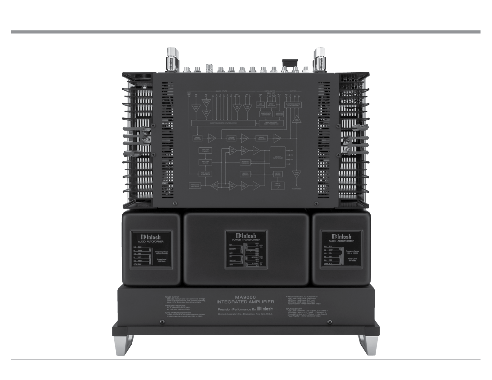
33
Photos
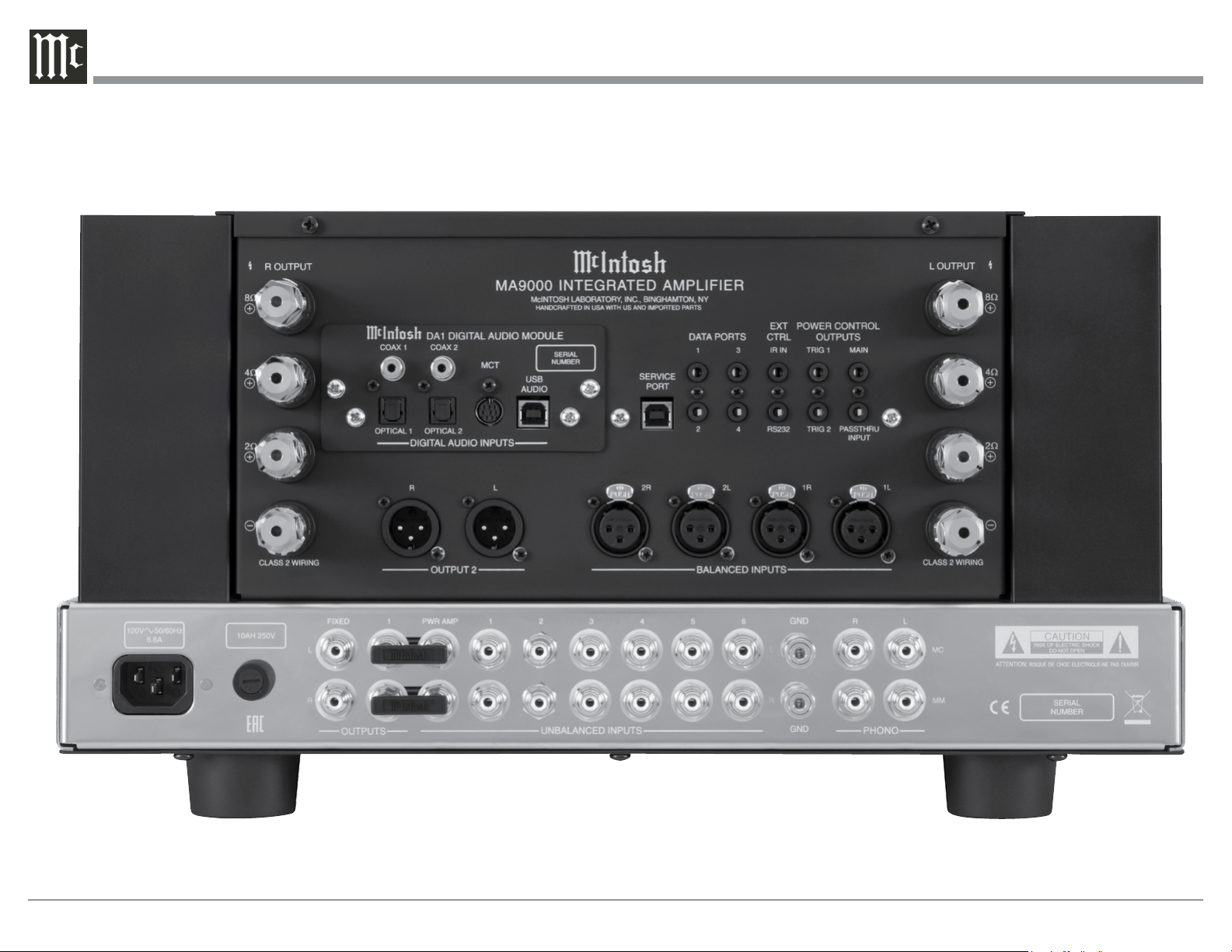
34
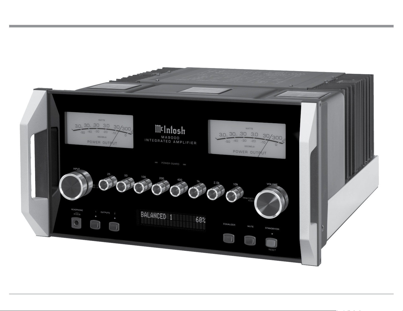
35
Photos
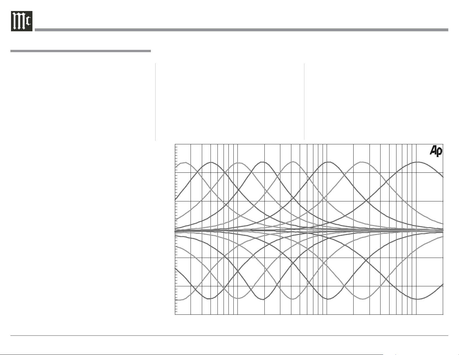
36
Preamplifier Specifications
Total Harmonic Distortion
0.005% maximum 20Hz to 20,000Hz
Intermodulation Distortion
0.005% maximum for any combination of frequencies
from 20Hz to 20,000Hz
Frequency Response
+0, -0.5dB from 20Hz to 20,000Hz
+0, -3dB from 10Hz to 100,000Hz
Preamplifier Output 1 and 2 (for rated input)
1.7V unbalanced (8V Maximum)
3.4V balanced (8V Maximum)
Preamplifier Output Impedance
220 ohms
Sensitivity (for rated output)
High Level - 300mV unbalanced
600mV balanced
Phono MM, 3.0mV
Phono MC, 0.3mV
Signal To Noise Ratio (A-Weighted)
High Level, 98dB below rated output
Phono MM, 84dB below 5mV input
Phono MC, 82dB below 0.5mV input
Input Impedance
High Level - 22K ohms Unbalanced
44k ohms Balanced
Phono MM - 50 to 400pF, in 50pF steps;
47K ohms
Phono MC - 50, 100, 200, 400 or 1,000 ohms;
100pF
Volt age Gain
High Level to Rec Output: 0dB
High Level to Output 1 and 2: 15dB
Phono MM to Rec Output: 40dB
Phono MC to Rec Output: 60dB
Phono MM to Output 1 and 2: 55dB
Phono MC to Output 1 and 2: 75dB
Maximum Input Signal
High Level, 8V unbalanced, 16V balanced
Phono MM, 80mV
Phono MC, 8mV
Headphone Impedance
100 to 600 ohms
Equalizer Controls
25Hz, 50Hz, 100Hz, 200Hz, 400Hz, 1,000Hz,
2,500Hz and 10,000Hz
20 50 100 200 500 1k 2k 5k 10k 20k
FREQUENCY IN HERTZ
0
- 5
A
M
P
L
I
T
U
D
E
I
N
D
E
C
I
B
E
L
S
-10
-15
+ 5
+10
+15

37
Power Amplifier Specifications
Power Output
Minimum sine wave continuous average power output
per channel, with both channels operating is:
300 watts into 2 ohm load
300 watts into 4 ohm load
300 watts into 8 ohm load
Output Load Impedance
2, 4 or 8 ohms
Rated Power Band
20Hz to 20,000Hz
Total Harmonic Distortion
0.005% maximum with both channels operating from
250 milliwatts to rated power, 20Hz to 20,000Hz
Intermodulation Distortion
0.005% maximum, if the instantaneous peak power
output does not exceed twice the rated power output
for any combination of frequencies from 20Hz to
20,000Hz.
Dynamic Headroom
1.8dB
Wide Band Damping Factor
Greater than 40
Power Guard
Less than 2% THD with up to 16dB overdrive at
1,000Hz
Frequency Response
+0, -0.25dB from 20Hz to 20,000Hz
+0, -3.0dB from 10Hz to 100,000Hz
Input Sensitivity (for rated output)
1.7 Volts
Signal To Noise Ratio (A-Weighted)
114dB below rated outpu)
Input Impedance
22,000 ohms
Maximum Input Signal
Power Amplifier In, 16V
Volt age Gain
29dB, 8 Ohms
26dB, 4 Ohms
23dB, 2 Ohms
MA9000 Preamplifier, Digital Audio and Power Amplifier Specifications
Digital Audio Specifications
Digital Input Signal Format
Coaxial and Optical Inputs - SPDIF (PCM)
MCT and USB Inputs - PCM, DSD
Digital Input Sample Rate
Coaxial and Optical: 44.1kHz to 192kHz, 24-Bit
MCT: 44.1kHz, 16-Bit (CD)
DSD64 (SACD)
USB: 44.1kHz to 384kHz, 32-Bit (PCM)
DSD64, DSD128, DSD256,
DXD352.8kHz, DXD384kHz
Digital Inputs
Coaxial: 0.5V p-p/75 ohms
Optical: -15dbm to -21dbm (TOS Link)
MCT: 0.5V p-p/75 ohms
USB: USB Type B Connector
38
General Specifications
Power Control and Trigger Output
12VDC, 25mA
Power Requirements
Field AC Voltage conversion of the MA9000 is not
possible. The MA9000 is factory configured for one
of the following AC Voltages:
100 Volts, 50/60Hz at 8.0 amps
110 Volts, 50/60Hz at 6.6 amps
120 Volts, 50/60Hz at 6.6 amps
127 Volts, 50/60Hz at 6.6 Amps
220 Volts, 50/60Hz at 3.6 amps
230 Volts, 50/60Hz at 3.3 amps
240 Volts, 50/60Hz at 3.3 amps
Standby: Less than 0.25 watt
Note: Refer to the rear panel of the MA9000 for the cor-
rect voltage.
Overall Dimensions
Width is 17-1/2 inches (44.45cm)
Height is 9-7/16 inches (24.0cm) including feet
Depth is 22 inches (55.88cm) including the Front
Panel, Knobs and Cables
Weight
101 pounds (45.8 kg) net, 134 pounds (60.8 kg) in ship-
ping carton
Shipping Carton Dimensions
Width is 29-1/2 inches (74.93cm)
Depth is 29 inches (73.66cm)
Height is 17 inches (43.18cm)
MA9000 General Specifications
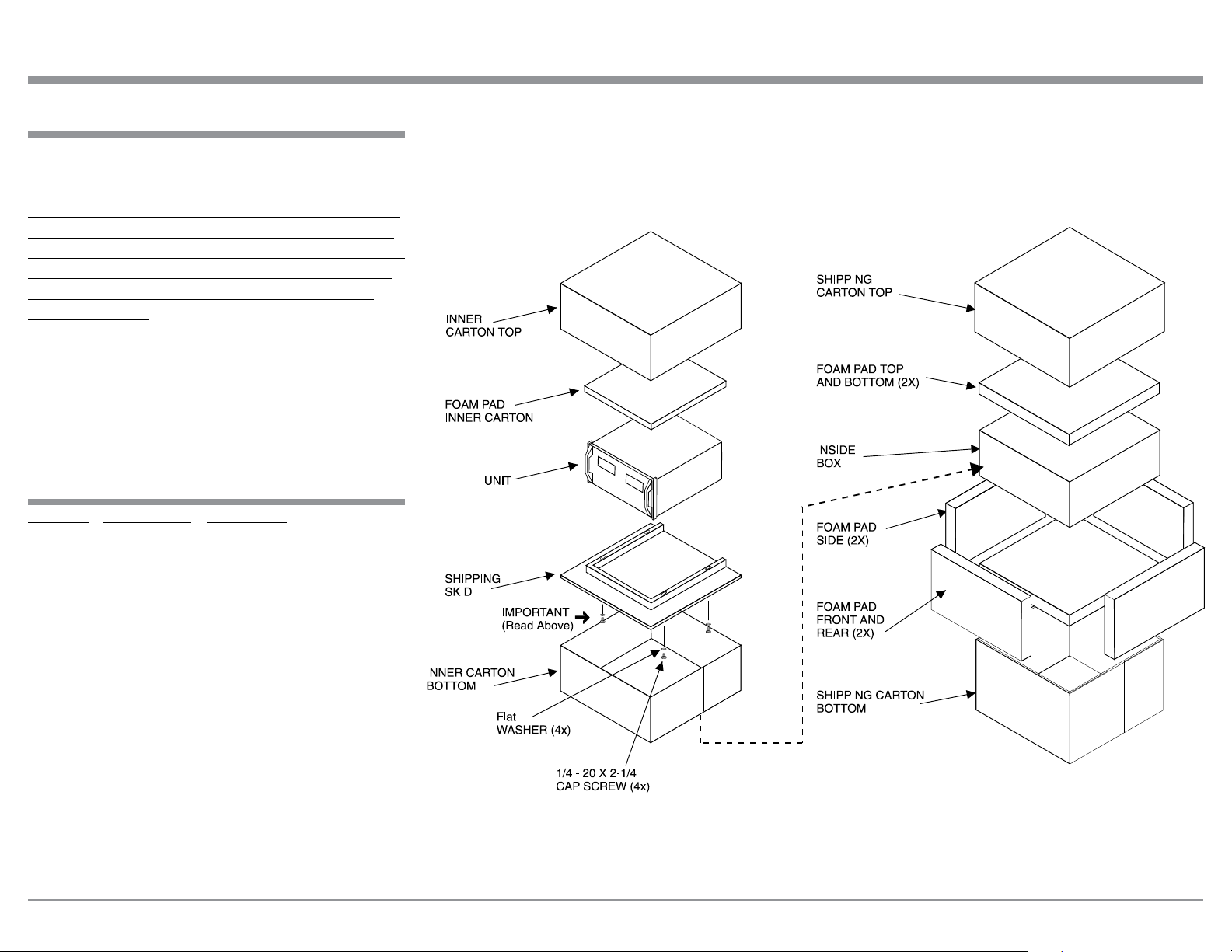
39
Packing Instructions
Packing Instructions
MA9000 Packing Material List
In the event it is necessary to repack the equipment for
shipment, the equipment must be packed exactly as
shown below. It is very important that the four plastic
feet are attached to the bottom of the equipment. Two
1/4-20 x 2-1/4 inch screws and washers must be used
to fasten the unit securely to the bottom pad and wood
skid. This will ensure the proper equipment location
on the bottom pad. Failure to do this will result in
shipping damage.
Use the original shipping carton and interior parts
only if they are all in good serviceable condition. If
a shipping carton or any of the interior part(s) are
needed, please call or write Customer Service Depart-
ment of McIntosh Laboratory. Refer to page 2. Please
see the Part List for the correct part numbers.
Quantity Part Number Description
1 034052 Shipping carton top
1 034051 Shipping carton bottom
2 034186 Front and rear foam pad
2 034187 Side foam pad
2 034054 Top and bottom foam pad
1 034136 Inner carton top
1 034137 Inner carton bottom
1 034188 Inner foam pad
1 034479 Shipping skid
4 401212 1/4-20 hex cap x 2-1/4 inch
screw
2 104058 1/4 inch flat washer 1-1/2
inch
4 017937 Plastic foot
4 404080 #10 flat washer

The continuous improvement of its products is the
policy of McIntosh Laboratory Incorporated who
reserve the right to improve design without notice.
Printed in the U.S.A.
McIntosh Laboratory, Inc.
2 Chambers Street
Binghamton, NY 13903
www.mcintoshlabs.com
McIntosh Part No. 04175401