McIntosh Laboratory, Inc. 2 Chambers Street Binghamton, New York 13903-2699 Phone: 607-723-3512 www.mcintoshlabs.com
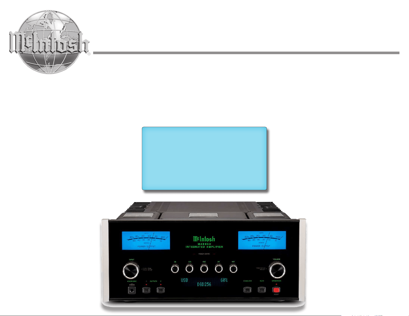
MA8950
Integrated Amplifier
Owner's Manual

2
FCC Information (For US Customers)
1. IMPORTANT NOTICE:
DO NOT MODIFY THIS PRODUCT
This product, when installed as indicated in the instructions
contained in this manual, meets FCC requirements. Modication
not expressly approved by McIntosh may void your authority,
granted by the FCC, to use the product.
2. CAUTION:
• To comply with FCC RF exposure compliance requirement,
separation distance of at least 20cm must be maintained between
this product and all persons.
• This product and its antenna must not be co-located or
operating in conjunction with any other antenna or transmitter.
3. COMPLIANCE INFORMATION:
• Product Name: Integrated Turntable
• Model Number: MTI100
• This product contains FCC ID: SSS-BC11X:
McIntosh Laboratory, Inc.
2 Chambers Street
Binghamton, NY 13903
Tel. (607) 723-3512
IC Information (For Canadian Customers)
1. PRODUCT:
This product contains IC : 11012A-BC11X
This product complies with RSS-210 of Industry Canada.
Operation is subject to the following two conditions: (1) this
product may not cause harmful interference, and (2) this product
must accept any interference received, including interference
that may cause undesired operation. This Class B digital
apparatus complies with Canadian ICES-003.
2. CAUTION:
To reduce potential radio interference to other users, the
antenna type and its gain should be so chosen that the equivalent
isotropically radiated power (e.i.r.p.) is not more than that
permitted for successful communication.
Informations sur IC (pour les clients Canadiens)
1. A PPA R EI L:
Cet appareil contiens IC : 11012A-BC11X
Cet appareil est conforme à la norme CNR-210 du Canada.
L’utilisation de ce dispositif est autorisée seulement aux deux
conditions suivantes : (1) il ne doit pas produire de brouillage,
et (2) l’utilisateur du dispositif doit être prêt à accepter tout
brouillage radioélectrique reçu, même si ce brouillage est
susceptible de compromettre le fonctionnement du dispositif.
Cet appareil numérique de la classe B est conforme à la norme
Important Safety Information is supplied in a separate document “Important Additional Operation Information Guide
”
NMB-003 du Canada.
2. ATTENTION:
An de réduire le risque d’interférence aux autres
utilisateurs, il faut choisir le type d’antenne et son gain de façon
à ce que la puissance isotrope rayonnée
équivalente (p.i.r.e.) ne soit pas supérieure au niveau requis pour
l’obtention d’une communication satisfaisante.
Canadian Customers:
CAN ICES-003 (B)/NMB-003 (B)
RF Exposure Information
This equipment complies with FCC/IC radiation exposure limits
set forth for an uncontrolled environment and meets the FCC
radio frequency (RF) Exposure Guidelines in Supplement C to
OET65 and RSS-102 of the IC radio frequency (RF) Exposure
rules. This equipment has very low levels of RF energy that are
deemed to comply without testing of specic absorption ratio
(SAR).
Cet équipement est conforme aux normes d’exposition aux
radiations FCC/IC dénies pour un environnement non contrôlé
et satisfait les directives d’exposition à la radiofréquence
(RF) dans le supplément C des OET65 et RSS-102 des règles
d’exposition à la fréquence radio (RF) IC. Cet équipement a de
très faibles niveaux d’énergie RF qui sont jugés conformes sans
test de taux d’absorption spécique (SAR).
R&TTE(EN) Information
1. DECLARATION OF CONFORMITY
Our products follow the provisions of EC/EU directives:
LV: 2006/95/EU
EMC: 2014/30/EU
RoHS: 2011/65/EU
ErP: EC regulation 1275/2008 and its frame work
directive 2009/125/EC
2. IMPORTANT NOTICE:
DO NOT MODIFY THIS PRODUCT
This product, when installed as indicated in the instructions
contained in this manual, meets R&TTE directive requirements.
Modication of the product could result in hazardous Radio and
EMC radiation.
3. CAUTION:
Separation distance of at least 20cm must be maintained between
this product and all persons.
This product and its antenna must not be co-located or operating
in conjunction with any other antenna or transmitter.
Before You Begin, Read This!
We understand that you're eager to get started using
your McIntosh, but to make sure you have the best
possible experience up front, we highly recommend
taking some time to thoroughly read through this
manual and any included documentation. This will
help to answer any questions you may have and make
sure you stay safe and don't run into any issues that
will prevent you from getting started quickly.
We have designed this manual to make sure your
excitement doesn't wane by the time you fire up
your unit. Experienced McIntosh users will find this
manual as a valuable reference, while newer users will
find it comprehensive enough to get started smoothly
and effectively. As you read through the manual, you
will find that everything is laid out intuitively, and
everything is written succinctly and efficiently. We
want you to spend less time reading, and more time
listening.
If you are an experienced user and are confident in
your ability to quickly get started on your own, you
will find connection diagrams on Page 6 to help guide
you along.
You are absolutely free to reach out to us to ask any
questions or provide feedback about any aspect of
your McIntosh experience. You can reach us via the
contact information on the next page.

3
Thank you from all of us at McIntosh
You have invested in a precision instrument that will
provide you with many years of enjoyment. For the
best experience and your safety, please be sure to heed
and comply with the instructions and warnings found
throughout the included documentation.
If you need further technical assistance, please contact
your dealer who may be more familiar with your
particular setup including other brands. You can also
contact McIntosh with additional questions or in the
unlikely event of needing service.
McIntosh Laboratory, Inc.
2 Chambers Street
Binghamton, New York 13903
Technical Assistance: ..(607) 723-3512
Fax: ............................(607) 724-0549
Customer Service: ......(607) 723-3515
Fax: ............................(607) 723-1917
Email: .....[email protected]
Website: ................ mcintoshlabs.com
Make a Note
For future reference, you can jot down your serial
number and purchase information here. We can
identify your purchase from this information if the
occasion should arise.
Serial Number:
Purchase Date:
Dealer Name
Copyright 2021 © by McIntosh Laboratory, Inc
Contents
Trademark and License Information .................... 4
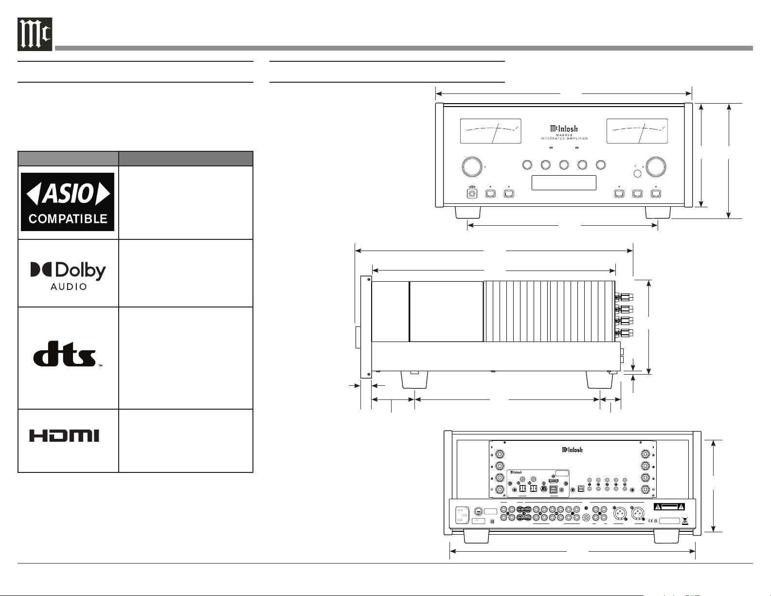
Dimensions ............................................................... 4
Instal lation ............................................................... 5
Connecting Devices (Diagrams) ............................ 6
Input and Control: ................................................ 6
Output and Loudspeakers: ................................... 7
Navigating the Rear Panel ...................................... 8
Connector and Cable Information ........................ 9
Connecting Loudspeakers ...................................... 10
Preparing the Output Terminal Posts: ................. 10
Preparing Your Speaker Wire: ............................ 10
Connecting Speakers (Bare Wire): ..................... 10
Connecting Speakers (Banana Plug): ................. 10
Connecting Speakers (Spade Lug): ..................... 10
Navigating the Front Panel .................................... 11
Navigating the Remote Control ............................. 12
Setting Up Your MA8950 ....................................... 13
Using Knobs for Menu Navigation: ..................... 13
Entering Setup Menu: ..................................... 13
Entering Trim Functions Menu: ...................... 13
Selecting/Adjusting Menu Settings: ................. 13
Exiting/Navigating Back: ................................ 13
The Setup Menu: .................................................. 13
Input Settings: ................................................. 13
Output Settings: .............................................. 13
Power Control Triggers Settings: ................... 14
Data Ports Settings: ........................................ 14
Passthru Settings: ........................................... 14
HDMI CEC Settings: ....................................... 14
HDMI Lip Sync Mode Settings: ...................... 14
Digital Gain Settings: ..................................... 14
USB Automute Settings: .................................. 14
Comm Port Baud Rate Settings: ..................... 14
IR Codes Settings: ........................................... 14
IR Sensor Settings: .......................................... 15
Power Saving Settings: ................................... 15
Factory Reset: ................................................. 15
Using Your MA8950 ............................................... 15
Powering On/Turning Off: .................................. 15
Selecting an Input for Playback: ......................... 15
Adjusting the Volume: ........................................ 15
Adjusting Trim Functions: ................................... 15
Adjusting Audio Balance: ............................... 15
Enabling/Disabling the Equalizer:.................. 15
Adjusting Input Trim Levels: ........................... 15
Adjusting Phono Resistance (Turntables): ...... 15
Toggling Stereo/Mono: .................................... 15
Toggling the Meter Backlights: ....................... 15
Adjusting Display Brightness: ........................ 15
Enabling/Disabling HXD: ............................... 15
Muting the Audio: ............................................... 15
Getting the Most Out of Your MA8950 ................ 16
Using the Autoformer: ......................................... 16
Using the Five-Band Equalizer: ........................... 16
Using Bi-Amplification on Loudspeakers: .......... 16
Using the HXD with Headphones: ...................... 16
Listening Worry-Free (Auto Protection): ............. 16
Using the Onboard Power Amplifier: .................. 16
Using External Power Amplifiers: ....................... 16
Using MA8950 with External Amp: ................. 16
Using Only External Amps:............................. 16
Using Audio Passthru: ......................................... 16
Viewing Coax/Optical Inputs Sample Rate: ........ 16
Using USB Playback: ........................................... 16
Installing the Software: ................................... 17
Frequently Asked Questions .................................. 17
Amplifier Specifications ......................................... 18
Digital Audio Specifications................................... 18
General Specifications ............................................ 19
Packing Instructions ............................................... 19
MA8950 Packing Material List ............................. 19
4
POWE R GUA RD
1
2OUTP UTS
EQUA LIZER MUTE STANDB Y/ON
INP UT
HEAD PHONE
RESE T
PUSH - T RIM
HOLD - S ETUP
TRIM S ETUP/
ADJU ST
30 125 500 2k 10 k
VOL UME
FUSE
PUSH
R OUTPUT
8Ω
4Ω
2Ω
8Ω
4Ω
2Ω
L OUTPUT
DATA PORTS
3
1
4
2
IR IN
RS232
EXT
CTRL
MAIN
TRIG 1
TRIG 2
MA8950 INTEGRATED AMPLIFIER
McINTOSH LABORATORY, INC., BINGHAMTON, NY
HANDCRAFTED IN USA WITH US AND IMPORTED PARTS
POWER CONTROL
OUTPUTS
PASSTHRU
INPUT
SERVICE
PORT
CLASS 2
WIRI
NG CLASS 2
WIRI
NG
2
L
R
FIXED
1
PWR AMP 1 2 3 4 5
GND
6
R
MC
MM
L
R
L
CAUTION
RISK OF ELECTRIC SHOCK
DO NOT OPEN
SERIAL
NUMBER
120V 50/60Hz
4.4A
T 6.3AL 250V
UNBALANCED
INPUTS
PHONO BALANCED
OUTPUTS
USB AUDIO
DA2 DIGITAL AUDIO MODULE
HDMI (ARC)
COAX 2
COAX 1
MCT
OPTICAL 2OPTICAL 1
DIGITAL AUDIO INPUTS
SERIAL
NUMBER
Trademark and License Information
The McIntosh MA8950 incorporates copyright
protected technology that is protected by U.S. patents
and other intellectual property rights. The MA8950
uses the following Technologies:
Trademark License Information
ASIO is a trademark and
software of Steinberg Media
Technologies GmbH
Manufactured under license
from Dolby Laboratories.
Dolby, Dolby Audio, and the
double-D symbol are trade-
marks of Dolby Laboratories.
For DTS patents, see http://
patents.dts.com. Manufactured
under license from DTS, Inc.
DTS, the Symbol, DTS and
the Symbol together, and
Digital Surround are registered
trademarks and/or trademarks
of DTS, Inc. in the United
States and/or other countries.
DTS, Inc. All Rights Reserved.
The terms HDMI, HDMI
High-Definition Multimedia
Interface, and the HDMI Logo
are trademarks or registered
trademarks of HDMI Licensing
Administrator, Inc.
HIGH-DEFINITION MULTIMEDIA INTERFACE
TM
POWE R GUA RD
1
2OUTP UTS
EQUA LIZER MUTE STANDB Y/ON
INP UT
HEAD PHONE
RESE T
USB 35%
DSD256
PUSH - T RIM
HOLD - S ETUP
TRIM S ETUP/
ADJU ST
30 125 500 2k 10 k
VOL UME
22..00mm
2200 mm
..22 00
22.. 00
2200
2200 00
-- 44 00
-- 33 00
-- 22 00
-- 11 00
00
-- 55 00
DECIBELS
WATTS
POWER OUTPUT
22..00mm
2200 mm
..22 00
22.. 00
2200
2200 00
-- 44 00
-- 33 00
-- 22 00
-- 11 00
00
-- 55 00
DECIBELS
WATTS
POWER OUTPUT
FUSE
PUSH
R OUTPUT
8Ω
4Ω
2Ω
8Ω
4Ω
2Ω
L OUTPUT
DATA PORTS
3
1
4
2
IR IN
RS232
EXT
CTRL
MAIN
TRIG 1
TRIG 2
MA8950 INTEGRATED AMPLIFIER
McINTOSH LABORATORY, INC., BINGHAMTON, NY
HANDCRAFTED IN USA WITH US AND IMPORTED PARTS
POWER CONTROL
OUTPUTS
PASSTHRU
INPUT
SERVICE
PORT
CLASS 2
WIRI
NG CLASS 2
WIRI
NG
2
L
R
FIXED
1
PWR AMP 1 2 3 4 5
GND
6
R
MC
MM
L
R
L
CAUTION
RISK OF ELECTRIC SHOCK
DO NOT OPEN
SERIAL
NUMBER
120V 50/60Hz
4.4A
T 6.3AL 250V
UNBALANCED
INPUTS
PHONO BALANCED
OUTPUTS
USB AUDIO
DA2 DIGITAL AUDIO MODULE
HDMI (ARC)
COAX 2
COAX 1
MCT
OPTICAL 2OPTICAL 1
DIGITAL AUDIO INPUTS
SERIAL
NUMBER
17-1/2"
44.5cm
7-1/8"
18.1cm
7-5/8"
19.4cm
18-3/4"
47.6 cm
29/32"
1.8cm
3/16"
0.5cm
6-1/4"
15.9cm
13"
33cm
1-5/8"
4.1cm
1"
2.5cm
16-3/4"
42.5cm
6"
15.2cm
12-3/16"
31cm
Front View:
Side View:
Dimensions
16-1/2"
41.9cm
Rear View:
5
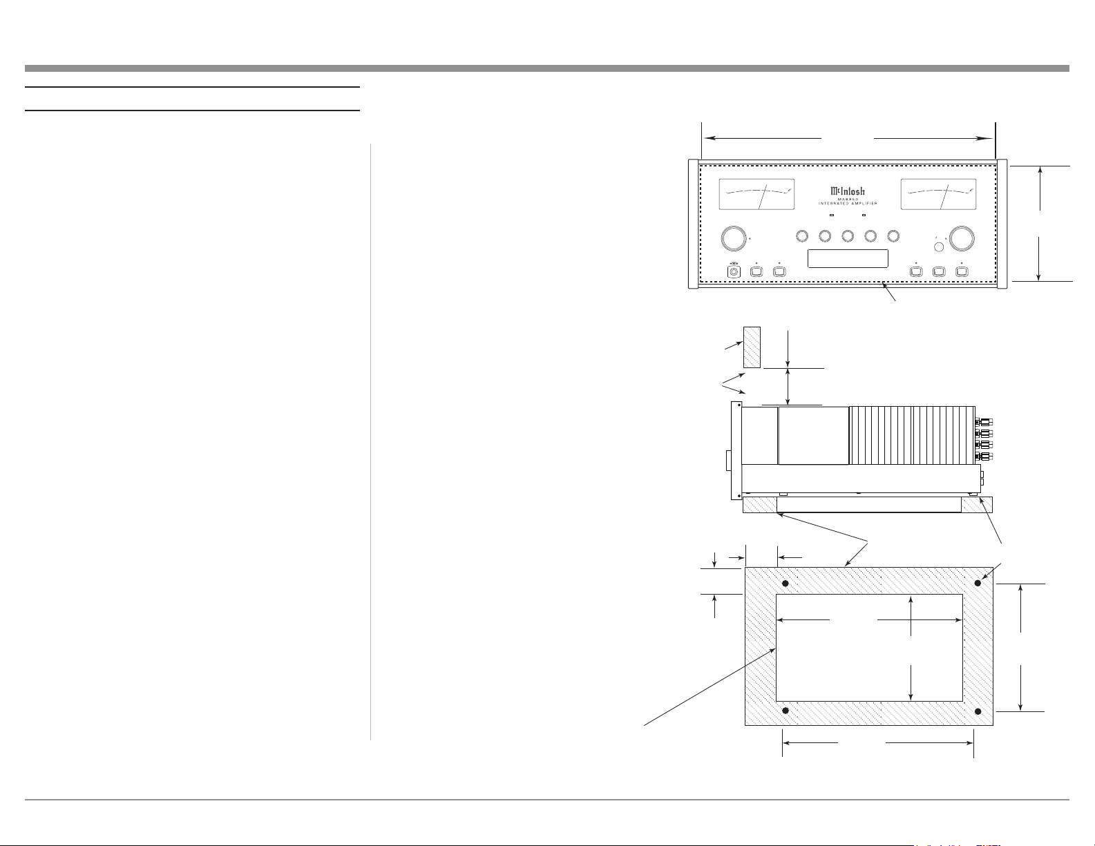
Installation
WA R NI NG: The MA8950 is heavy (approx. 75 lbs).
Please get help when moving the unit, and
make sure your furniture or cabinetry is sturdy
enough to hold it.
The MA8950 can be placed upright on a table or shelf,
standing on its four feet. It also can be custom installed in
a piece of furniture or cabinet of your choice. The four feet
may be removed from the bottom of the MA8950 when it is
custom installed as outlined below. The four feet together
with the mounting screws should be retained for possible
future use if the MA8950 is removed from the custom
installation and used free standing. The required panel
cutout, ventilation cutout and unit dimensions are shown.
Always provide adequate ventilation for your MA8950.
Cool operation ensures the longest possible operating life
for any electronic instrument. Do not install the MA8950
directly above a heat generating component such as a high
powered amplifier. If all the components are installed in
a single cabinet, a quiet running ventilation fan can be a
definite asset in maintaining all the system components at
the coolest possible operating temperature.
A custom cabinet installation should provide the following
minimum spacing dimensions for cool operation.
Allow at least 6 inches (15.24cm) above the top, 2 inches
(5.08cm) below the bottom and 2 inches (5.1cm) on each
side of the Integrated Amplifier, so that airflow is not
obstructed. Allow 20 inches (50.8cm) depth behind the
front panel. Allow 1-7/6 inch (3.66cm) in front of the
mounting panel for Knob clearance. Be sure to cut out a
ventilation hole in the mounting shelf according to the
dimensions in the drawing.
Notes:
1. If you remove the feet from your unit, be sure not
to lose them, as they will need to be reattached if
you need to send the unit back for service.
2. Use an appropriately-sized Phillips drill bit,
or you may cause damage to the screw heads,
making the feet impossible to remove.
POWE R GUAR D
1
2OUTP UTS
EQUA LIZER MUTE STANDB Y/ON
INPU T
HEAD PHONE
RESE T
USB 35%
DSD256
PUSH - TR IM
HOLD - SE TUP
TRIM SE TUP/
ADJUS T
30 125 500 2k 10 k
VOLU ME
22..00mm
22 00 mm
..2200
22 ..00
22 00
22 00 00
--4400
--3300
--2200
--1100
00
--5500
DECIBELS
WATTS
POWER OUTPUT
22..00mm
22 00 mm
..2200
22 ..00
22 00
22 00 00
--4400
--3300
--2200
--1100
00
--5500
DECIBELS
WATTS
POWER OUTPUT
6 -5/8"
16.83cm
17-1/16"
43.34cm
Cutout Opening for Custom Mounting
MA8900 Front Panel
Custom Cabinet Cutout
Cutout
Opening
for
Ventilation
Cutout Opening for Ventilation
Support
Shelf
Cabinet
Front
Panel
Chassis
Spacers
MA8900 Side View
in Custom Cabinet
MA8900 Bottom View
in Custom Cabinet
14-1/2"
36.8cm
1"
2.5cm
6"
15.2cm
Opening
for Ventilation
13"
33cm
15-1/16"
38.3cm
2"
5.1cm
Note: Center the cutout Horizontally
on the unit. For purposes of
clarity, the above illustration
is not drawn to scale.
13-5/16"
33.8cm
MA8950 Front Panel
Custom Cabinet Cutout
MA8950 Side View
in Custom Cabinet
MA8950 Bottom View
in Custom Cabinet
6
WLAN ANT 1
WLAN ANT 2
FUSE
PUSH
R OUTPUT
8Ω
4Ω
2Ω
8Ω
4Ω
2Ω
L OUTPUT
DATA PORTS
3
1
4
2
IR IN
RS232
EXT
CTRL
MAIN
TRIG 1
TRIG 2
MA8950 INTEGRATED AMPLIFIER
McINTOSH LABORATORY, INC., BINGHAMTON, NY
HANDCRAFTED IN USA WITH US AND IMPORTED PARTS
POWER CONTROL
OUTPUTS
PASSTHRU
INPUT
SERVICE
PORT
CLASS 2 WIRING CLASS 2 WIRING
2
L
R
FIXED
1
PWR AMP 1 2 3 4 5
GND
6
R
MC
MM
L
R
L
CAUTION
RISK OF ELECTRIC SHOCK
DO NOT OPEN
SERIAL
NUMBER
120V 50/60Hz
4.4A
T 6.3AL 250V
UNBALANCED
INPUTS
PHONO BALANCED
OUTPUTS
USB AUDIO
DA2 DIGITAL AUDIO MODULE
HDMI (ARC)
COAX 2
COAX 1
MCT
OPTICAL 2OPTICAL 1
DIGITAL AUDIO INPUTS
SERIAL
NUMBER
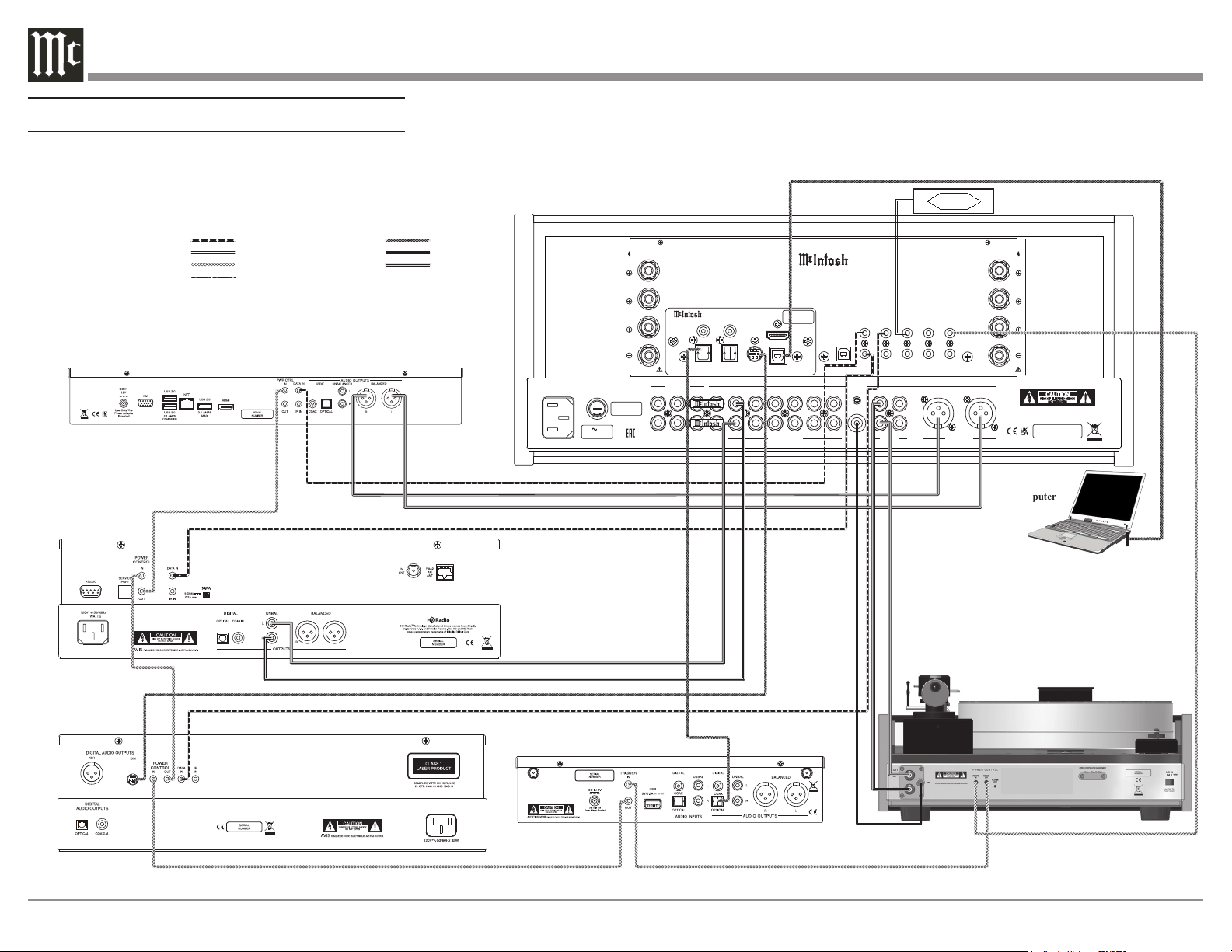
Turntable
IR Sensor
Computer
AM/FM Tuner
30
Media Server
SACD/CD Transport
Digital Audio Player
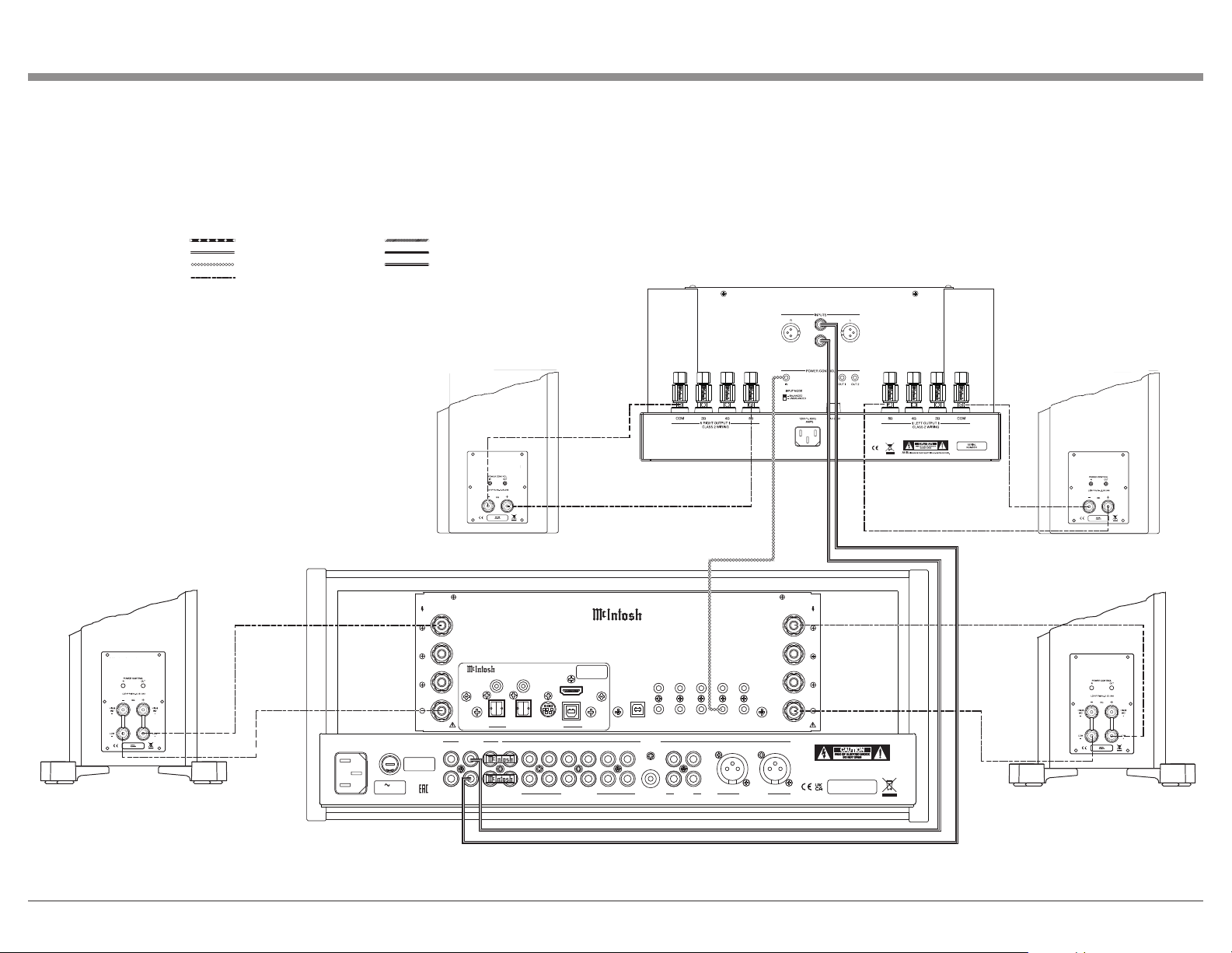
Connection Legend:
Data Cable*
Digital Signal Cable
Sensor/Keypad Cable Ground Wire
Power Control Cable* Audio Signal Cable
Loudspeaker Cable
* 2 conductor shielded with 1/8 inch stereo mini phone plug on each end.
MA8950 Connection Diagram - Input and Control
Connecting Devices (Diagrams)
Input and Control:
7
6.6
FUSE
PUSH
R OUTPUT
8Ω
4Ω
2Ω
8Ω
4Ω
2Ω
L OUTPUT
DATA PORTS
3
1
4
2
IR IN
RS232
EXT
CTRL
MAIN
TRIG 1
TRIG 2
MA8950 INTEGRATED AMPLIFIER
McINTOSH LABORATORY, INC., BINGHAMTON, NY
HANDCRAFTED IN USA WITH US AND IMPORTED PARTS
POWER CONTROL
OUTPUTS
PASSTHRU
INPUT
SERVICE
PORT
CLASS 2
WIRI
NG CLASS 2
WIRI
NG
2
L
R
FIXED
1
PWR AMP 1 2 3 4 5
GND
6
R
MC
MM
L
R
L
CAUTION
RISK OF ELECTRIC SHOCK
DO NOT OPEN
SERIAL
NUMBER
120V 50/60Hz
4.4A
T 6.3AL 250V
UNBALANCED
INPUTS
PHONO BALANCED
OUTPUTS
USB AUDIO
DA2 DIGITAL AUDIO MODULE
HDMI (ARC)
COAX 2
COAX 1
MCT
OPTICAL 2OPTICAL 1
DIGITAL AUDIO INPUTS
SERIAL
NUMBER
Power Amplifier - Secondary Room
Left Loudspeaker - Secondary RoomRight Loudspeaker - Secondary Room
Right Loudspeaker
Left Loudspeaker
+
-
+
-
+
-
+
-
Connection Legend:
Data Cable*
Digital Signal Cable
Sensor/Keypad Cable Ground Wire
Power Control Cable* Audio Signal Cable
Loudspeaker Cable
* 2 conductor shielded with 1/8 inch stereo mini phone plug on each end.
MA8950 Connection Diagram - Output and Loudspeaker
Output and Loudspeakers:
8
FUSE
PUSH
R OUTPUT
8Ω
4Ω
2Ω
8Ω
4Ω
2Ω
L OUTPUT
DATA PORTS
3
1
4
2
IR IN
RS232
EXT
CTRL
MAIN
TRIG 1
TRIG 2
MA8950 INTEGRATED AMPLIFIER
McINTOSH LABORATORY, INC., BINGHAMTON, NY
HANDCRAFTED IN USA WITH US AND IMPORTED PARTS
POWER CONTROL
OUTPUTS
PASSTHRU
INPUT
SERVICE
PORT
CLASS 2
WIRI
NG CLASS 2
WIRI
NG
2
L
R
FIXED
1
PWR AMP 1 2 3 4 5
GND
6
R
MC
MM
L
R
L
CAUTION
RISK OF ELECTRIC SHOCK
DO NOT OPEN
SERIAL
NUMBER
120V 50/60Hz
4.4A
T 6.3AL 250V
UNBALANCED
INPUTS
PHONO BALANCED
OUTPUTS
USB AUDIO
DA2 DIGITAL AUDIO MODULE
HDMI (ARC)
COAX 2
COAX 1
MCT
OPTICAL 2OPTICAL 1
DIGITAL AUDIO INPUTS
SERIAL
NUMBER
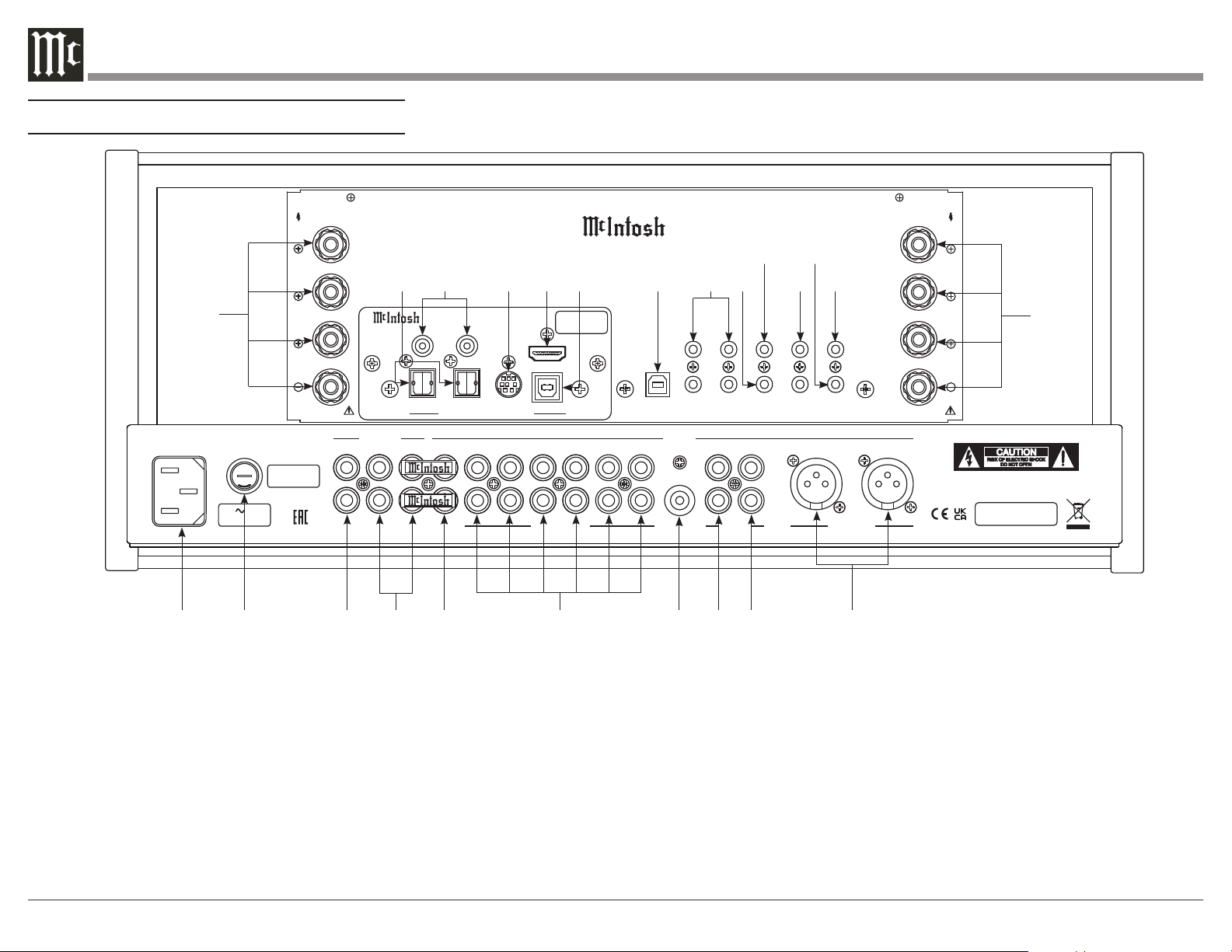
1. Main Power: Attach the included power cable here.
2. Main Fuse Holder: This is where the main fuse to
power the unit is located.
3. Fixed Outputs: An RCA connector cable will
produce a fixed, non-adjustable Volume level signal
from here.
4. Outputs (1 and 2): Use these ports with an RCA
cable to send the signals to a subwoofer or power
amplifier. Connect included Jumper Plugs (see next
page) to Output 1 and PWR AMP to use onboard amp
(see Page 16).
5. PWR AMP Input: The included Jumper Plugs (see
next page) connect Output 1 to the onboard power
amplifier (see Page 16). Also used as a loop for room
correction with Outputs 1 and 2.
6. Unbalanced Inputs (1-6): You can connect up
to six high-level unbalanced signals using an RCA
connection with these ports.
7. GND Input: This is where you would put a ground
wire from a turntable to prevent noise.
8. MC Phono Input: A turntable with a moving coil
cartridge will plug in here with an RCA cable.
9. MM Phono Input: A turntable with a moving
magnet cartridge will plug in here with an RCA cable.
10. Balanced Inputs: Plug in an XLR connector cable
(see next page) to these ports for balanced signals.
11. Loudspeaker Output Terminal Posts: Connect
loudspeakers to these posts (see Page 10).
12. Optical Inputs (1 and 2): These ports accept
optical connections for digital signals.
13. Coax Inputs (1 and 2): You will connect coaxial
cables for digital signals into these ports.
Navigating the Rear Panel
1
2
3
4 5
6
7 8
9
10
11
12
13 14
15
16
17
18
19
20
21
22
11
23
9
14. MCT Input: Used to transfer signals from
McIntosh products with an MCT connector. Required
for SACD audio.
15. HDMI (ARC) Input: Connect an HDMI cord
here to share control and connectivity with a compat-
ible ARC TV.
Note: The HDMI ARC functionality of the MA8950
is only compatiable with ARC TVs. Other
devices will not work.
16. USB Audio Input: A USB Type-B connector will
go here to receive a digital signal from a computer.
17. Service Port: This USB Type-B port will be used
for service purposes only.
18. Data Ports (1-4): Using 3.5mm data cables (see
next section), you can plug other McIntosh devices
into these ports and control them with your McIntosh
Remote Control.
19. RS232 Port: Using a 3.5mm-to-DB9 cable
(see next section), you can connect the device to a
computer or another controller device through here.
20. IR In Port: Connect an external IR sensor here
with a 3.5mm connector (see next section).
21. Trigger Ports (1 and 2): Connecting external
components to these ports via a 3.5mm connection
(see next section) will allow you to send a signal to
turn those devices On or Off from a signal sent by the
MA8950.
22. Passthru Input: Connecting other devices with
a 3.5mm connector (see next section), in addition to
their main connection, will enable Passthru Mode
when enabled in the Setup Menu (see Page 13),
producing unaltered audio.
23. Main Output Control Port: McIntosh devices
can turn each other On and Off when connected via a
3.5mm connector (see next section) to these ports.
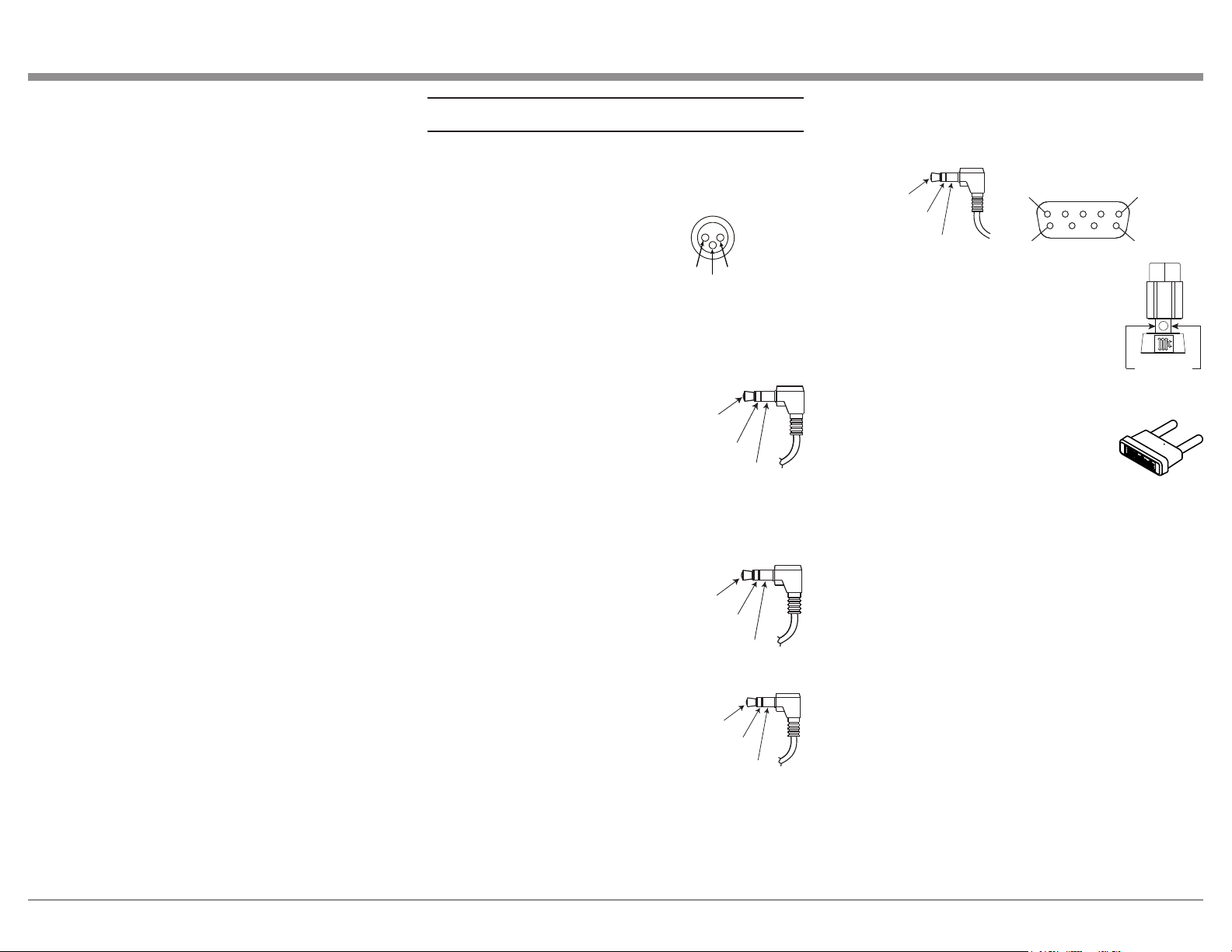
Connector and Cable Information
XLR Connectors
Below is the Pin configuration for the XLR Balanced
Input Connectors on the MA8950. Refer to the dia-
gram for connection:
PIN 1: Shield/Ground
PIN 2: + Output
PIN 3: - Output
Power Control and Trigger Connectors
The Power Control Trigger Output Jacks send and
Passthru Input Jack receives Power
On/Off Signals (+12 volt/0 volt)
when connected to other McIntosh
Components. An additional connec-
tion is for controlling the illumina-
tion of the Power Output Meters
on McIntosh Power Amplifiers. A
3.5mm stereo mini phone plug is
used for connection to the Power Control, Trigger and
Passthru Outputs.
Data Port Connectors
The Data Out Ports send Remote
Control Signals to Source Compo-
nents. A 3.5mm stereo mini phone
plug is used for connection.
IR IN Port Connectors
The IR IN Port also uses a 3.5mm
stereo mini phone plug and allows
the connection of other brand IR
Receivers to the MA8950.
RS232-C Data Port Cable
The RS232 Data Cable is a 3.5mm stereo mini phone
plug to a sub miniature DB 9 connector:
Output Terminal Connector
When cables with spade lugs are used
for Loudspeaker Connection, the spade
lugs need an opening of at least 3/10 inch
(7.6m m)
McIntosh Plug-In Jumper Connector
(x2 Included)
The MA8950 utilizes two phono style
Plug-In Jumpers to connect the Preampli-
fier Output to the Power Amplifier Input.
Note: Additional or replacement Jumper Connectors can
be obtained from the McInotsh Parts Department
under Part No. 117781.
PIN 1
PIN 2
PIN 3
Power
Control
Meter
Illumination
Control
Ground
Main, Trig 1&2
and Pass-Thru
Data
Signal
N/C
Data
Ground
IR Data
Control
Ground
N/C
PIN 1
PIN 6
PIN 5
PIN 9
Data In
(DB9-pin2)
Ground
(DB9-pin5)
Data Out
(DB9-pin3)
DB9
(male connector)
3/10 of an inch
(7.6millimeters)
10
Connecting Loudspeakers
WA R NI NG: To avoid injury due to electrical shock
or damage to your unit, do not attempt to attach
loudspeakers while the MA8950 is plugged into
a power outlet.
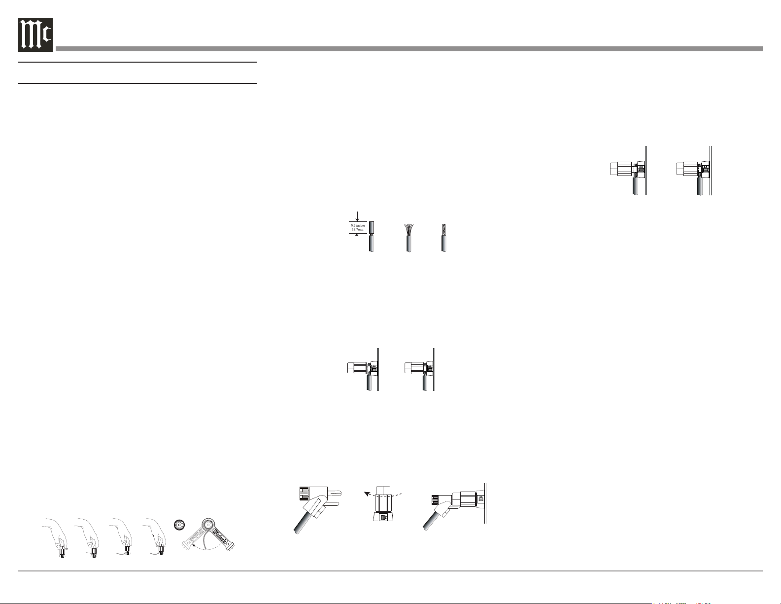
Preparing the Output Terminal Posts:
Notes:
1. When attaching loudspeakers, make sure
the wires you used for positive (+) polarity
are connected between the matching positive
connectors on both the speakers and the unit. Do
the same for the wires you used for negative (-)
polarity. Do not make a connection between the
separate channels (left and right).
2. Refer to your speakers’ documentation to
determine the correct Output Terminal Post to
connect them to based on their ohm impedance.
If your speaker ohm impedance falls between
the MA8950s labeled Output Terminal Posts, use
the nearest lower connection. Example: If your
speakers have a 6-ohm impedance, connect them
to the 4-ohm Output Terminal Post.
3. If you’re using banana plugs, loosening the
Output Terminal Posts is not necessary. Make
sure the posts are tight before you attach the
banana plugs.
To prepare the Output Terminal Posts for wires,
unscrew them with your fingers counterclockwise
until the opening on the post is exposed. When wires
are set inside, tighten by turning the posts clockwise
until they stop, making sure not to overtighten*.
Finally, to secure the wires in place, use the included
McIntosh Wrench and turn the posts one quarter turn
(90°) clockwise.
*WA R NI NG: Overtightening can cause damage.
Opening
Preparing Your Speaker Wire:
Your speaker cord will have two sections, each with a
set of wires in casing – one for each polarity (positive
and negative). Using your choice of tool (such as pliers
or clippers), take one cord section from one end and
gently cut away and remove about ½ inch of the outer
casing, making sure not to cut the internal wires. Once
the casing is removed and the wires are exposed, use
your fingers to twist the wires together until they are
as narrow as possible, resembling a screw. Repeat this
process for the remaining sections on both ends of the
speaker cord.
Connecting Speakers (Bare Wire):
After loosening the Output Terminal Posts, you
will see an opening. Place your narrowed wires you
previously exposed through the opening and tighten
the posts using the method described in “Preparing
the Output Terminal Posts” on this page.
Connecting Speakers (Banana Plug):
Make sure the Output Terminal Posts are tightened
via the method described in “Preparing the Output
Terminal Posts” (if necessary) and connect the banana
plugs into the holes of the appropriate posts.
Figure F
Figure G
Figure H
Figure L
Figure M
Connecting Speakers (Spade Lug):
While the Output Terminal Posts are unscrewed, slip
the openings of the forks of the spade lugs around the
inner part of the posts. and tighten the posts using the
method described in “Preparing and Tightening the
Output Terminal Posts”.
.
Figure I
Figure J
Figure K
Figure L
Figure M
11
POWER GUARD
1
2OUTPUTS
EQUALIZER MUTE STANDBY/ON
INPUT
HEADPHONE
RESET
USB 35%
DSD256
PUSH - TRIM
HOLD - SETUP
TRIM SETUP/
ADJUST
30 125 500 2k 10k
VOLUME
22..00mm
2200mm
..2200
22.. 00
2200
220000
-- 44 00
-- 33 00
-- 22 00
-- 11 00
00
-- 55 00
DE C I BE L S
WAT T S
P O W E R O U T P U T
22..00mm
2200mm
..2200
22.. 00
2200
220000
-- 44 00
-- 33 00
-- 22 00
-- 11 00
00
-- 55 00
DE C I BE L S
WAT T S
P O W E R O U T P U T
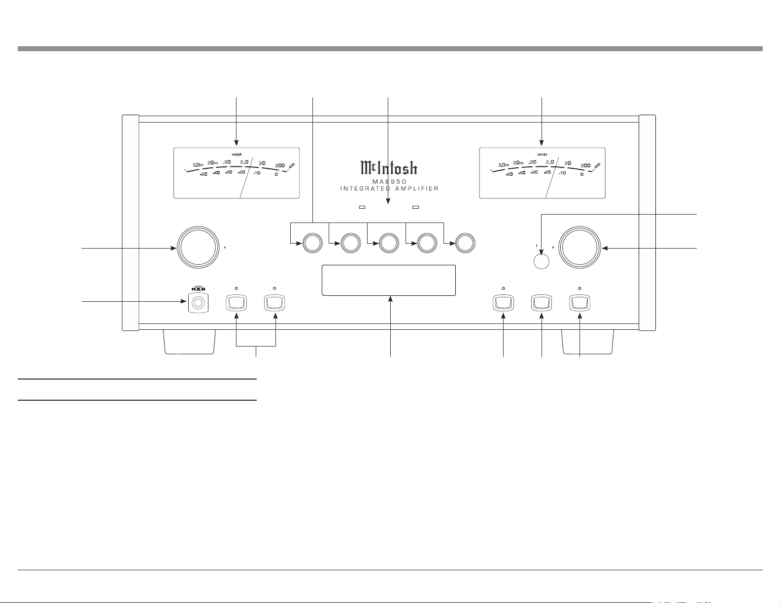
Navigating the Front Panel
1. Input Control Knob: Rotate this to select different
Input sources for playback, as well as navigate through
different options in the menus. Access menus by
holding or pressing the Knob in (see Page 13).
2. Headphone Jack: Plug in your .25” headphones
here to gain access to the headphone amplifier.
3. Outputs Toggle Buttons (1 and 2): You can toggle
playback through the outputs using these buttons.
4. Information Display: This will show information
based on your current selection. Shows inputs and
Menu options for navigation.
5. Equalizer Toggle Button: Toggle the Equalizer
(see Page 16) On or Off for the currently selected
Input with this button.
6. Mute Button: This will mute all audio playback
from the MA8950.
7. Standby/On Button: You can turn the device On or
Off - put it in Standby Mode - using this button.
8. Volume Knob: Adjust the Volume with this Knob.
You will also use this to adjust Settings in the menus
(see Page 13).
9. IR Sensor: This is how the MA8950 receives
commands from your Remote Control.
10. Power Output Meters: These gauge the power
Output from the amplifier channels.
11. Frequency Adjustment Knobs: These will
adjust the frequencies marked above each Knob for
the sound coming through the any Input that has the
Equalizer (see Page 16) is activated.
12. Power Guard Lights: These LED lights will
illuminate when McIntosh’s patented Power Guard
(see Page 16) automatically kicks on to prevent
playback distortion and protect your system from
damage.
1
2
3 4 5 6
7
8
9
10
1011 12
12
1
2
3
4
5
6
7
8
9
10
11
12
13 14
15
16
17
18
19
21
20
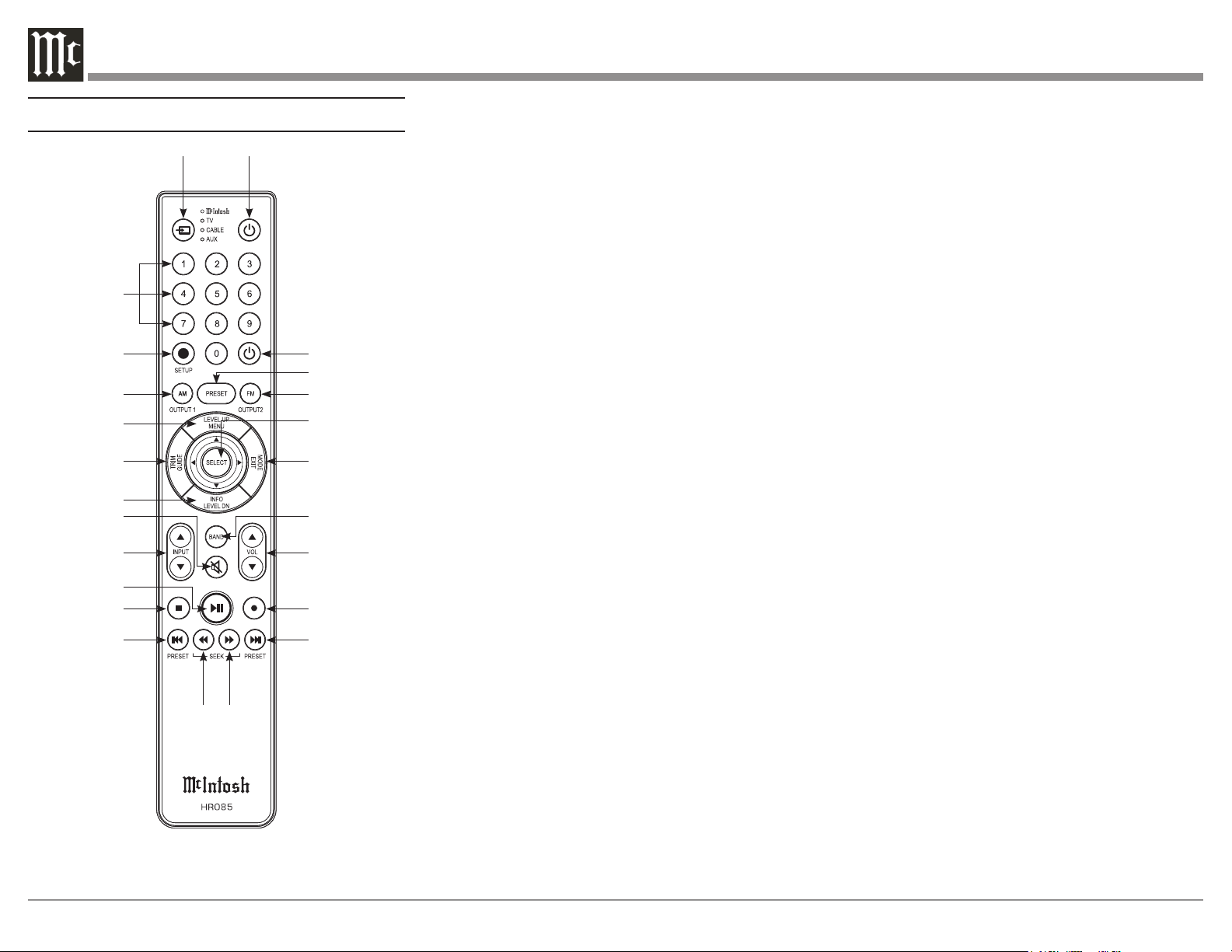
Navigating the Remote Control
Note: The included McIntosh HR085 Remote
Control has buttons used to control multiple
devices. While operating the MA8950 with
the Remote, nothing will happen when press-
ing buttons that activate features not present
on the MA8950. Refer to HR085 Owner's
Manual on www.mcintoshlabs.com.
1. Switch Device: Select different devices for Remote
operation. Selected device is indicated by the LED
light when buttons are pressed.
2. Numbers: You can select tuner presets and
manually enter disc tracks and radio stations – among
other numerical functions – using these buttons.
3. Setup: The Setup Button gives you access to the
additional functions for the buttons represented in
blue text. It’s like using the “Shift” key on a keyboard
to access special characters above the number keys.
(Note: Cannot be used to enter Setup Mode.)
4. AM Tuner/Output 1: Access AM Tuner or press
Setup followed by this button to toggle Output 1.
5. Level Up/Menu: Adjusts Trim Functions Settings
(see Page 15). Accesses Menu on compatible devices.
6. Trim/Guide: Enters Trim Functions Menu (see
Page 15). Opens guide on compatible devices.
7. Info/Level Down: Adjusts Trim Functions Settings
(see Page 15). Accesses info on compatible devices.
8. Mute: Mutes audio playback.
9. Input: Changes and selects different inputs.
10. Play/Pause: Pressing this button will halt playback
of active media, and it will resume from where it left
off if you press the button again.
11. Stop: Cancels media playback and resets progress
through it.
22
23
24
12. Previous/Previous Preset: You can go back to
your previous media selection by pressing this button.
Also allows you to navigate to a previous tuner preset.
13. Fast Reverse/Seek Down: Navigate backwards
through the current active media using this button.
This is also used to adjust the tuner downwards.
14. Fast Forward/Seek Up: Navigate forward through
the current active media using this button. This is also
used to adjust the tuner upwards.
15. Next/Next Preset: You can go forward to your
next media selection by pressing this button. Also
allows you to navigate to a later tuner preset.
16. Record: On devices with a record function, this
will begin recording the actively playing media.
17. Volume: Adjust the Volume with these buttons.
18. Band: You will have the option to change the band
on your connected tuner or select certain options on a
variety of McIntosh models.
19. Mode/Exit: This will exit the Trim Functions
Menu (see Page 15). It will also display information or
certain options.
20. Select: Where applicable, you can press this
button to select any highlighted option.
21. FM Tuner/Output 2: Access FM Tuner or press
Setup followed by this button to toggle Output 2.
22. Preset: Press this button followed by a number
(0-9) to immediately select that stored preset.
23. Power Off: Whichever device you have selected
on the Remote Control will turn Off when you press
this button.
24. Power On: Whichever device you have selected
on the Remote Control will turn On when you press
this button.

13
Setting Up Your MA8950
Using Knobs for Menu Navigation:
In addition to their normal use, you will use the Input
Control Knob and the Volume Knob to enter the
Menu, navigate through the selections, and adjust the
different Settings options.
Entering Setup Menu:
To enter the Setup Menu, hold the Input Control Knob.
Once the Display shows the unit model, the firmware
version, and the serial number, release the Knob and
you are in the Setup Menu. See next section for the
Setup Menu overview.
Note: "Enter Code" will appear if the Input Control
Knob is held too long. This is for support
purposes only. Press the Knob again to exit.
Entering Trim Functions Menu:
A brief deliberate press (not hold) and release of
the Input Control Knob will take you to the Trim
Functions Menu. See Page 15 for the Trim Functions
over view.
Selecting/Adjusting Menu Settings:
You can navigate through and select the different
options in the menus by rotating the Input Control
Knob. To adjust a selected Setting, use the Volume
Knob. If a category in a Menu has a Submenu avail-
able, the Display will show “Hold Input”, allowing you
to hold down the Input Control Knob to see additional
options.
Exiting/Navigating Back:
A brief deliberate press (not hold) and release of the
Input Control Knob will exit the current Menu. Make
additional presses until the Display shows the main
operating screen to continue normal use of the unit.
Output Settings:
SETUP: Outputs
(Hold Input)
↓
SETUP: [ Output 1, Output 2 ]
[ Switched, Unswitched ]
Switched: The front panel/Remote Control Output
buttons will function as normal, allowing you to
toggle On and Off the outputs.
Unswitched: The front panel/Remote Control Output
buttons will be deactivated and the outputs will be
always On.
SETUP: HEADPHONES
[ Mute All Outputs, Mute No Outputs ]
Mute All Outputs: When headphones are plugged in,
mute audio from all other outputs and play audio from
the headphones exclusively.
Mute No Outputs: When headphones are plugged in,
continue to play audio through other outputs as normal
in addition to the audio from the headphones.
The Setup Menu:
See the previous section for instructions on entering,
navigating, and adjusting Settings in the Setup Menu.
The following is a list of the available Settings
options in the Setup Menu as they will appear on your
Display. A down arrow ↓ represents being taken to a
Submenu after holding the Input Control Knob while
the Display says "Hold Input". The selectable options
will be listed in brackets [ ] and separated by commas,
with a brief description underneath of what each
option does when selected.
Input Settings:
SETUP: Inputs
(Hold Input)
↓
SETUP: [ input name ]
[ On / Rename, Off ]
On / Rename: The selected Input will be functioning
as normal. Hold in the Input Control Knob to enter the
Menu to rename the Input*.
Off: The selected Input will be deactivated and
will no longer be selectable from the Main Display
during normal use. Change this Setting back to “On /
Rename” to make it selectable again.
*Renaming Inputs: While in this inputs Submenu,
use the Input Control Knob to navigate to the Input
with the name you’d like to change (and turn it On
using the Volume Knob if it isn’t already) so that the
Display says "SETUP: [ input name ] On / Rename"
and hold the Input Control Knob to begin renaming.
The character you are currently adjusting will be
blinking. Rotate the Input Control Knob to select
which character you want to change and use the
Volume Knob to change the character.
14
Digital Gain Settings:
SETUP: Digital Gain
(Hold Input)
↓
SETUP: [HDMI, OPTI 1, OPTI 2] Gain
[ Volume in dB ]
To get more even playback Volume from your
connected digital devices, adjust their individual
volumes with this Setting. The defaults are +15dB for
HDMI and +0dB for Optical.
USB Automute Settings:
SETUP: USB Automute
[ On/Off ]
On: Mutes USB playback for the first half of a second
to prevent the audible "noise burst" that sometimes
occurs when switching digital files or signals.
Off: USB playback will not be muted when switching
digital files or signals.
Comm Port Baud Rate Settings:
SETUP: RS232
[ rate in bits ] Baud
The speed at which the MA8950 communicates with
devices plugged into the Comm Port (the Baud Rate)
can be adjusted with this Setting. It is recommended
to leave this at the highest Setting of 115200.
IR Codes Settings:
SETUP: IR Codes
[ Normal, Alternate ]
By default, the included HR085 Remote Control sends
"Normal" IR codes when buttons are pressed. Any
McIntosh device set to receive "Normal" IR codes
will receive the signal. To prevent controlling multiple
devices with the Remote at once, change this Setting
to "Alternate" to prevent signals from the Remote
being read. You can also set the Remote itself to send
"Alternate" codes. Refer to the HR085 manual on the
McIntosh website for instructions on how to do so.
Power Control Triggers Settings:
SETUP: Triggers
(Hold Input)
↓
SETUP: [ TRIGGER 1, TRIGGER 2 ]
[ Main, Output 1, Output 2, Input (Hold Input) ]
Main: An On/Off signal is sent to devices attached to
the TRIG 1 and TRIG 2 ports when the MA8950 is
turned On or Off.
Output 1: Turns On/Off any devices attached to either
TRIG 1 or TRIG 2 when Output 1 is activated, either
via the front panel buttons or the Remote Control.
Output 2: Turns On/Off any devices attached to either
TRIG 1 or TRIG 2 when Output 2 is activated, either
via the front panel buttons or the Remote Control.
SETUP: [ TRIGGER 1, TRIGGER 2 ]
[ Main, Output 1, Output 2, Input (Hold Input) ]
↓
SETUP: TRIGGER [ 1, 2 ]
[ input name ] : [ ON, OFF ]
[ input name ] : ON: Turns On/Off any devices
attached to TRIG 1 or TRIG 2 when the Input is
selected on the Main Display during normal use.
[ input name ] : OFF: Prevents any devices attached
to TRIG 1 or TRIG 2 from turning On/Off when the
Input is selected on the Main Display during normal
use.
Data Ports Settings:
SETUP: Data Ports
(Hold Input)
↓
SETUP: [ DATA PORT (1-4) ]
[ All Data, input name ]
All Data: Devices connected to all four data ports
will receive the same data from the Remote Control.
[ input name ]: Dedicate one of the data dorts to a
specific Input, forcing that data port to only send data
received from that Input when it receives commands
from the Remote Control.
Passthru Settings:
SET U P: PASST HRU
[ input name, Off ]
[ input name ]: Enables Passthru for the signal
received by the MA8950 from the selected Input,
which will bypass the onboard preamplifier and send
it straight to the onboard power amplifier without
altering it in any way.
Off: Disables Passthru, and the MA8950 will process
each Input signal as normal.
HDMI CEC Settings:
SETUP: HDMI CEC
[ ON, OFF ]
ON: Allows compatible devices to use CEC
(Consumer Electronics Control) to control certain
functions of the MA8950.
OFF: Prevents MA8950 from being controlled w/ CEC.
SETUP: HDMI CEC PWR
[ ON, OFF ]
ON: Allows compatible devices to use CEC
(Consumer Electronics Control) to power On/Off the
MA8950 or be powered On/Off by the MA8950.
OFF: Prevents devices from using CEC to power
On/Off the MA8950 or be powered On/Off by the
MA8950.
HDMI Lip Sync Mode Settings:
SETUP: Lip Sync Mode
[ Auto, Manual ]
Auto: The MA8950 will automatically synchronize
video and audio signals received through HDMI.
Manual: Disabled auto video/audio synchronization
through HDMI, allowing you to manually calibrate
audio/video sync from connected devices.
15
IR Sensor Settings:
SETUP: Front IR
[ Enabled, Disabled ]
You can enable or disable the functionality of the IR
sensor to change whether or not the MA8950 will
accept commands from the Remote Control. You may
want to do this if you have an external IR sensor that
operates the MA8950 with other devices.
Power Saving Settings:
SETUP: Auto-Off
[ Enabled, Disabled ]
Enabled: The MA8950 automatically enters Standby
Mode after approximately 30 minutes of inactivity.
Disabled: The MA8950 will not power Off automati-
cally and will remain On until you turn it Off.
Factory Reset:
FACTORY RESET
(Hold Input)
While on this option, hold the Input Control Knob
until the Display says "In Progress!" and immediately
release. Once the Display says "Completed!", your
unit's Settings will be set back to their factory
defaults.
Using Your MA8950
Note: In the unlikely event that your commands are no
longer being registered by the unit, you can try
resetting the microprocessors. To do so, hold the
Standby/On button down until the LED power
indicator light switches Off. Release the button,
and when the light illuminates again, you can
press the button again to power the unit On and
resume normal operation. This will also revert
the Settings to factory defaults. Be sure to let off
the button as soon as the LED lights back up.
Powering On/Turning Off:
While the unit is in Standby Mode (no lights except
the LED indicator light are On), press the Standby/On
front panel button to power On the unit. While the unit
is On, press the button to enter Standby Mode (turn it
Off). Using the Remote Control, press the Power On
and Power Off buttons where appropriate.
Selecting an Input for Playback:
You can change the current playback source by
rotating the Input Control Knob or by using the Input
Buttons on the Remote Control.
Adjusting the Volume:
Rotate the Volume Knob or use the Volume Buttons
on the Remote Control to adjust the Volume. The
current Volume level is represented by a percentage on
the Display. Note: The Volume control does not affect
audio through the Fixed Outputs.
Adjusting Trim Functions:
See Page 13 for instructions on entering, navigating,
and adjusting Settings in the Trim Function Menu.
The Remote Control will also adjust these Settings.
Note: The Balance, Input Trim, and Equalizer Settings
in this Menu will only be adjusted and affect the
currently selected Input and their configurations
will be independently saved.
The following is a list of descriptions of the various
options in the Trim Functions Menu.
Adjusting Audio Balance:
You may want one loudspeaker to be louder than the
other. While on the Balance Setting, use the Volume
Knob to adjust the meter to whichever channel you
wish to be louder. The more filled the meter is under
a channel, the louder that channel will get, while the
opposite channel will get quieter.
Enabling/Disabling the Equalizer:
Turning On the Equalizer will allow you to adjust
the sound frequency for the selected Input using the
Frequency Adjustment Knobs. Sound will adjust for
each Input that has it activated. Note: The Equalizer
does not affect audio through the Fixed Outputs..
Adjusting Input Trim Levels:
Devices connected to the various inputs may be
sending audio at varying volumes to the MA8950.
This could result in uneven playback Volume when
changing sources. To correct this, you can raise or
lower the Volume of an Input as it enters the MA8950
by adjusting its Trim level with this Setting.
Adjusting Phono Resistance (Turntables):
With the MC Phono source Input selected, the option
to change the phono resistance becomes available
in the Trim Functions Menu. Make sure to match
this number to your turntable’s recommended phono
resistance level.
Toggling Stereo/Mono:
Stereo allows the left and right channels to have
separate independent audio signals. Mono sends the
same signal through both channels. You can toggle
between the two with this Setting.
Toggling the Meter Backlights:
You can turn On/Off the illumination of the power
meters here.
Adjusting Display Brightness:
Use the Volume Knob to adjust the Brightness level of
the Display.
Enabling/Disabling HXD:
This option will become available if headphones
are plugged in. Enable this option to experience
McIntosh’s patented Headphone Crossfeed Director
(HXD) or disable it to have unaltered audio playback
through the headphones.
Muting the Audio:
Use the mute button on the front panel or the Remote
Control to mute the audio coming from the MA8950.

16
Getting the Most Out of Your MA8950
Using the Autoformer:
Your MA8950 comes equipped with independent
connectors specifically allocated for loudspeakers
of 2-, 4-, and 8-ohm impedance. Separating these
connections allows McIntosh to use its patented
Autoformer to provide the full 200 watts of power
regardless of your speakers’ specifications.
Using the Five-Band Equalizer:
As with all McIntosh products, your MA8950
produces the clearest, most accurate form possible
of any audio that pumps through it. If the audio sent
from the source is suboptimal, however, then the
“clearest, most accurate form” might not be ideal for
every situation. If you find yourself wanting to adjust
the audio frequencies, enable the Equalizer (with the
button on the front panel or in the Trim Functions
Menu) to activate the functionality of the five
Frequency Adjustment Knobs. Turning the knobs will
adjust from the low frequencies (30Hz) up to the high
frequencies (10,000Hz). Experiment with different
rotations of the knobs to produce your desired sound.
The Equalizer will affect the sound for any Input that
has it on, and its On/Off status will be saved per Input.
Using Bi-Amplification on Loudspeakers:
WA R NI NG: If the loudspeakers you are attempting
to connect for bi-amplification have Jumper
Plugs connecting the mid/high and low frequen-
cies, they must be removed before making the
connections to the amplifier(s). Failure to do so
may result in damage to your equipment.
The MA8950’s onboard power amplifier may be used
in conjunction with a separate external power ampli-
fier to connect a loudspeaker for bi-amplification,
allowing more flexible power control to the separate
mid/high and low frequencies of the loudspeaker. You
will do this by first removing the McIntosh Jumper
Plugs from the Output 1 ports and the PWR AMP
ports on the MA8950. In their place, bridge each of
the left and right channels of the Output 1 and PWR
AMP ports with a shielded RCA Y splitter. Connect
the open ends of each of the Y splitters to your
separate external power amplifier.
Using the HXD with Headphones:
Enable Headphone Crossfeed Director (HXD) to
improve the sound localization for your headphones.
HXD restores the directionality component of the
spatial sound stage, giving you the quality and
immersion of a loudspeaker paired with the privacy of
headphones.
Listening Worry-Free (Auto Protection):
The internal McIntosh Power Guard monitors and
adjusts sound waves at the speed of light, preventing
harsh sounding distortion and clipping that could
damage your speakers. The Power Guard LED lights
on the front panel will be lit when it automatically
activates. The MA8950 also includes an internal
Sentry Monitor, which guages the amount of incoming
electricity and will automatically protect your unit in
the event of improper current flow, allowing you to
listen while knowing your unit is safe.
Using the Onboard Power Amplifier:
To use the internal preamplifier and power amplifier
simultaneously, connect the Output 1 ports and the
PWR AMP ports using the included Jumper Plugs.
This audio will be produced through Output 1.
Using External Power Amplifiers:
While your MA8950 comes fully equipped with a
preamplifier and a power amplifier with the capability
of playing the crystal-clear audio you'd expect from
McIntosh amps through your loudspeakers, you have
the option to attach separate power amplifiers if you
so choose. You can do this while using the onboard
power amplifier, or you can disable the onboard power
amplifier and only use separate ones.
Using MA8950 with External Amp:
Connect your loudspeakers to the MA8950 and use
the Output 2 ports to send a signal to an external
amplifier, leaving the McIntosh Jumper Plugs that are
bridging the Output 1 ports and the PWR AMP ports
right where they are.
Using Only External Amps:
To disable the functionality of the onboard power
amplifier, disconnect any loudspeakers from the
MA8950 and remove the McIntosh Jumper Plugs
bridging the Output 1 ports and the PWR AMP ports.
This will turn your MA8950 into a dedicated pream-
plifier, allowing you to send signals from Output 1 and
Output 2 to external power amplifiers.
Using Audio Passthru:
When using the MA8950 as part of a home theater
system, you will likely want to enable audio Passthru
to ensure proper flexibility with your audio signals.
To do this, connect a cable from one of your A/V
processor’s trigger ports to the MA8950’s Passthru
Input port. Then, connect left and right audio signals
from the A/V processor to a left and right Input port,
respectively, on the MA8950. Finally, enable that Input
for Passthru in the Setup Menu (see Page 14).
Viewing Coax/Optical Inputs Sample Rate:
When coaxial or optical inputs are selected and
producing a signal, the Display will show the sample
rate of the signal under the input name. If no signal
is being received through the inputs, the Display will
show a dotted line under the input name.
Using USB Playback:
You can play audio from your computer through
the MA8950 while it’s connected via USB. You can
see the sample rate of the playback on the second
line of the Display while the USB Input is selected.
The sample rate is affected by the audio source, the
software used for playback, and the Settings set in the
McIntosh HD Control Panel software.

17
Installing the Software:
Note: The software must be installed before
connecting the MA8950 to a Windows
computer via USB. If you are using an Apple
computer, installing the software drivers
are not necessary; however, if you’d like
to install the McIntosh HD Control Panel
software, you can follow the same steps.
To control and play audio through the MA8950 from
a Windows computer, you will need to download and
install the software drivers to your computer first. You
can find all the software at the following webpage:
https://www.mcintoshlabs.com/products/
integrated-amplifiers/MA8950
The download package includes the software drivers
as well as the McIntosh HD Control Panel software.
Under the “Downloads” section near the bottom of
the product page, click the down arrow to expand,
locate the software download link appropriate for your
system, and click it to start the download. Navigate to
the download location on your computer, find the .zip
file containing the software, and extract it to a new
folder. In the new folder with the extracted contents,
find the install file, open it, and follow the on-screen
prompts to install the software. Once installed, reboot
your computer, and the drivers and the McIntosh HD
Control Software will be installed. You are now free
to connect your computer to the MA8950 via the USB
Audio port on the rear panel and control it using the
installed software.
If you are experiencing trouble getting audio from the
MA8950 via USB, check your Output Settings on your
computer to make sure the MA8950 is recognized and
ready for playback.
Frequently Asked Questions
Q: What are the Jumper Plugs for? Why use them?
A: The MA8950 is an all-in-one integrated amplifier,
equipped with the capabilities of both a preampli-
fier and a power amplifier. With the Jumper Plugs
connecting the Output 1 and PWR AMP ports, your
device will preamplify and amplify your sound
through Output 1. To allow greater flexibility with a
wide variety of sound systems, we enabled the ability
to remove the Jumper Plugs to use the MA8950 as a
dedicated preamplifier without the power amplifier
functionality. See "Using External Power Amplifiers"
on Page 16 for details.
Q: What is the difference between Fixed Output
and a regular Output?
A: A regular Output is designed to be used for
listening. Sound from regular Outputs will behave as
anticipated -- adjusting the Equalizer or Volume, for
example, will affect it appropriately. A Fixed Output
is designed for recording devices. No adjustments can
be made to sound coming from the Fixed Outputs,
allowing you to listen to and adjust sound coming
from the regular Outputs while knowing sound
coming from your Fixed Outputs (and into a recording
device) remains unaltered, meaning your recording
source will be consistent.
Q: When I press the Input Control Knob, it isn't
doing what I expect. What's wrong?
A: The Input Control Knob is designed to be pressed
or held to activate various functions. To prevent
unintended or incorrect Knob presses, we have
implemented several ways a press can be read by the
unit:
Deliberate Press: This is a press that is longer than a
"Tap," but not long enough to be considered a "Hold."
Pushing in deliberately will open the Trim Functions
Menu and act as a "back" function while inside of
most menus.
Press and Hold: Push the Knob in delibrately and hold
it down for a couple of seconds to initiate a "Hold."
This will open the Trim Functions Menu or navigate
further down into Submenu when a "Hold Input"
prompt is displayed. Be sure not to hold down for too
long or you may initiate service features. If you do, do
a Deliberate Press to back out.
Tap: An extremely brief press of the Knob is consid-
ered a "Tap." To prevent accidental commands from
being registered, a "Tap" serves no function for the
MA8950 and will not do anything.
Try altering the way you are pressing the Knob to
see if that helps. If you feel that Knob presses are not
working as intended, try resetting the microprocessors
using the method described in the Note section under
"Using Your MA8950" on Page 15.
Q: What is the difference between a Balanced and
Unbalanced signal?
A: Balanced signals are able to split and replicate an
audio source's signal, which allows it to travel a large
distance without any noise or distortion. You will use
these Inputs when you need to run a very long cord to
another location. Unbalanced signals are used for short
distances, so they do not require this functionality.
Use Unbalanced Inputs to run short cords between
devices that are close together and you won't run into
any noise or distortion issues.
18
Amplier Specications
Power Output
200 watts is the minimum sine wave continuous average
power Output per channel, both channels operating
Output Load Impedance
2, 4 or 8 ohms
Rated Power Band
20Hz to 20,000Hz
Total Harmonic Distortion
0.005% maximum with both channels operating from
250 milliwatts to rated power, 20Hz to 20,000Hz
Intermodulation Distortion
0.005% maximum, if the instantaneous peak power out-
put does not exceed twice the rated power output for any
combination of frequencies from 20Hz to 20,000Hz.
Dynamic Headroom
3.1dB
Wide Band Damping Factor
Greater than 40
Power Guard
Less than 2% THD with up to 16dB overdrive at
1,000Hz
Frequency Response
+0, -0.5dB from 20Hz to 20,000Hz
+0, -3dB from 10Hz to 100,000Hz
Preamplifier Output 1 and 2 (for rated Input)
1.4V unbalanced (8V Maximum)
2.8V balanced (8V Maximum)
Sensitivity (for rated Output)
High Level, 250mV unbalanced, 500mV balanced
Phono MM, 2.5mV
Phono MC, 0.25mV
Power Amp In, 1.4V
Signal To Noise Ratio (A-Weighted)
High Level, 95dB below rated Output
Phono MM, 82dB below 5mV Input
Phono MC, 80dB below 0.5mV Input
Power Amplifier, 113dB below rated Output
Input Impedance
High Level, 20K ohms
Phono MM - 47K ohms; 50pF
Phono MC - 50, 100, 200, 400 or 1,000 ohms; 100pF
Preamplifier Output Impedance
220 ohms
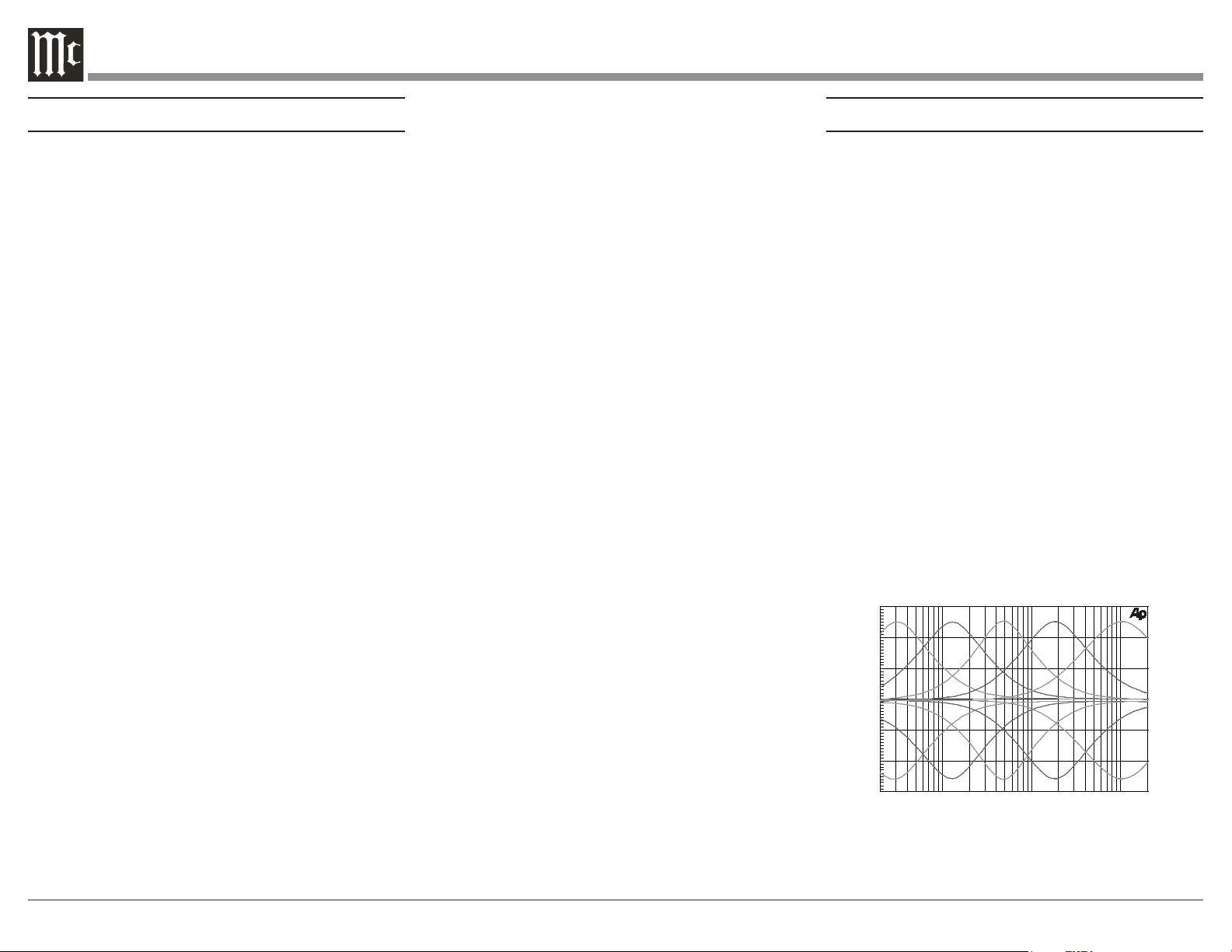
Equalizer Controls
Maximum Input Signal
High Level, 8V unbalanced, 16V balanced
Phono MM, 80mV
Phono MC, 8mV
Power Amplifier In, 16V
Preamplifier Output Impedance
220 ohms
Headphone Impedance
100 to 600 ohms
Voltage Gain
High Level to Rec Output: 0dB
High Level to Output 1 and 2: 15dB
Phono MM to Rec Output: 40dB
Phono MC to Rec Output: 60dB
Phono MM to Output 1 and 2: 55dB
Phono MC to Output 1 and 2: 75dB
Power Amplifier: 29dB
Power Control and Trigger Output
12VDC, 25mA
-15
20 50 100 200 500 1k
2k 5k 10k 20k
FREQUENCY IN HERTZ
0
- 5
A
M
P
L
I
T
U
D
E
I
N
D
E
C
I
B
E
L
S
-10
+ 5
+10
+15
Digital Audio Specications
Digital Input Signal Format
Coaxial and Optical Inputs - SPDIF (PCM)
MCT and USB Inputs - PCM, DSD
Digital Input Sample Rates
Optical: PCM - 16Bit, 24Bit - 44.1kHz to 192kHz
Coaxial: PCM -16Bit, 24Bit - 44.1kHz to 192kHz
MCT: PCM, SACD, -16Bit, 24Bit - 44.1kHz to 192kHz
USB: PCM - 16Bit, 24Bit, 32Bit - 44.1kHz to 384kHz
DXD - DXD352.8kHz, DXD384kHz
DSD - DSD64, DSD128, DSD256, DSD512
HDMI: PCM 24bit, 44.1kHz - 192kHz
DTS
Dolby Digital
Digital Inputs
Coaxial: 0.5V p-p/75 ohms
Optical: -15dbm to -21dbm (TOS Link)
MCT: 0.5V p-p/75 ohms
USB: USB Type B Connector
HDMI
Representative Equalizer
Boost/Cut Frequency Response
19
General Specications
Power Requirements
Field AC Voltage conversion of the MA8950 is not
possible. The MA8950 is factory configured for one
of the following AC Voltages:
100 Volts, 50/60Hz at 5.2 amps
110 Volts, 50/60Hz at 4.4 amps
120 Volts, 50/60Hz at 4.4 amps
220 Volts, 50/60Hz at 2.45 amps
230 Volts, 50/60Hz at 2.35 amps
240 Volts, 50/60Hz at 2.25 amps
Standby: Less than 0.25 watt
Note: Refer to the rear panel of the MA8950 for the cor-
rect voltage.
Overall Dimensions
Width is 17-1/2 inches (44.45cm)
Height is 7-5/8 inches (19.37cm) including feet
Depth is 18-3/4 inches (47.63cm) including the Front
Panel and Knobs
Weight
75 pounds (34.1 kg) net, 93 pounds (42.3 kg) in ship-
ping carton
Shipping Carton Dimensions
Width is 29-1/2 inches (74.93cm)
Depth is 29 inches (73.66cm)
Height is 17 inches (43.18cm)
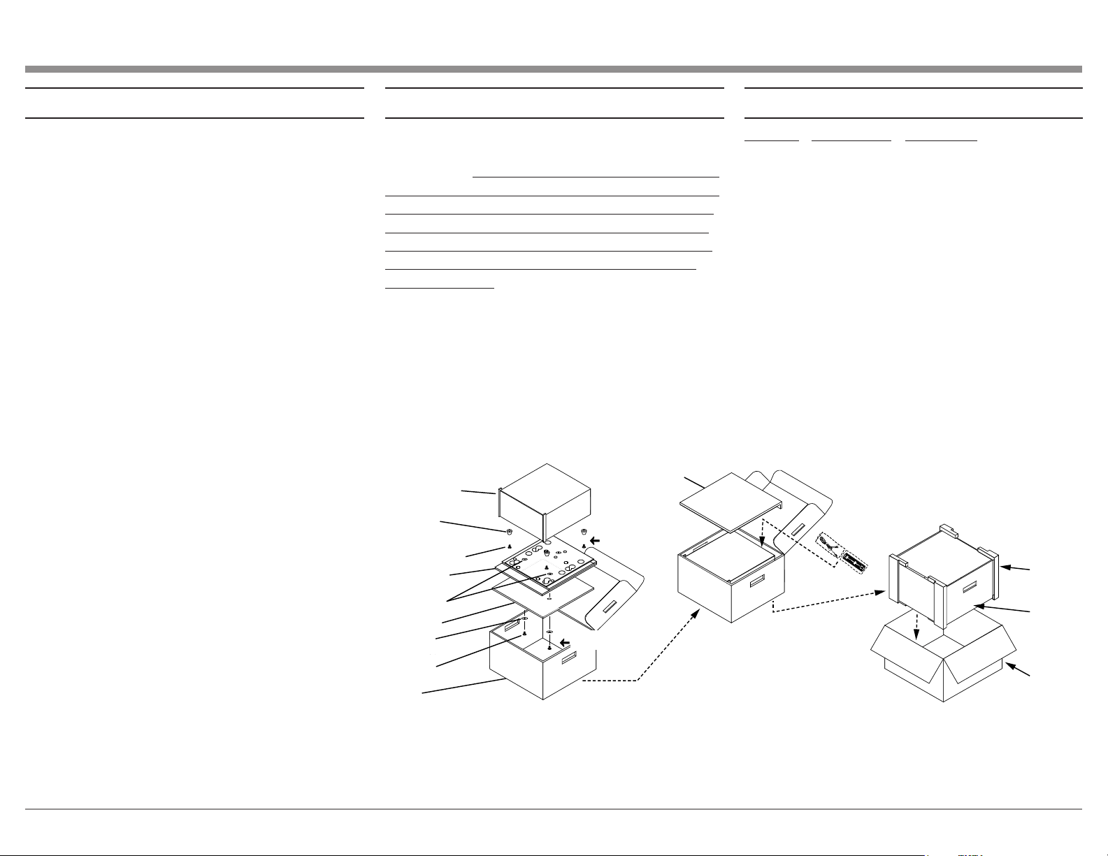
MA8950 Packing Material ListPacking Instructions
In the event it is necessary to repack the equipment for
shipment, the equipment must be packed exactly as
shown below. It is very important that the four plastic
feet are attached to the bottom of the equipment. Two
#10 x 2-1/2 inch screws and washers must be used to
fasten the unit securely to the bottom pad and wood
skid. This will ensure the proper equipment location
on the bottom pad. Failure to do this will result in
shipping damage.
Use the original shipping carton and interior parts
only if they are all in good serviceable condition. If
a shipping carton or any of the interior part(s) are
needed, please call or write Customer Service Depart-
ment of McIntosh Laboratory. Refer to page 2. Please
see the Part List for the correct part numbers.
Quantity Part Number Description
1 033888 Shipping carton
4 033887 End Cap
1 033697 Inner carton
1 033725 Top pad
1 034576 Bottom pad
1 034480 Wood skid
2 017218 Plastic foot (spacer)
2 401204 #10 x 2-1/2 inch
wood screw
2 404033 #10 flat washer 1-3/4 inch
4 017937 Plastic foot
4 400159 #10-32 x 3/4 machine screw
4 404080 #10 flat washer
BOTTOM PAD
PLASTIC FOOT
SPACER (4)
#10 X 2-1/2”
SCREW (2)
PLASTIC FOOT
SPACERS (2)
#10-32 X 3/4
MACHINE SCREW
WITH WASHER (4)
#10 X 1 3/4
FLAT WASHER
SHIPPING
CARTON
END C
AP (4)
INNER
CARTON
TOP PAD
INNER
CARTON
WOOD SKID
UNIT WITH
(4) FEET ON
BOTTOM COVER
IMPORTANT
(Read Above)
IMPORTANT
(Read Above)

The continuous improvement of its products is the
policy of McIntosh Laboratory Incorporated who
reserve the right to improve design without notice.
Printed in the U.S.A.
McIntosh Laboratory, Inc.
2 Chambers Street
Binghamton, NY 13903
www.mcintoshlabs.com
McIntosh Part No. 24115900