
McIntosh Laboratory, Inc. 2 Chambers Street Binghamton, New York 13903-2699 Phone: 607-723-3512 www.mcintoshlabs.com
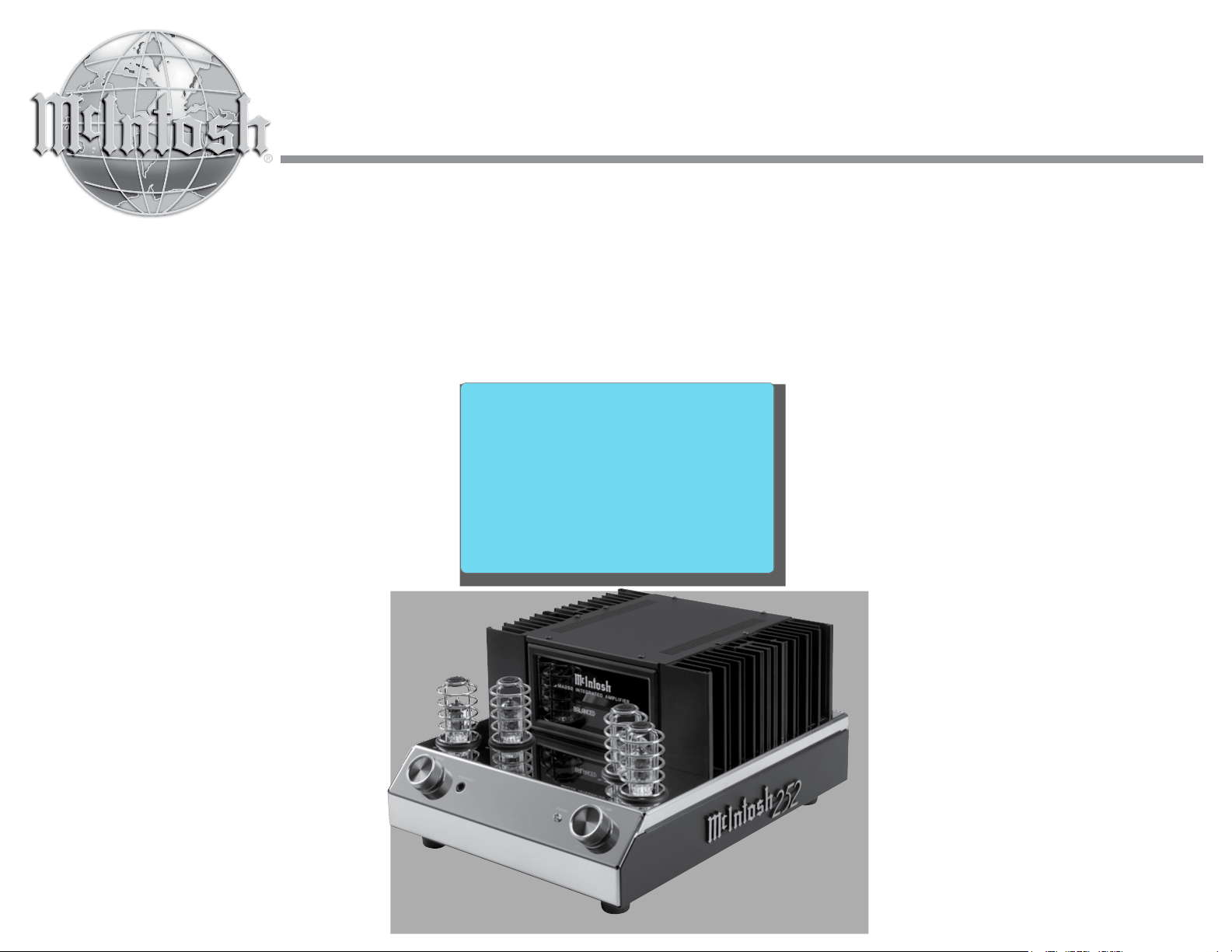
MA252
Integrated Amplifier
Owner’s Manual

2
Your decision to own this McIntosh MA252 Integrated
Amplifier ranks you at the very top among discrimi-
nating music listeners. You now have “The Best.” The
McIntosh dedication to “Quality,” is assurance that
you will receive many years of musical enjoyment
from this unit.
Please take a short time to read the information in
this manual. We want you to be as familiar as pos-
sible with all the features and functions of your new
McIntosh.
Copyright 2017 © by McIntosh Laboratory, Inc.
Table of Contents
Thank You
Please Take A Moment
Technical Assistance
If at any time you have questions about your McIntosh
product, contact your McIntosh Dealer who is familiar
with your McIntosh equipment and any other brands
that may be part of your system. If you or your Dealer
wish additional help concerning a suspected problem,
you can receive technical assistance for all McIntosh
products at:
McIntosh Laboratory, Inc.
2 Chambers Street
Binghamton, New York 13903
Phone: 607-723-3512
Fax: 607-724-0549
Customer Service
If it is determined that your McIntosh product is in
need of repair, you can return it to your Dealer. You
can also return it to the McIntosh Laboratory Service
Department. For assistance on factory repair return
procedure, contact the McIntosh Service Department
at:
McIntosh Laboratory, Inc.
2 Chambers Street
Binghamton, New York 13903
Phone: 607-723-3515
Fax: 607-723-1917
The serial number, purchase date and McIntosh Dealer
name are important to you for possible insurance
claim or future service. The spaces below have been
provided for you to record that information:
Serial Number: _______________________________
Purchase Date: _______________________________
Dealer Name: ________________________________
Important Safety Information is supplied in a separate document “Important Additional Operation Information Guide”
Safety Instructions .............................................................. 2
(Separate Sheet) ............................Important Additional
Operation Information Guide
Thank You and Please Take a Moment ...............................2
Technical Assistance and Customer Service .......................2
Table of Contents .................................................................2
Important Information ......................................................... 3
Unpacking the MA252 .....................................................4-5
General Information ............................................................6
Connector and Cable Information .......................................6
Introduction ......................................................................... 7
Performance Features ..........................................................7
Dimensions ..........................................................................8
Installation ...........................................................................9
Connections:
Rear Panel Connections ..................................................... 10
Connecting Components .............................................. 11-12
Connecting Loudspeakers ............................................ 13-14
Remote Control and Front Panel:
Remote Control Push-buttons ........................................... 16
How to use the Remote Control ......................................... 17
Front Panel Displays, Controls and Jack ........................... 18
Setup Mode:
How to Operate the Setup Mode ....................................... 19
Setup Functions:
Default Settings .........................................................19
Fir mware Version ......................................................19
Source Input On/Off and Renaming ....................19-21
Data Port ....................................................................21
Remote Control Codes ............................................... 21
IR Sensor ....................................................................22
Power Mode ...............................................................22
Factory Reset .............................................................22
Operation:
How to Operate the MA252 .........................................24-27
Trim Functions:
Balance .......................................................................24
Trim Level .................................................................. 25
Tone Control...............................................................25
Bass Control ...............................................................25
Treble Control ............................................................26
Information Display ...................................................26
Trim, Mute, Headphone Jack and Power Guard ........ 26
Protection Circuitry and Microprocessor Reset .........27
Photos ............................................................................28-29
Specifications.....................................................................30
Packing Instructions .......................................................... 31

3
IMPORTANT!
INSTRUCTIONS FOR REMOVAL
OF FOAM INSERT OVER THE
VACUUM TUBES PRIOR TO
CONNECTING THE A.C. POWER
SUPPLY CORD, START ON THE
NEXT PAGE.
4
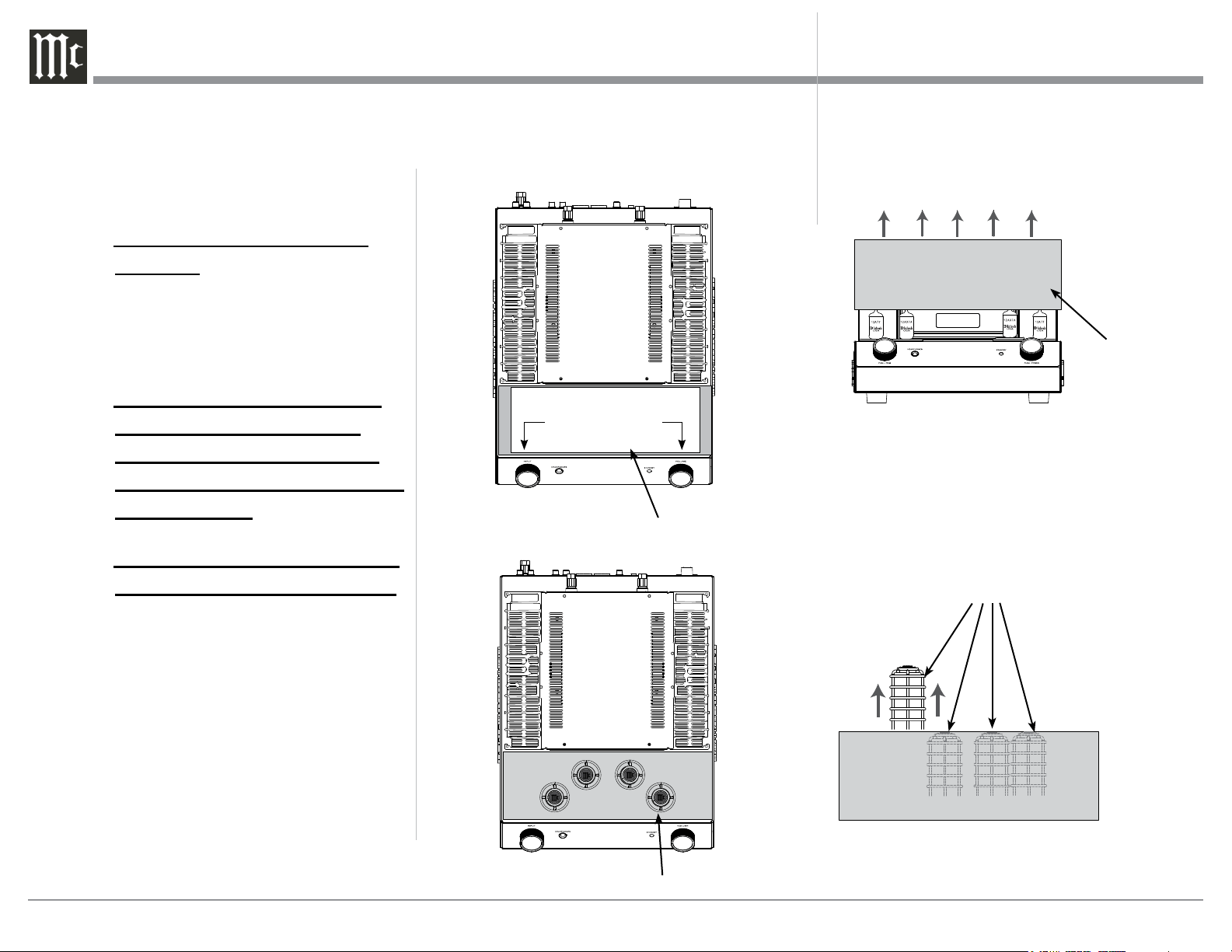
Figure C
Caution: To prevent damage to the MA252
Tubes during shipping, there is a
special foam insert surrounding the
Tubes of the Integrated Amplifier.
The Foam Insert must be
removed from the MA252
before connecting the AC
Power Supply Cord to the
integrated amplifier.
Failure to do so has the po-
tential of a Fire Hazard,
resulting in damage to the
MA252 and the surrounding
environment.
Follow these instructions for
removal of the packing foam
before connecting the AC
Power Supply Cord to the
MA252.
The MA252 has no user serviceable parts,
including the tubes. If repairs are needed they
must be performed by an authorized McIntosh
Service Agency. Follow the steps below to pre-
pare the MA252 for operation:
1. Orient the MA252 so the Front and Top of the
Integrated Amplifier is facing you. Refer to
figure A.
3. Carefully lift upright the Foam Insert Vacuum
Tube Cover and place it near to the MA252 Inte-
grated Amplifier. Refer to figure C.
TO AVOID A FIRE HAZARD, THE FOAM INSERT
OVER THE VACUUM TUBES MUST BE REMOVED
PRIOR TO CONNECTING THE A.C. MAINS POWER
SUPPLY CORD AND OPERATING THIS PRODUCT.
WARNING
REFER TO PAGE 3 IN THE MA252 OWNER’S
MANUAL FOR INSTRUCTIONS.
Figure A
Remove the Warning Sheet
Remove the
Foam Insert
Vacuum
Tube Cover
Figure B
2. Remove the Warning Sheet and save it with the
Shipping Carton for possible future use. Refer to
figures A and B.
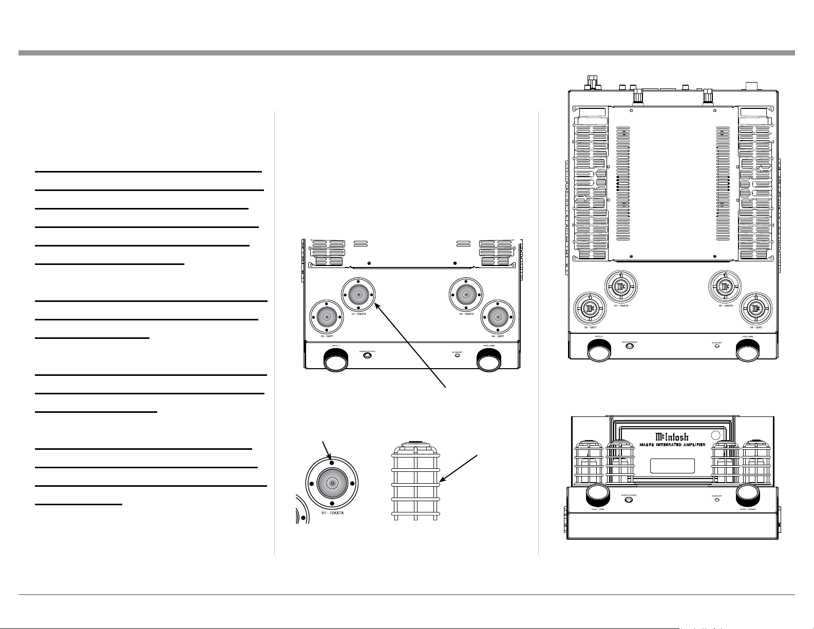
Vacuum Tube Shield Covers
4. Remove from the Foam, the four Vacuum Tube
Shield Covers and place them along the side of the
MA252 Integrated Amplifier. Save the Foam In-
sert Vacuum Tube Cover with the Shipping Carton
for possible future use. Refer to figure D.
Figure D
Remove the four Vacuum Tube Shield Covers
5
5. The MA252 Integrated Amplifier has four Small
Vacuum Tubes that are inserted into special
Vacuum Tube Sockets on the Stainless Steel Chas-
sis. Refer to figure E.
Each of the Tube Sockets have four pin openings
to accept the Vacuum Tube Shield Covers. Refer
to figure F.
Carefully install the Vacuum Tube Shield Covers
into each of the Vacuum Tube Sockets orienting
the Shield so the “Mc” on top of the Shield is fac-
ing forward. Refer to figures G and H.
Figure E
WA R N I NG:
The supplied Vacuum Tube Shield
Covers must be installed over each
of the four Small Vacuum Tubes
before the MA252 Integrated Am-
plifier is connected to AC Power
and activated for use!!
Failure to do so has the potential to
cause physical harm to human be-
ings and animals.
This could also result in damage to
the Vacuum Tubes and the MA252
Internal Circuitry.
It also prevents the potential of a
Fire Hazard, resulting in damage
to the MA252 and the surrounding
environment.
Special Vacuum Tube Sockets
Figure F
Vacuum Tube
Shield Covers
Pin Openings
BAL 15%
Figure G
Figure H
Unpacking the MA252
6
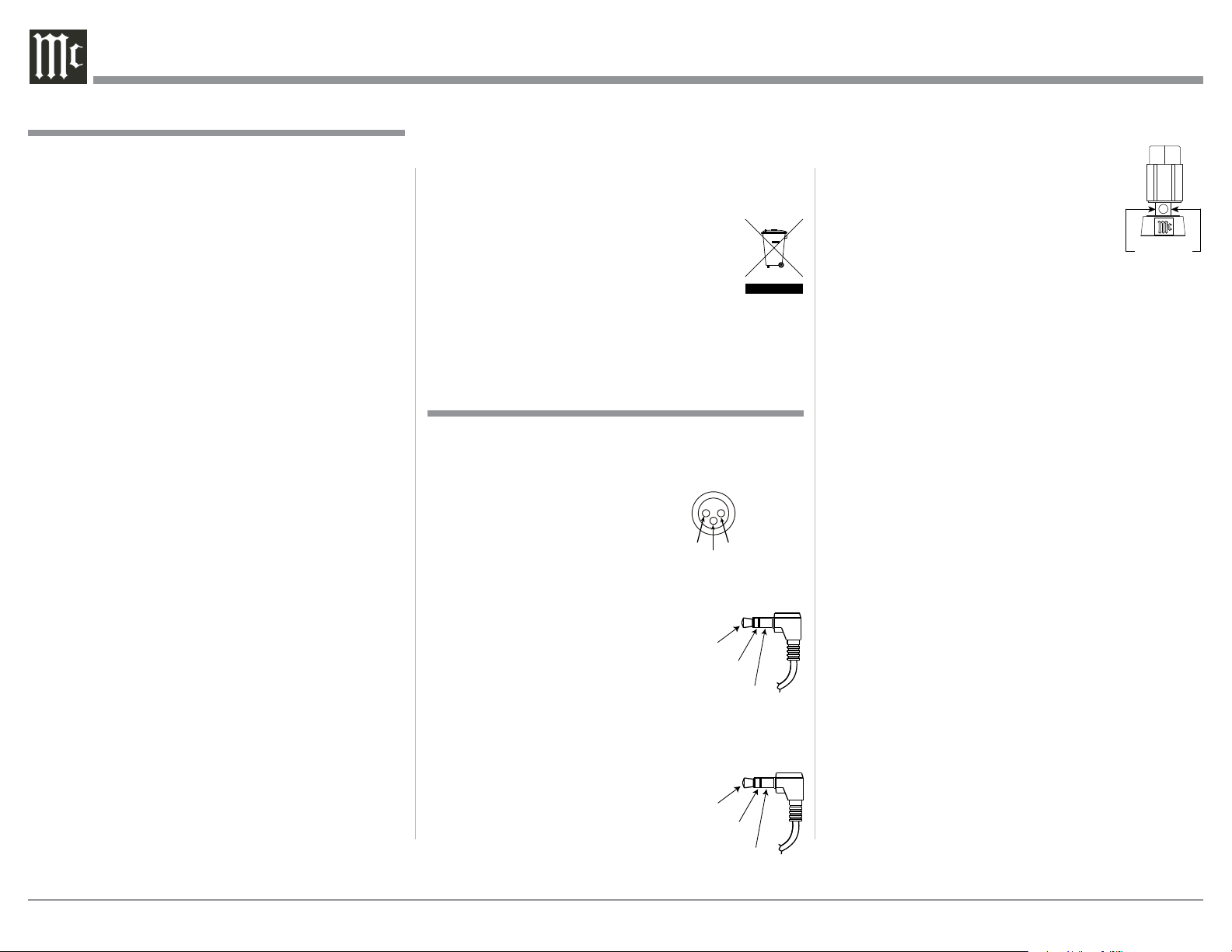
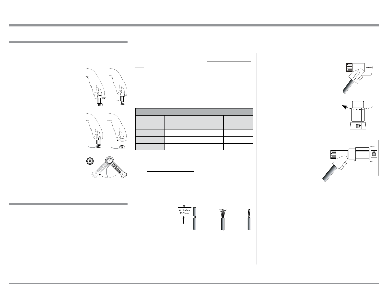
Output Terminal Connector
When cables with spade lugs are used
for Loudspeaker Connection, the spade
lugs need an opening of at least 3/10 inch
(7.6m m)
XLR Connectors
Below is the Pin configuration for the XLR Balanced
Input Connectors on the MA252. Refer to the diagram
for connection:
PIN 1: Shield/Ground
PIN 2: + Output
PIN 3: - Output
Power Control Connector
The Power Control Output Jack sends Power On/
Off Signals (+12 volt/0 volt) when
another McIntosh Component is
connected. A 3.5mm stereo mini
phone plug is used for connection to
the Power Control Output.
Data Port Connector
The Data Out Ports send Remote Control Signals to
Source Components. A 3.5mm stereo
mini phone plug is used for connec-
tion.
1. For additional connection information, refer to the
owner’s manual(s) for any component(s) connected
to the MA252.
2. Apply AC Power to the MA252 and other McIntosh
Component(s) only after all the system components
are connected together. Failure to do so may cause
a malfunction of system operations as the Micro-
processor’s Circuitry inside the components is
active when AC Power is applied.
3. The MA252 includes an Auto Off Power Save
Feature and the default setting is enabled. For
additional information including how to disable it,
refer to page 22.
4. When Power Amplifier Protection Circuitry of the
MA252 has activated, the Vacuum Tubes LEDs are
illuminated continuously with the color orange and
the sound will be muted.
5. When the Power Transformer has overheated due
to improper ventilation and/or high ambient operat-
ing temperature, AC Power is removed from the
MA252. Normal operation will resume when the
operating temperature is in a safe range again.
6. For the best performance and safety, it is important
to always match the impedance of the Loudspeaker
to the Power Amplifier connections. Refer to pages
10 and 11.
Note: The impedance of a Loudspeaker actually var-
ies as the Loudspeaker reproduces different
frequencies. As a result, the nominal impedance
rating of the Loudspeaker (usually measured at
a midrange frequency) might not always agree
with the impedance of the Loudspeaker at low
frequencies where the greatest amount of power
is required. Contact the Loudspeaker Manufac-
turer for additional information about the actual
impedance of the Loudspeaker before connecting
it to the McIntosh MA252.
7. The MA252 Remote Control is capable of operat-
ing other components. For additional information
go to www.mcintoshlabs.com.
8. When discarding the unit, comply with local rules
or regulations. Batteries should never be
thrown away or incinerated but disposed
of in accordance with the local regula-
tions concerning battery disposal.
9. For additional information on the MA252 and
other McIntosh Products please visit the McIntosh
Website at www.mcintoshlabs.com.
Connector and Cable Information
Data
Signal
N/C
Data
Ground
General Information
PIN 1
PIN 2
PIN 3
General Information, Connector and Cable Information
3/10 of an inch
(7.6millimeters)
Power
Control
Ground
N/C

7
Now you can take advantage of traditional McIntosh
standards of excellence in the MA252 Integrated Am-
plifier. The Power Amplifier Solid State section of the
MA252, with a power output of 100 watts per channel,
will drive a pair of quality Loudspeakers to a high
level of performance.
The flexible Tube Preamplifier section provides
connections for various analog input sources.
The MA252 reproduction is sonically transparent
and absolutely accurate. The McIntosh Sound is “The
Sound of the Music Itself.”
Introduction
Performance Features
• Power Output
The MA252 consists of 100 watts (8 ohm) or 160 watts
(4 ohm) per channel Stereo Power Amplifier with
less than 0.03% distortion. The McIntosh MA252 is
designed for connection of a single 8 ohm or 4 ohm
Loudspeaker per channel. The Power Amplifier uses
ThermalTrak
1
Output Transistors for lower distortion
and cool operation.
• Power Guard
The patented McIntosh Power Guard circuit prevents
amplifier clipping and protects your valuable Loud-
speakers.
• Sentry Monitor and Thermal Protection
McIntosh Sentry Monitor power output stage protec-
tion circuits ensure the MA252 will have a long and
trouble free operating life. Built-in Thermal Protection
Circuits guard against overheating.
1
ThermalTrak™ and ON Semiconductor are trademarks of Semi-
conductor Components Industries, LLC
• Electronic Output Switching
The Preamplifier uses Logic Controlled Electromag-
netic Switches on all low level outputs and operating
functions for reliable, noiseless, distortion free switch-
ing.
• Moving Magnet Phono Inputs
The MA252 Moving Magnet Input Circuitry uses
the latest design to provide the lowest possible noise,
distortion and flat frequency response.
• Tone Controls
The Bass and Treble Trim Controls provide up to
10dB of boost or cut. The MA252 remembers the Bass
and Treble Setting for each input.
• Multifunction Display
The Front Panel Display indicates source selection,
volume levels and setup functions.
• Power Control Output
A Power Control connection for convenient Turn-On
of a McIntosh Component.
• Remote Control
The Data Port together with the supplied Remote Con-
trol provide control of McIntosh Source Components
connected to the MA252.
• Special Power Supply
The large Power Transformer, multiple filter capaci-
tors with 60 Joules of Energy Storage and regulated
Power Supply ensure stable noise free operation even
though the power line varies.
• McIntosh Custom Binding Posts
McIntosh Patented gold plated output terminals deliver
high current output. They accept large diameter wire
and spade lugs. Banana plugs may also be used only in
the United States and Canada.
• Super Mirror Finish Chassis with Glass Panel
The famous McIntosh Stainless Steel Chassis with
Super Mirror Finish ensures the pristine beauty of the
MA252 will be retained for many years. The famous
McIntosh Illuminated Glass Panel uses long life Light
Emitting Diodes (LEDs).
Introduction and Performance Features
8
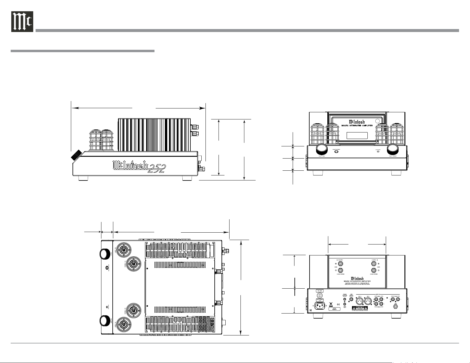
Dimensions
Dimensions
The following dimensions can assist in determining
the best location for your MA252. There is additional
information on the next page pertaining to installing
the MA252 into cabinets.
7-5/8"
19.4cm
Front View of the MA252
Top View of the MA252
Left Side View of the MA252
Right Side View of the MA252
16-1/2"
41.9cm
7-1/32"
17.9cm
14-3/4"
37.5cm
12"
30.5cm
1-1/2"
3.8cm
BAL 15%
3"
7.62cm
4-1/16"
10.3cm
6-13/16"
17.3cm
1-1/2"
3.8cm
1-1/2"
3.8cm
9
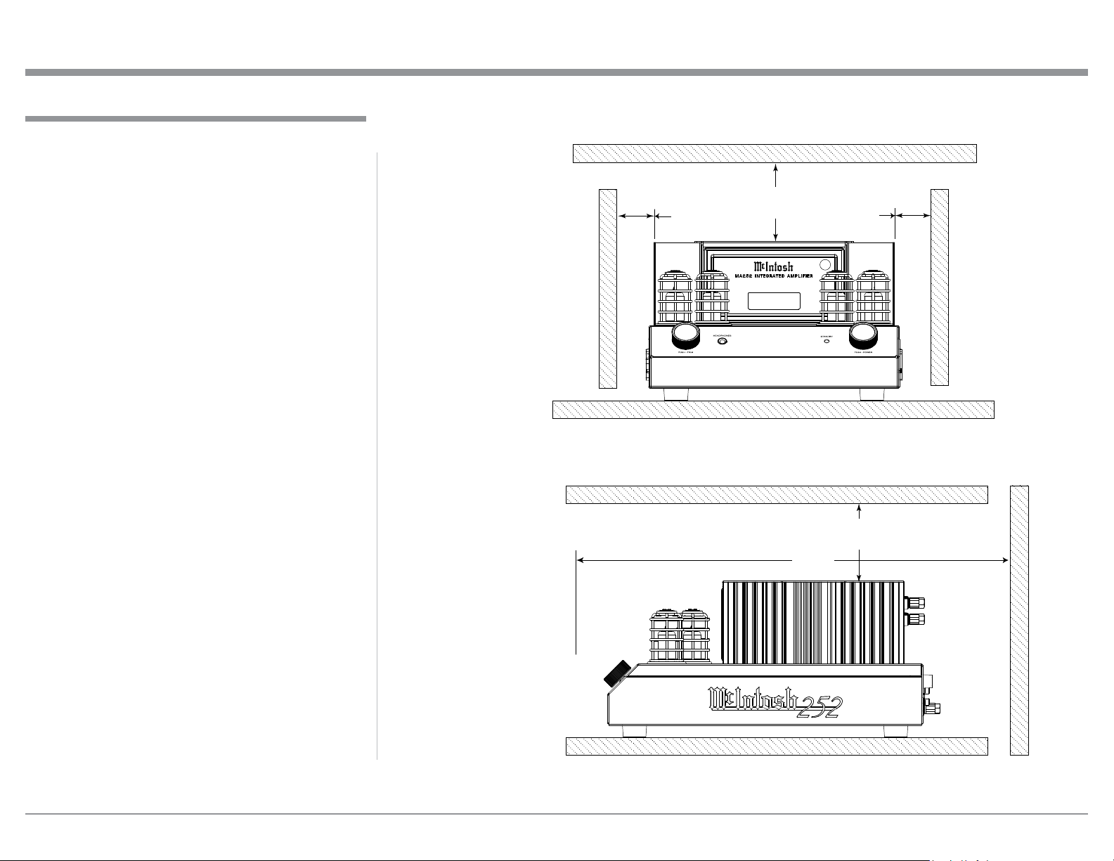
Installation
Installation
MA252 Side View
18"
45.7cm
MA252 Front View
6"
15.3cm
6"
15.3cm
2"
5.1cm
2"
5.1cm
BAL 15%
The MA252 Integrated Amplifier is designed to be
placed upright on a table or shelf, standing on its feet.
The required ventilation requirements are shown.
Always provide adequate ventilation for your MA252.
Cool operation ensures the longest possible operating
life for any electronic instrument. Do not install the
MA252 directly above a heat generating device, such
as a Power Amplifier. Allow at least 6 inches (15.3cm)
above the top, 5/8 inch (1.6cm) below the bottom and
2 inches (5.1cm) on each side of the Amplifier, so that
airflow is not obstructed. Allow 18 inches (45.7cm) of
depth for airflow and cable connections.
10
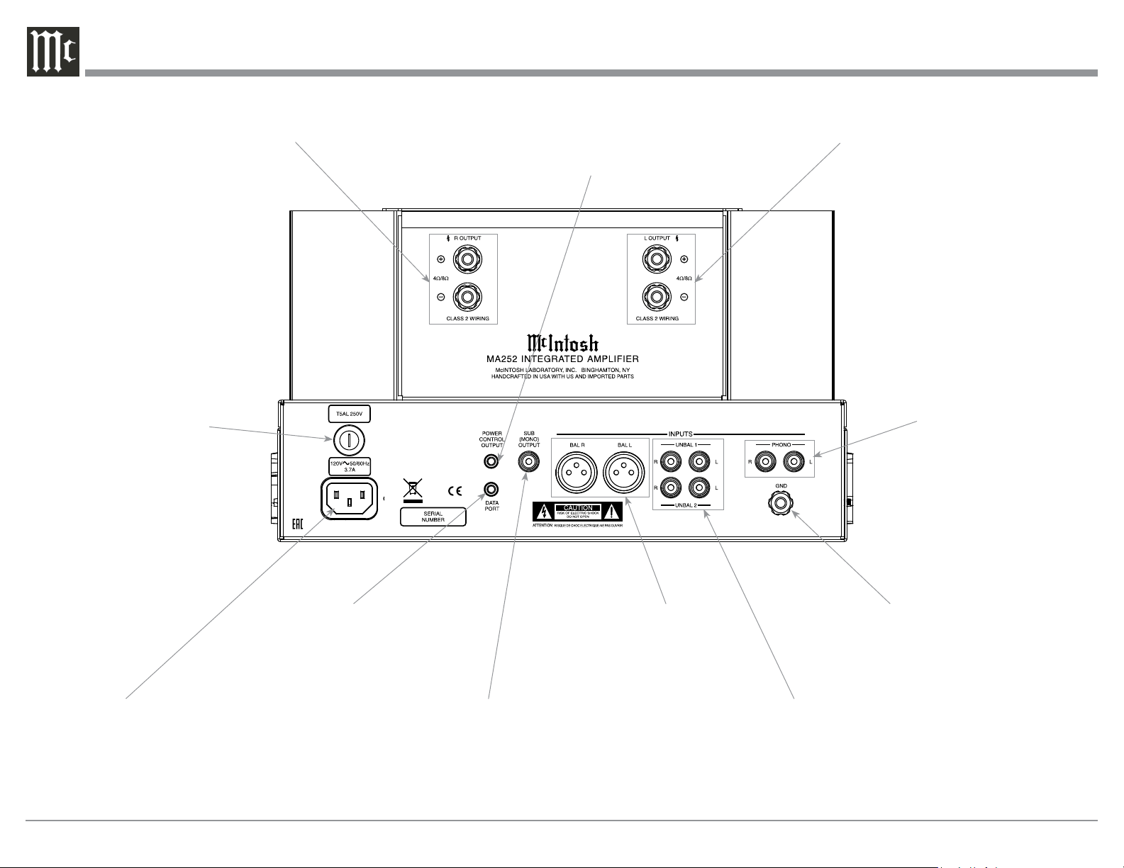
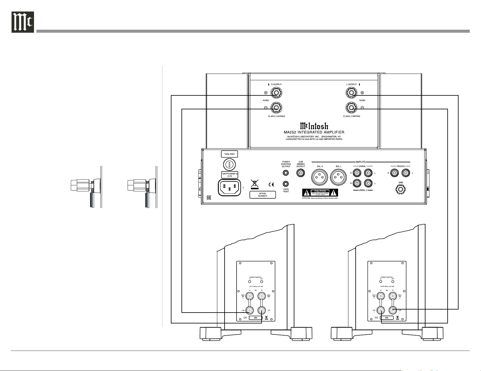
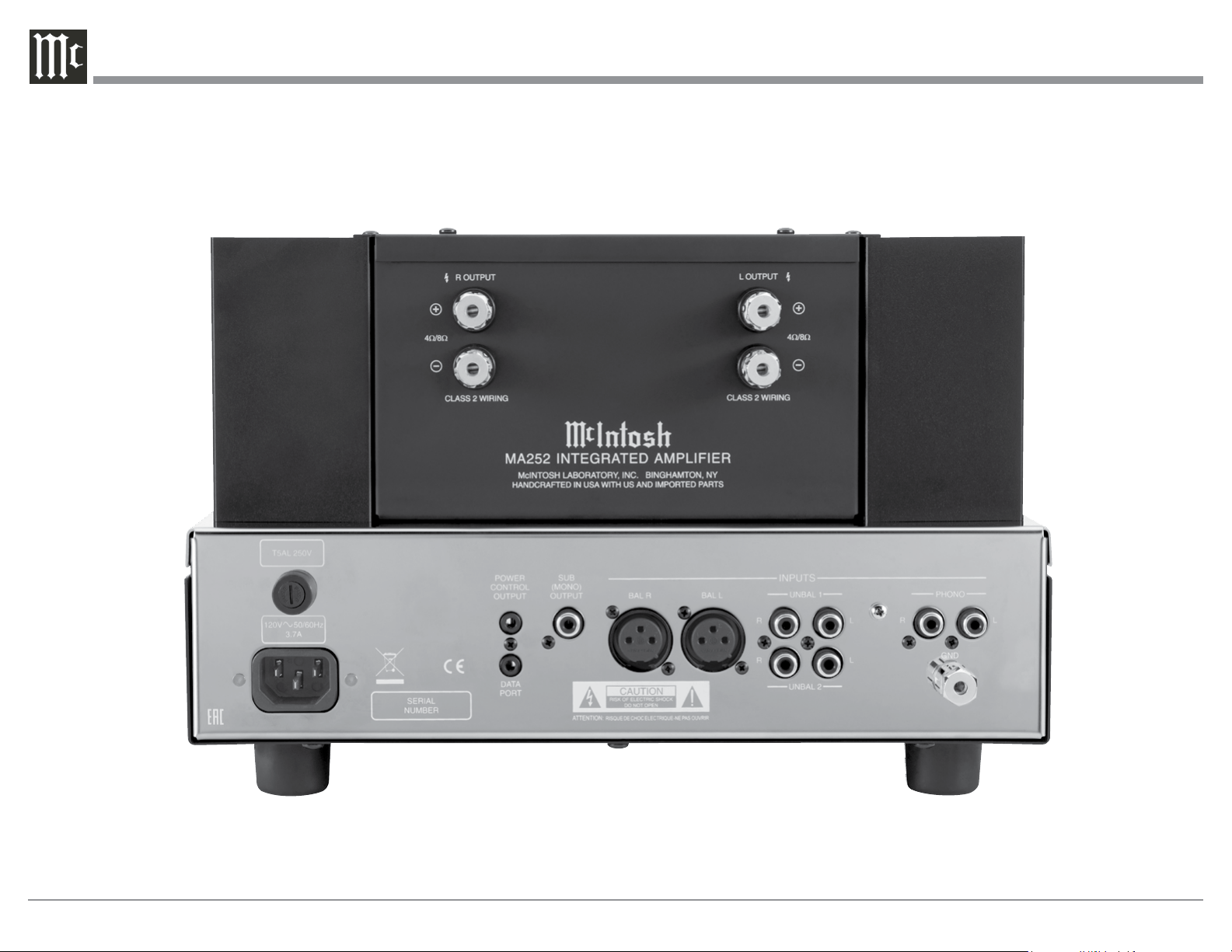
MA252 Rear Panel Connections
Right OUTPUT
connections for a 4 or
8 ohm Loudspeaker
PHONO accepts signals
from a Moving Magnet
Phono Cartridge or a
high output Moving Coil
Cartridge
GND terminal
accepts a ground
wire from a
turntable
BALANCED INPUTS
accept high level pro-
gram source signals
POWER CONTROL OUTPUT sends turn
On/Off signals to a McIntosh Component
when the MA252 is switched On/Off
DATA PORT sends signals
to a Source Component
to allow control with the
MA252 Remote Control
Connect the MA252 power cord to a
live AC outlet. Refer to information
on the back panel of your MA252 to
determine the correct voltage for your
unit
Main Fuse holder, refer to
information on the back
panel of your MA252 to
determine the correct fuse
size and rating
Left OUTPUT
connections for a 4 or
8 ohm Loudspeaker
UNBALanced INPUTS
1 and 2 accept high level
program source signals
SUB (MONO) OUTPUT
full frequency range Audio
Output for connection to
an actively powered Sub-
Woofer

11
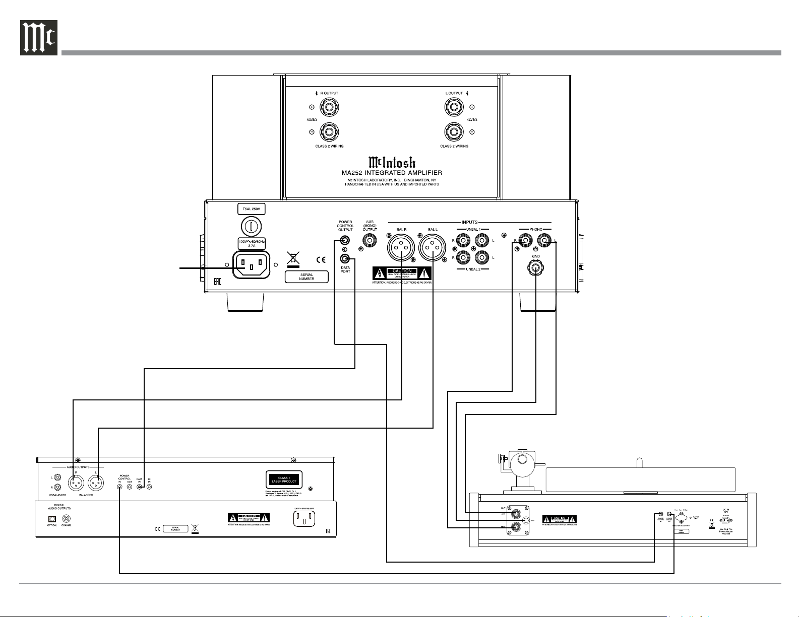
Connecting Components
The MA252 has the ability to automatically switch
power On/Off to McIntosh Source Components via
the Power Control connections. The Data Port Con-
nections allow for the remote operation of basic func-
tions using the MA252 Remote Control.
The connection instructions below, together with
the MA252 Input and Output Connection Diagram on
the next page is an example of a typical audio system.
Your system may vary from this, however the actual
components would be connected in a similar manner.
For additional information refer to “Connector and
Cable Information” on page 6.
Power Control Connections:
1. Connect a Control Cable from the MA252
POWER CONTROL OUTPUT Jack to the Power
Control In on the Turntable.
2. Connect a Control Cable from the McIntosh Turn-
table Power Control Out Jack to the CD Player
Power Control In Jack.
3. Connect any additional McIntosh Components in
a similar manner, as outlined in steps 1 thru 2.
Data Control Connections:
4. Connect a Control Cable from the MA252 DATA
PORT Jack to the CD Player Data In Jack.
5. Connect another McIntosh Component in a similar
manner instead of the CD Player Data In Jack, as
outlined in step 7.
Audio Connections:
6. Connect Balanced Cables from the MA252 BAL-
anced INPUT Connectors to the CD Player Audio
Output.
7. Connect the Audio Cables coming from the
Turntable to the MA252 PHONO Input Jacks (for
a Moving Magnet Cartridge or a Moving Coil
Cartridge with High Audio Output Level).
8. Connect any additional Components in a similar
manner, as outlined in steps 6 and 7.
Ground Connections:
9. Connect the Ground Cable coming from the Turn-
table to the MA252 GND Binding Post.
12
Connecting Components
CD Player
Tur ntable
Connect to
AC Outlet
13
Caution: Do not connect the AC Power Cord to the
MA252 Rear Panel until after the Loudspeaker
Connections are made. Failure to observe this
could result in Electric Shock.
The connection instructions below, together with the
MA252 Connection Diagram located on the next page
is an example of a typical audio system. Your system
may vary from this, however the actual components
would be connected in a similar manner. For addition-
al information refer to “Connector and Cable Informa-
tion” on page 6.
The McIntosh MA252 Power Amplifier Circuitry
is designed for a Loudspeakers with an impedance
of 8 Ohms or 4 Ohms. Connect a single Loudspeaker
only to the Right and Left Output Terminals.
When connecting Loudspeakers to the MA252 it
is very important to use cables of adequate size, so
there is little to no power loss in the cables. The size is
specified in Gauge Numbers or AWG (American Wire
Gauge). The smaller the Gauge number, the larger the
wire size:
Loudspeaker Cable Distance vs Wire Gauge Guide
Loudspeaker
Impedance
25 feet
(7.62 meters)
or less
50 feet
(15.24 meters)
or less
100 feet
(30.48 meters)
or less
2 Ohms
12AWG 10AWG 8AWG
4 Ohms
14AWG 12AWG 10AWG
8 Ohms
16AWG 14AWG 12AWG
1. Prepare the Loudspeaker Hookup Cable for attach-
ment to the MA252 Power Amplifier:
Bare wire cable ends:
Carefully remove sufficient insulation from the
cable ends, refer to figures F, G & H. If the cable
is stranded, carefully twist the strands together
as tightly as possible.
Notes: 1. If desired, the twisted ends can be tinned
with solder to keep the strands together.
2. The prepared bare wire cable ends may be
inserted into spade lug connectors.
3. Banana plugs are for use in the United
States and Canada only.
Banana Plugs are for use in the United States and
Canada only:
2. Attach the previously prepared bare wire cable ends
into the banana plugs and secure
the connections. Refer to figure I.
3. Rotate the Output Terminal Post
clockwise until it is nger tight.
Refer to gure J. Then using the
McIntosh Wrench, rotate the top of
the Output Terminal one quarter of
a turn (90°). Do not over tighten.
Refer to gure E.
4. Referring to figure K, connect the
Loudspeaker hookup cables with
banana plugs into the hole at the
top of the terminal to the
MA252 Negative Output
Terminal and Positive
Output Terminal to the
Loudspeaker Terminal
Connections being care-
ful to observe the correct
polarities.
Note: The illustration located on the separate folded sheet
“Mc2B” is for connection to an 8Ω (ohms) Loudspeak-
er.
If the Loudspeaker’s impedance is in-between
the available connections, use the nearest lower
impedance connection. Refer to “General Informa-
tion” Note 6 on page 6 for additional information.
WARNING: Loudspeaker terminals are hazard-
ous live and present a risk of electric
shock. For additional instruction on
making Loudspeaker Connections con-
tact your McIntosh Dealer or McIn-
tosh Technical Support.
Output Terminals
When connecting the Loudspeaker Hookup Cables to
the MA252 Power Amplifier Output Terminals please
follow the steps below:
1. Rotate the top of the Output Terminal Post coun-
terclockwise until an opening
appears. Refer to gures A and
B.
2. Insert the Loudspeaker hookup
cable into the Output Terminal
Post opening or the cable spade
lug around the center post of
the Output Terminal. Refer to
gure C.
3. Rotate the top of the Output
Terminal Post clockwise until it
is nger tight. Refer to gure D.
4. Place the supplied McIntosh
Wrench over the top of the Out-
put Terminal and rotate it one
quarter of a turn (90°) to secure
the Loudspeaker Cable Connec-
tion. Do not over tighten. Refer
to gure E.
Figure A
Opening
Figure B
Figure C Figure D
Figure E
How to Connect Loudspeakers
Figure F
Figure G
Figure H
Figure I
Figure J
Figure K
14
5. Connect the MA252 power cord to an active AC
outlet.
Spade Lug or Wire Connections:
6. Connect the Loudspeaker hookup cables to the
MA252 Negative Output Terminal and Positive
Output Terminal to the Loudspeaker Terminal
Connections being careful to observe the cor-
rect polarities. Insert the spade lug connector or
prepared section of the cable end into the terminal
side access hole, and tighten the terminal cap until
the cable is firmly clamped into the terminals so
the lugs or wire cannot slip out. Refer to figures L
and M.
Note: The illustration located on the separate folded
sheet “Mc2B” is for connection to an 8Ω
(ohms) Loudspeaker.
Refer to “General Information” Note 6 on page 6
for additional information.
WARNING: Loudspeaker terminals are hazard-
ous live and present a risk of electric
shock. For additional instruction on
making Loudspeaker Connections con-
tact your McIntosh Dealer or McIn-
tosh Technical Support.
7. Connect the MA252 power cord to an active AC
outlet.
Connecting Loudspeakers
Right Loudspeaker
+
-
Left Loudspeaker
+
-
Figure L
Figure M

15
16
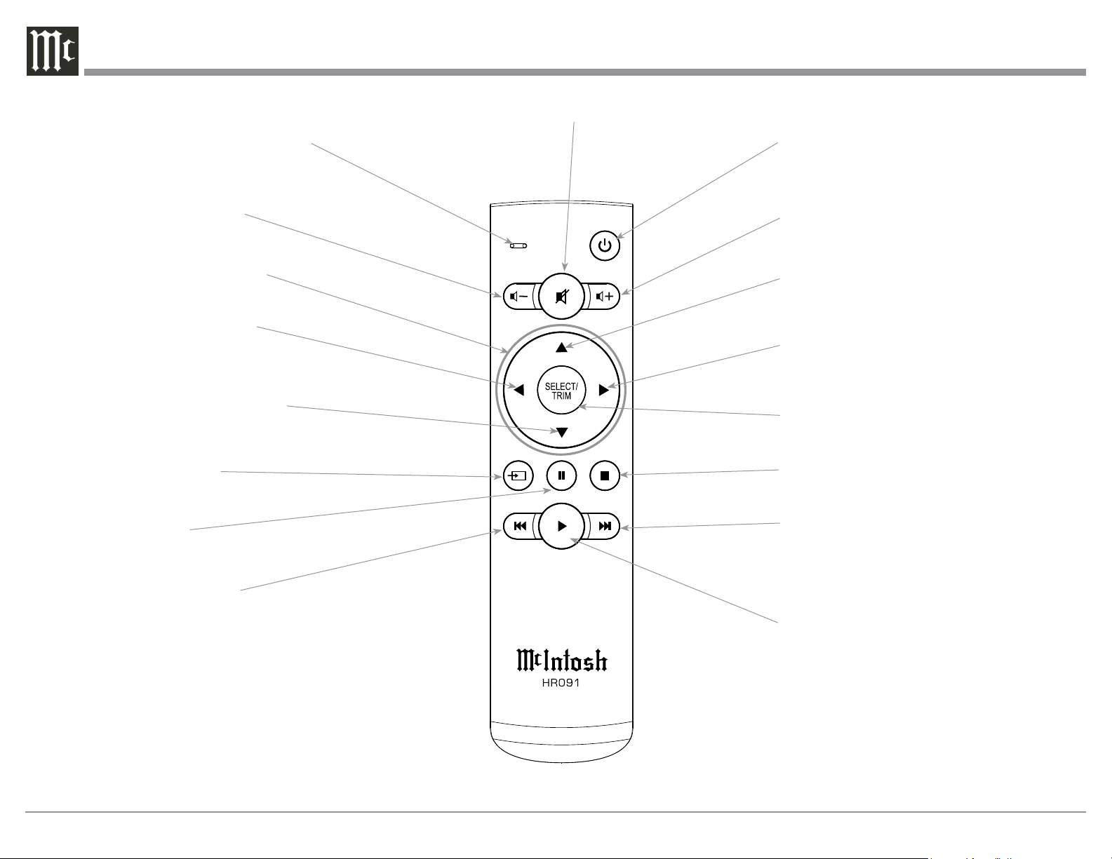
Note: Push-buttons whose function is not identified above are for use with other McIntosh Products.
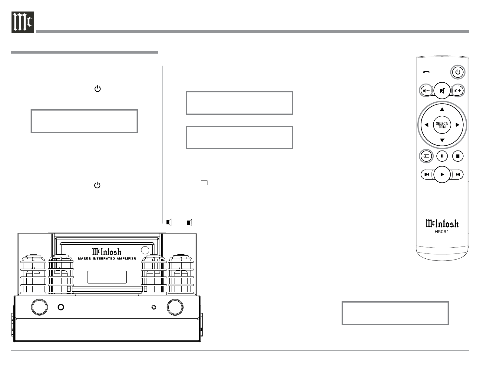
HR091 Remote Control Push-Buttons
Activates TRIM Mode
Selects the desired INPUT
Select the desired active TRIM function; also
manually tune up the dial with contemporary Mc-
Intosh Tuners
Adjusts the active TRIM Function
Adjusts the active TRIM Function
Directional Push-buttons - Up, Down,
Left and Right
LED illuminates during the time a
remote command is sent to the MA252
Increases the volume levelDecreases the volume level
Mutes and unmutes the audio
Powers the MA252 ON or OFF
Select the desired active TRIM function;
also manually tune down the dial with con-
temporary McIntosh Tuners
Selects Previous Track during
CD Playback
Selects Next Track during CD Playback
Stop CD Playback
Pause CD Playback
Starts CD Playback

17
How to use the Remote Control
How to use the Remote Control
The supplied Remote Control performs the various
Operating Functions for the MA252 Integrated Am-
plifier.
Note: Refer to the “How to Operate” Section of this
manual for additional information.
Input Source Selection
Press the Push-button → to select the desired pro-
gram source.
Volume
Press the + or - Push-buttons to increase or de-
crease the listening level.
Mute
Press the (Mute) Push-button to mute the audio and
a second time to resume listening.
Select Push-Button
Press the SELECT/TRIM Push-button to activate the
Trim Mode. Then use the Directional Push-Buttons to
select a Trim Mode Function and make changes.
Directional Push-Buttons
After having pressed the SELECT Push-button,
press the ▲ ▼ (Up or Down) Push-buttons to scroll
through the various Trim Functions. Then press the ◄
► (Left or Right) Push-buttons to make a change to
the current Trim Setting.
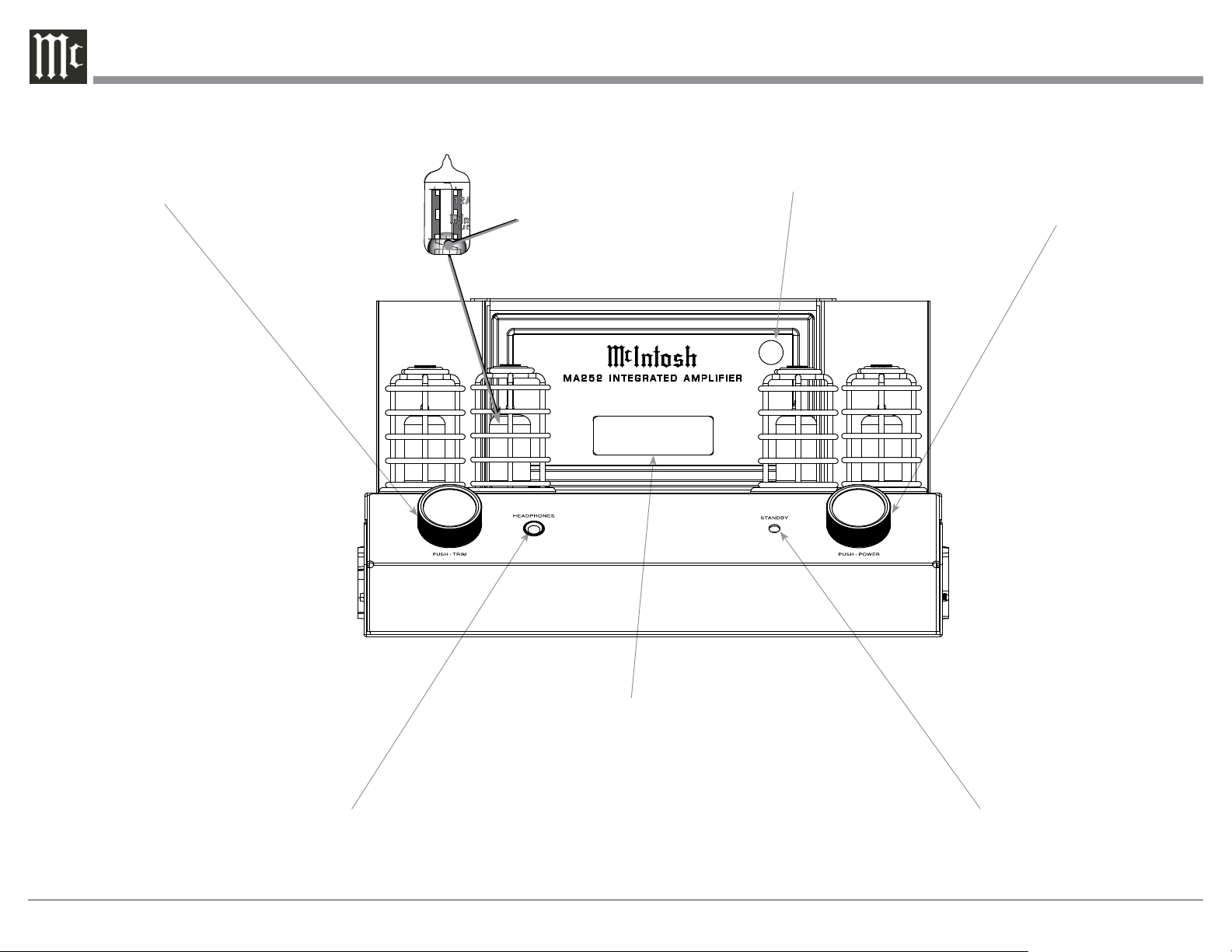
18
IR Sensor receives
commands from a
Remote Control
STANDBY/ON LED Indicator
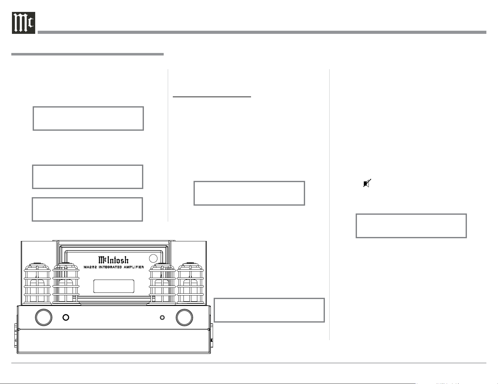
INFORMATION DISPLAY indicates
the Sources, Volume, Trim Operational
Functions and Setup Mode Settings
VOLUME Control allows adjustment
of the listening level for both chan-
nels. Switches the MA252 ON or OFF
(Standby). Also used to change the
various TRIM and SETUP Functions
and Resets the microprocessors
Connection for low impedance
dynamic headphones, for private
listening
INPUT Control used to select a
source for listening and recording.
The control is also used to enter the
TRIM or SETUP Modes and select
the various functions
Front Panel Displays, Controls and Jack
BAL 15%
LED Illumination Color:
Orange - Warmup Mode and
Power Guard Activates
Green - Normal Operation
Preamplifier Small Signal
Vacuu m Tube
19
3. Rotate the INPUT Control to select the Setup
Mode Menu item, “SETUP: Inputs, (Hold IN-
PUT)”. Refer to figure 3.
Continue to rotate the INPUT CONTROL to view
the other SETUP Mode Options.
4. To exit from the SETUP Mode, press and hold in
the INPUT Control and the Front Panel Display
will indicate its normal display. Refer to figure 1.
Your McIntosh MA252 has been factory configured
to allow immediate enjoyment of superb audio with-
out the need for further adjustments. If you wish to
make changes to the factory default settings, a Setup
Feature is provided to customize the operating settings
using the Front Panel Information Display. Refer to the
MA252 Front Panel Illustration on the previous page
while performing the following steps.
Note: If the MA252 is currently On,
proceed to step 2.
1. Press the STANDBY/ON Push-button on the Front
Panel or press the (Power ON) Push-button on
the Remote Control to switch On the MA252. The
MA252 will go through a brief startup initializa-
tion with the Front Panel Information Display first
indicating “MA252”, followed by the last used
source and volume setting. This is followed by the
volume setting indication starting at zero and then
increasing to the last used volume setting. Refer to
figure 1.
2. Press and hold in the INPUT Control until
the Front Panel Information Display indicates
“MA252 V1.00, (or higher Firmware version)
- S/N: AGA____” (Serial Number). Refer to
figure 2.
The MA252 functionality is controlled by internal
software that is know as Firmware. The Firmware for
the MA252 and can be identified at any time by utiliz-
ing the Setup Mode.
1. Press and hold in the INPUT Control to enter
Setup Mode.
2. Referring to the Front Panel Information Display-
the number after the character “V” is the Firm-
ware number. Refer to figure 2.
How to Operate the Setup Mode
The Default Settings Chart below indicates the Func-
tion Name, Default Setting and the Page Number for
additional information.
Default Settings
Firmware Version
Default Settings
Function Name Setting Page No.
MA252 V_._ _ 19
INPUTS On / Rename 19-21
DATA PORT All Data 21
IR Codes Normal 21
IR Sensor Enabled 21
Power Mode Enabled 21
Setup
Figure 2
MA252 V1.00
S/N: AGA____
Figure 1
UNBAL 1 15%
The MA252 provides the ability to switch unused
INPUTS Off (or back On if they have been previously
switched Off). The default INPUT Names can be
changed to match the name of the component con-
nected to it or any other custom name desired (within
10 Characters).
INPUT SWITCHED ON/OFF:
In the following example, the UNBAL 2 Input will be
switched Off.
Note: When an INPUT is swiched Off, its name will
no longer appear on the Front Panel Informa-
tion Display when using the INPUT Control
(Front Panel or Remote Control).
1. Press and hold in the INPUT Control to enter the
SETUP MODE. Refer to figure 2.
Input Settings
Figure 3
SETUP: Inputs
(Hold INPUT)
20
play. The character “B” is flashing to indicate it is
ready to be changed. Refer to figure 9.
15. Rotate the VOLUME (ADJUST) Control to change
the character “B” to “C”. Refer to figure 10.
16. Rotate the INPUT Control until the character “A”
is flashing, then rotate the VOLUME (ADJUST)
Control to change the character “A” to “D”. Refer
to figure 11.
17. Rotate the INPUT Control until the character “L”
is flashing, then rotate the VOLUME (ADJUST)
Control until the “_” empty space to the right of
character D is flashing. Refer to figure 12.
18. Rotate the INPUT Control until the “_” empty
space to the right of the just entered empty space
is flashing, then rotate the VOLUME (ADJUST)
Control to change the “_” empty space to character
to “P”. Refer to figure 13.
UME Control until the display indicates “SETUP:
UNBAL 2, On / Name”.
10. Exit the SETUP Mode by several presses of the
INPUT Control.
R ENAM E IN PUT:
In the following example, the BAL (BALANCED) In-
put will be renamed to match up with the component
connected (refer to page 8, step 6).
The MA252 Default Input Names (UNBAL 1, BAL,
PHONO, etc.) as indicated on the Front Panel Dis-
play can be customized to a different name up to ten
characters long (TUNER, CD PLAYER, etc.). The
available characters for renaming the input include the
following: ! < > * , / - _ 0 1 2 3 4 5 6 7 8 9 A B C D E
F G H I J K L M N O P Q R S T U V W X Y Z .
In the following example, the BAL Input will be re-
named to “MEDIA SVR”.
11. Press and hold in the INPUT Control to enter the
SETUP MODE. Refer to figure 2, on page 19.
12. Rotate the INPUT Control until “SETUP: Inputs,
(Hold INPUT)” appears on the Information Dis-
play. Refer to figure 7.
13. Press and hold in the INPUT Control until “SET-
UP: UNBAL 1, On/Name(Hold IN)” appears on
the Display. Rotate the INPUT Control to select
the BAL Input. Refer to figure 8.
14. Press and hold in the INPUT Control until “RE-
NAME: BAL, >BAL < ” appears on the Dis-
2. Rotate the INPUT Control until “SETUP: Inputs,
(Hold INPUT)” appears on the Information Dis-
play. Refer to figure 3 on page 19.
3. Press and hold in the INPUT Control until “SET-
UP: UNBAL 2, On / Name (Hold IN)” appears on
the Display. If necessary rotate the INPUT Control
to select the UNBAL 2 Input. Refer to figure 5.
4. To switch the UNBAL 2 Input Off, rotate the
VOLUME Control until the display indicates
“SETUP: UNBAL 2, Off”. Refer to figure 6.
5. Exit the SETUP Mode by several presses of the
INPUT Control.
In the following example, the UNBAL 2 Input will be
switched On.
Notes: 1. When an INPUT is swiched ON, its name will
appear on the Front Panel Information Display
when using the INPUT Control (Front Panel or
Remote Control).
6. Press and hold in the INPUT Control to enter the
SETUP MODE. Refer to figure 2, on page 19.
7. Rotate the INPUT Control until “SETUP: Inputs,
(Hold INPUT)” appears on the Information Dis-
play. Refer to figure 3, on page 19.
8. Press and hold in the INPUT Control until “SET-
UP: UNBAL 2, Off” appears on the Display. If
necessary rotate the INPUT Control to select the
UNBAL 2 Input. Refer to figure 6.
9. To switch the UNBAL 2 Input On, rotate the VOL-
Input Settings, con’t
Figure 6
SETUP: UNBAL 2
Off
Figure 8
SETUP: BAL
On/Name(Hold IN)
Figure 10
RENAME: BAL
>CAL
Figure 12
RENAME: BAL
>CD
Figure 11
RENAME: BAL
>CDL
Figure 7
SETUP: Inputs
(Hold INPUT)
Figure 9
RENAME: BAL
>BAL
Figure 13
RENAME: BAL
>CD P
Figure 5
SETUP: UNBAL 2
On/Name(Hold IN)
21
Data Port Connection between the MA252 and a
McIntosh Source Component allow for basic function
control of the source component using the MA252
Remote Control. By default, the Data Port setting of
“All Data” sends the received IR Data to the DATA
PORT Output Jack. To dedicate the Data Port for only
one MA252 source component perform the following
Steps:
1. Press and hold in the INPUT Control to enter the
SETUP MODE. Refer to figure 2 on page 19.
2. Rotate the INPUT Control until “SETUP: Data
Ports, All DATA” appears on the Information Dis-
play. Refer to figure 20.
3. Rotate the VOLUME (ADJUST) Control to select
the desired MA252 Input. Refer to figure 21.
4. Exit the SETUP Mode by several presses of the
INPUT Control.
19. Rotate the INPUT Control until the “_” empty
space to the right of character P is flashing, then
rotate the VOLUME (ADJUST) Control to change
the “_” empty space to character to “L”. Refer to
figure 14.
20. Repeat step 19 until the new name of “ RENAME:
BAL, CD PLAYER” is indicated on the Front
Panel Display. Refer to figures 15 thru 18.
21. To save the new name, press and hold in the IN-
PUT Control until “SETUP: CD PLAYER , ON /
Rename” appears on the Front Panel Information
Display. Refer to figure 19.
Setup, con’t
Figure 14
RENAME: BAL
>CD PL
Figure 19
SETUP: CD PLAYER
On/Name(Hold IN)
Figure 16
RENAME: BAL
>CD PLAY
Fig u re 17
RENAME: BAL
>CD PLAYE
Figure 15
RENAME: BAL
>CD PLA
Data Port
Figure 20
SETUP: Data Port
All Data
Figure 21
SETUP: Data Port
Bal
Figure 18
RENAME: BAL
>CD PLAYER
22. Exit the SETUP Mode by several presses of the
INPUT Control.
Remote Control Codes
The HR091 Remote Control included with the MA252
utilizes the NORMAL McIntosh Control Codes. The
Second Set of Control Codes the MA252 will respond
to is referred to as the ALTERNATE Codes. The Al-
ternate Codes are used when the MA252 is used in the
same location as another McIntosh Preamplifier and/or
A/V Processor. This will prevent the Remote Control
from affecting the operation of both units at the same
time. To activate the Remote Control ALTERNATE
Codes perform the following steps:
1. Press and hold in the INPUT Control to enter the
SETUP MODE. Refer to figure 2 on page 19.
2. Rotate the INPUT Control until “SETUP: IR
Codes, Normal” appears on the Information
Display. Refer to figure 22.
3. Rotate the VOLUME (ADJUST) Control to the
Alternate Codes. Refer to figure 23.
4. Exit the SETUP Mode by several presses of the
INPUT Control.
Figure 22
SETUP: IR Codes
Normal
Figure 23
SETUP: IR Codes
Alternate
22
Setup, con’t
IR Sensor
The MA252 Front Panel Sensor, which receives the
signals from the HR091 Remote Control, can be
switched off to prevent interference when other Re-
mote Control IR Signals are received. To de-activate
the Front Panel IR Sensor perform the following steps:
1. Press and hold in the INPUT Control to enter the
SETUP MODE. Refer to figure 2 on page 19.
2. Rotate the INPUT Control until “SETUP: Front
IR, Enabled” appears on the Information Dis-
play. Refer to figure 24.
3. Rotate the VOLUME (ADJUST) Control to select
Disabled. Refer to figure 25.
4. Exit the SETUP Mode by several presses of the
INPUT Control.
Figure 24
SETUP: Front IR
Enabled
Figure 25
SETUP: Front IR
Disabled
Power Mode
The MA252 incorporates an Auto Off Feature, which
automatically places the preamplifier into the Power
Saving Standby/Off Mode. This occurs approximately
30 minutes after there has been an absence of user ac-
tivity (includes changes to any of the Operation Func-
tions such as source selection, volume adjustment,
etc.) or absence of an audio signal. If it is desirable to
disable the Auto Off Feature perform the following
steps:
1. Press and hold in the INPUT Control to enter the
SETUP MODE. Refer to figure 2 on page 19.
2. Rotate the INPUT Control until “SETUP: Auto
Off, Enabled” appears on the Information Display.
Refer to figure 26.
3. Rotate the VOLUME (ADJUST) Control to select
Disabled. Refer to figure 27.
4. Press the INPUT Control to exit the Setup Mode.
Figure 26
SETUP: Auto Off
Enabled
Figure 27
SETUP: Auto Off
Disabled
Factory Reset
If it becomes desirable to reset all the adjustable set-
tings (Setup and Trim Settings) to the factory default
values, perform the following steps:
1. Press and hold in the INPUT Control to enter the
SETUP MODE. Refer to figure 2 on page 19.
2. Rotate the INPUT Control until “FACTORY RE-
SET, (Hold INPUT)” appears on the Information
Display. Refer to figure 28.
3. Press and hold in the INPUT Control until “FAC-
TORY RESET, In Progress!” appears on the Infor-
mation Display, then release the INPUT Control.
Refer to figures 29 and 30.
4. Press the Front Panel STAND/BY Push-button to
switch On the MA252.
Figure 30
FACTORY RESET
Completed!
Figure 28
FACTORY RESET
(Hold INPUT)
Figure 29
FACTORY RESET
In Progress

23
24
Figure 18
Tubes LED will be illuminated with the Amber
Color. Then sound will be heard and the LED
illumination color of the Small Signal Vacuum
Tubes will change to the Green Color.
Source Selection
Rotate the INPUT Control to select the desired source
or press the → Input Push-button on the Remote Con-
trol. Refer to figures 51 and 54.
Volume Control
Rotate the Front Panel VOLUME Control or use the
+ or - Push-buttons on the Remote Control for
the desired listening level. Refer to
figures 51 and 54.
Trim Functions
The MA252 has various Trim Selec-
tions with Adjustments. The Trim
Functions include Balance, Input
Trim Level, Tone Controls, Bass, Tre-
ble and Display. The Trim Settings
are stored in memory independently
for each Input Source Selected.
Note: Selection and Adjustment of all
Trim Functions may be per-
formed by pressing the Front
Panel INPUT Trim Control and
Power On and Off
The Red LED to the left of the VOLUME Control
lights to indicate the MA252 is in Standby mode. To
switch ON the MA252, Press the VOLUME Control
on the Front Panel or press the Push-button on the
Remote Control. The MA252 will go through a Tube
Warmup Initialization procedure. Refer to figure 50.
This is followed by the Front Panel Display indicating
the last used source and the volume setting indication
starting at zero and then increasing to the last used
volume setting. Refer to figures 51, 52 and 53. To
switch OFF the MA252, press the VOLUME Control
on the Front Panel or press the Power Push-button
on the Remote Control.
Notes: 1. For an explanation of the Remote Control Push-
button functions, refer to pages 16 and 17.
2. During the Tube Warm-Up period of time no
sound will be heard. The Small Signal Vacuum
then rotating it to select
the desired Trim Function.
Then use the VOLUME Ad-
just Control to change the
setting. The Remote Con-
trol TRIM Push-Button
together together with the
Directional Push-buttons
can also be used to select a
TRIM Function and make
Trim settings. Refer to
figures 51 and 54.
After approximately 5 seconds
the Display returns to indicate
the Source Selection and Vol-
ume Level.
BALANCE
Listening balance varies with
different program sources, room
acoustics and listening positions
relative to the Loudspeakers.
Use the Balance (Trim Function)
as needed to achieve approxi-
mately equal listening volume
levels in each Loudspeaker. To
adjust the Balance perform the
following:
1. Press the TRIM Push-button
repeatedly on the Remote Control until “L BAL-
ANCE R, || ” appears on the Front Panel Display.
Refer to figure 55.
Note: The Front Panel INPUT/Trim Control may also
be used.
How to Operate the MA252
Figure 55
L BALANCE R
||
Figure 51
UNBAL 1 15%
INPUT
HEADPHONES
PUS H - TRIM
VOLUME
PUSH - POWER
STANDBY
Figure 52
UNBAL 1 15%
Figure 53
PHONO 30%
Figure 54
Figure 50
MA252
Tube Warmup
25
After approximately 6 seconds the Display returns to
indicate the Source Selection and Volume Level.
BASS
The Intensity of the Low Frequencies in the music can
be increased or decreased by using the Trim Select
and Trim Adjust Controls. To make an adjustment
perform the following:
1. Use the Front Panel INPUT/TRIM Control or press
the TRIM Push-button on the Remote Control until
“BASS, 0 dB” appears on the Front Panel Infor-
mation Display. Refer to figure 63.
2. Rotate the VOLUME Control or press the ◄ ►
(Left or Right) directional Push-buttons to increase
(refer to figure 64) or decrease (refer to figure 65)
the volume level of the low frequencies.
The Front Panel Display indicates the Bass changes
in steps from +10dB to -10dB. After approximately
6 seconds the Display returns to indicate the Source
Selection and Volume Level.
TREBLE
The Intensity of the High Frequencies in the music can
be increased or decreased by using the Trim Select
and Trim Adjust Control. To make an adjustment per-
listened to. The range of adjustment is ± 6.0dB in
half dB steps. Refer to figures 59 and 60.
After approximately 6 seconds the Information
Display returns to indicate the Source Selection and
Volume Level.
TONE CONTROL
The Tone Controls default setting is On. The TRIM
TREBLE and BASS Settings may be adjusted for the
currently selected Input Source. When the Tone Con-
trols are Disabled the previous settings for Treble and
Bass are bypassed from the signal path. To deactivate
Tone Controls perform the following:
1. Select the desired Input Source.
2. Press the TRIM Push-button on the Remote Con-
trol until “TONE CONTROLS, On” appears on
the Front Panel Display. Refer to figure 61.
3. Press ◄ (Left) directional Push-button to deacti-
vate the Tone Controls. Refer to figure 62.
Note: When the TONE CONTROLS Setting is Off, the
BASS and TREBLE Controls will be inactive.
2. Rotate the VOLUME Control or press the ◄ ►
(Left or Right) directional Push-buttons to make a
change to the current Balance Setting to emphasize
the Right Channel (refer to figure 56) or the Left
Channel (refer to figure 57).
The Front Panel Display indicates the relative Balance
changes. After approximately 6 seconds, the Display
returns to indicate the Source Selection and Volume
Level. To verify the Balance setting without changing
it, use the TRIM Push-button and select Balance.
TRIM LEVEL
Source Components can have slightly different volume
levels resulting in the need to readjust the MA252
Volume Control when switching between different
sources. The MA252 allows the adjustment of levels
for each Source, ensuring the same relative volume. To
adjust the Trim Level for the currently selected Input
Source perform the following steps:
1. Select “INPUT TRIM” as indicated on the Front
Panel Information Display. Refer to figures 51, 54
and 58.
2. Adjust the Trim Level of each Input to match the
average volume level of the Input most frequently
How to Operate the MA252
Figure 57
¦
¦
¦
¦
¦
¦
¦
¦
¦
L BALANCE R
Figure 56
¦
¦
¦
¦
¦
¦
¦
¦
L BALANCE R
¦
Figure 58
INPUT TRIM
0.0 dB
Figure 60
INPUT TRIM
+4.0 dB
Figure 59
INPUT TRIM
-2.5 dB
Figure 63
BASS
0 dB
Figure 64
BASS
+10dB
Figure 61
TONE CONTROLS
On
Figure 62
TONE CONTROLS
Off
Figure 65
BASS
-10dB
26
cate the Source Selection and Volume Level.
Trim
Press the Front Panel INPUT/TRIM Control to ac-
tivate the MA252 Trim Functions. Rotate the Front
Panel INPUT/Trim Control to select the desired Trim
Function and then rotate the VOLUME Control to
vary or make changes. Refer to figure 51. The Remote
Control ◄ ► (Left or Right) directional Push-buttons
to may also be used to vary or make changes. Approx-
imately 5 seconds after Trim Function Selection and/
or adjustments have stopped, the MA252 will switch
off the Trim Mode.
Mute
Press the Mute Push-button on the Remote Con-
trol to Mute the Audio. The Front Panel Display will
indicate the Source Name and with the word MUTE in
place of the actual volume setting. Refer to figure 71.
Press the Mute Push-button a second time or adjust
the Volume and the MA252 will un-mute.
Headphones Jack
Connect a pair of dynamic headphones to the Head-
phone Jack with a 1/4” (0.635cm) stereo phone type
plug for private listening. The Loudspeakers connect-
ed to the MA252 will be automatically muted.
Note: The Headphone Output is optimized for imped-
ances ranging from 20 to 600 ohms.
Power Guard
During normal operation, the Small Signal Vacuum
in steps from +10dB to -10dB. After approximately
6 seconds the Display returns to indicate the Source
Selection and Volume Level.
INFORMATION DISPLAY
The MA252 Front Panel Information Display default
setting is for the display to be “Always On”. The
“Auto Off” setting is an option when the Display will
only be On during a change in the operational control
settings. To active the “Display Auto Off” setting
performing the following steps:
1. Use the Front Panel INPUT/TRIM Control or the
TRIM Push-button on the Remote Control until
“DISPLAY, Always On” appears on the Front
Panel Information Display. Refer to figure 69.
2. Rotate the VOLUME Control or press the ◄ ►
(Left or Right) directional Push-buttons to select
“DISPLAY, Auto Off” as indicated on the Front
Panel Information Display. The Dis-
play will be active during the time
the Front Panel Controls or Remote
Control Operational Functions are
being changed. Then 8 seconds later
the Display will be switched Off.
Refer to figure 70.
After approximately 5 seconds the
Information Display returns to indi-
form the following:
1. Use the Front Panel INPUT/TRIM Control or the
TRIM Push-button on the Remote Control until
“TREBLE, 0 dB” appears on the Front Panel
Information Display. Refer to figure 66.
2. Rotate the VOLUME Control or press the ◄ ►
(Left or Right) directional Push-buttons to increase
(refer to figure 67) or decrease (refer to figure 68)
the volume level of the high frequencies.
The Front Panel Display indicates the Treble changes
How to Operate the MA252, con’t
Figure 66
TREBLE
0 dB
Figure 67
TREBLE
+10dB
Figure 68
TREBLE
-10dB
Figure 71
UNBAL 1
MUTE
Figure 51
UNBAL 1 15%
INPUT
HEADPHONES
PUS H - TRIM
VOLUME
PUSH - POWER
STANDBY
Figure 69
DISPLAY
Always On
Figure 70
DISPLAY
Auto Off

27
Tubes LED Illumination is the color green. During
peaks in the audio signals when the Power Guard Cir-
cuitry is activated, the LED Illumination will change
to the amber color.
Protection Circuitry
In the event the MA252 over heats, due to improper
ventilation, high ambient temperature and/or imped-
ance mismatch, the internal protection circuits will
activate. The small Signal Vacumn Tubes normal LED
Illuminated Color of Green, will change to an Amber
Color. The Audio Sound will also be muted at that
time.
When the MA252 has returned to a safe operating
temperature, normal operation will resume, Audio
Sound will be heard and the small Signal Vacuum
Tubes LED Illuminated Color of Green will become
active.
How to Operate the MA252, con’t
In the unlikely event the controls of the MA252 stop
functioning, the microprocessors can be reset by per-
forming the following:
1. Press and hold in the Front Panel VOLUME CON-
TROL until the STANDBY/ON LED Indicator
switches Off.
2. Then release the VOLUME CONTROL and the
MA252 will switch Off.
3. When the STANDBY/ON LED is illuminated
press the VOLUME CONTROL and the MA252
will resume normal operation.
Reset of the Microprocesors
28
29
Photos

30
Amplifier Specifications
Power Output Stereo
Minimum sine wave continuous average power output
per channel, with both channels operating is:
100 watts into 8 ohm load
160 watts into 4 ohm load
Output Load Impedance
8 or 4 ohms
Rated Power Band
20Hz to 20,000Hz
Total Harmonic Distortion
0.03% maximum with both channels operating from 250
milliwatts to rated power, 20Hz to 20,000Hz
Intermodulation Distortion
0.03% maximum,
if the instantaneous peak power
output does not exceed twice the rated power output
for any combination of frequencies from 20Hz to
20,000Hz.
Dynamic Headroom
1.8dB
Wide Band Damping Factor
Greater than 200 - 8 ohm, Greater than 100 - 4 ohm
Power Guard
Less than 2% THD with up to 16dB overdrive at
1,000Hz
Frequency Response
+0, -0.5dB from 20Hz to 20,000Hz
+0, -3dB from 10Hz to 100,000Hz
Sensitivity (for rated output/8 ohm load)
High Level - 300mV unbalanced, 600mV balanced
Phono - 3.0mV
SUB (Mono) Output (for rated input)
1.7V unbalanced (6V Maximun)
Signal To Noise Ratio (A-Weighted)
High Level - 97dB below rated output
Phono - 80dB below 5mV input
Input Impedance
High Level - 20K ohms
Phono - 47K ohms; 50pF
SUB (Mono) Output Impedance
200 ohms
Maximum Input Signal
High Level - 4V unbalanced, 8V balanced
Phono - 40mV
Voltage Gain
High Level to Amp Output: 40db
High Level to Sub (Mono) Output: 15dB
Phono to Amp Output: 80dB
Phono to Sub (Mono) Output: 55dB
Tone Controls
Bass ± 10dB (1dB steps) @ 70Hz
Treble ± 10dB (1dB steps) @ 10,000Hz
Headphone Impedance
20 to 600 ohms
Power Control Output
12VDC, 25mA
Specifications
General Specifications
Power Requirements
Field AC Voltage conversion of the MA252 is not pos-
sible. The MA252 is factory configured for one of the
following AC Voltages:
100 Volts, 50/60Hz at 4.4 amps
110 Volts, 50/60Hz at 3.7 amps
120 Volts, 50/60Hz at 3.7 amps
220 Volts, 50/60Hz at 2.0 amps
230 Volts, 50/60Hz at 1.9 amps
240 Volts, 50/60Hz at 1.9 amps
Standby: Less than 0.5 watt
Note: Refer to the rear panel of the MA252 for the cor-
rect voltage.
Overall Dimensions
Width is 12 inches (30.5cm)
Height is 7-5/8 inches (19.4cm) including feet
Depth is 18 inches (45.7cm) including the Cables
Weight
28 pounds (12.7 kg) net, 37 pounds (16.8 kg) in shipping
carton
Shipping Carton Dimensions
Width is 22-1/4 inches (56.5cm)
Depth is 19-1/4 inches (48.9cm)
Height is 13-1/2 inches (34.3cm)
31
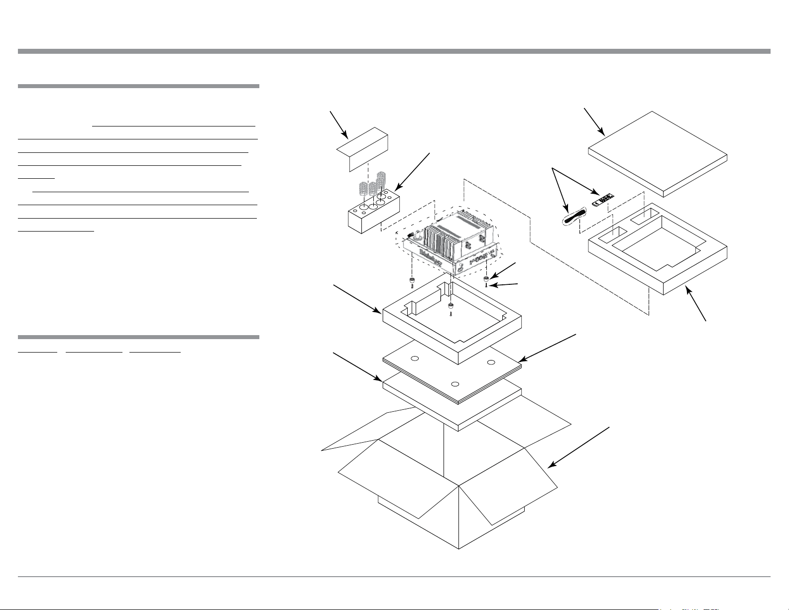
Packing Instructions
Packing Instructions
MA252 Packing Material List
Quantity Part Number Description
1 034580 Shipping carton
2 034582 Foam Top/Bottom
1 034577 Foam End Cap Pad Top
1 034578 Foam End Cap Pad Bottom
1 034581 Corrugated Bottom Pad
1 034579 Foam Insert (for protecting
the Tubes during shipping)
1 041855 Warning Sheet
4 400159 10-32 x 3/4 inch screw
4 163185 Feet
In the event it is necessary to repack the equipment
for shipment, the equipment must be packed exactly
as shown below. It is very important that the four feet
are attached to the bottom of the equipment. This will
ensure the proper equipment location on the bottom
foam pad. Failure to do this will result in shipping
damage.
To protect the tubes during shippment, the Foam
Insert removed from the MA252 needs to be re-insert-
ed. Follow the unpacking instructions on pages 4-5 in
the reverse order.
Use the original shipping carton and interior parts
only if they are all in good serviceable condition. If
a shipping carton or any of the interior part(s) are
needed, please call or write Customer Service Depart-
ment of McIntosh Laboratory, refer to page 2. Please
see the Part List for the correct part numbers.
Shipping Carton
Foam Top/Bottom
Foam Top/Bottom
Corrugated Bottom Pad
Foam End Cap Bottom
Foam End Cap Top
Warning Sheet
Foam Insert for Tubes
and Tube Shields
Feet
Screws
Accesories

The continuous improvement of its products is the
policy of McIntosh Laboratory Incorporated who
reserve the right to improve design without notice.
Printed in the U.S.A.
McIntosh Laboratory, Inc.
2 Chambers Street
Binghamton, NY 13903
www.mcintoshlabs.com
McIntosh Part No. 04175700