Ed :
Rev : Cod :
INSTRUCTION
07/20 GRLDEVETFK855S
00
3
DIMENSION DATA
Power Circuit: 220V~AC
Use in temperature:0-40℃
Real Speed:0.8-18KM/H
Incline:12 sections of motor incline
Max user weight :110kg
Distance range:0.00-99.9km
Calories:0-9999 Kcal
Time range:00:00-99:59(min)
Heart rate range:60-200 bpm
Running face:500*1380mm
Set up size:1760*790*1250mm
Folding size:1760*790*260mm
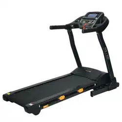
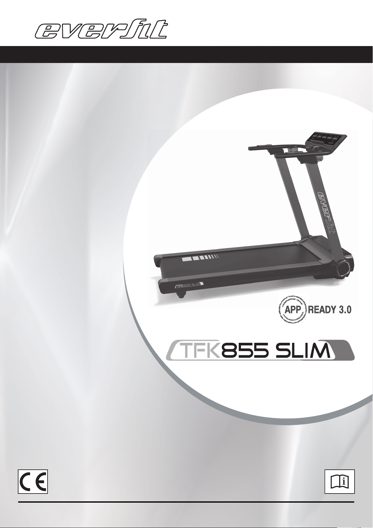
PRODUCT DESCRIPTION
Tablet Holder
Console
Bottle
holder
Folding Joint
Cover
Side Cover
Folding Lever
Solid Side Rail
Rear Support
Cover
Handrail
Buttons
Upright
Motor Upper Cover
Side Rail
Running Belt
End Cap
Lift Handle
4
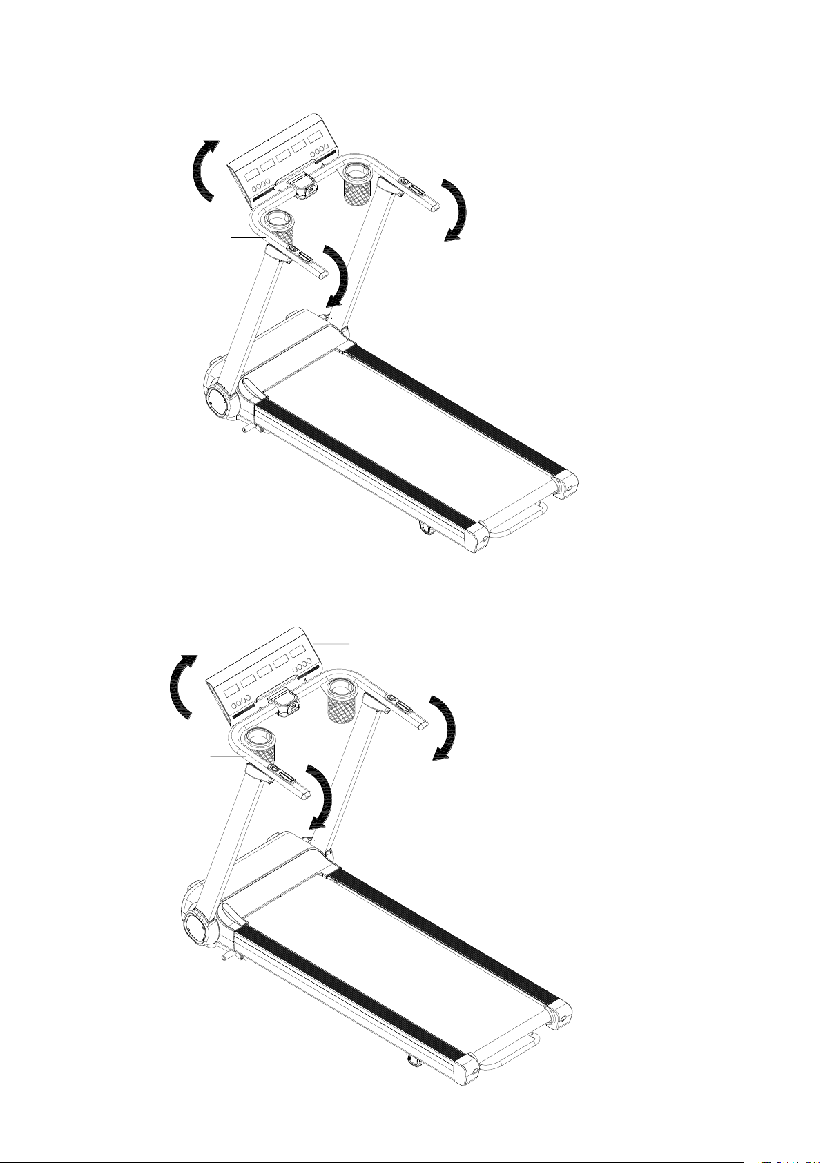
ASSEMBLY INSTRUCTIONS
ATTENTION: Do the following operations after checking all screws are tightened and everything is OK.
Before you use the treadmill, please read the instructions carefully.
STEP 1:Move out the treadmill unit from the packaging box, and place it on the flat
ground or floor.
STEP 2:Hold left and right #A4 handlebar and lift it up until hearing a “clock” sound for
locking the #A3L/ #A3R Uprights into position.
A4
A3R
A3L
5
STEP 3: Hold left and right #A4 Handlebar and push it down until hearing a “clock” sound
for lock it into position. Rotate the #B1 Console to the appropriate reading angle.
STEP 4: Plug in the #C15 Power Cord and insert the #C13 Safety Key.
A4
B1
A4
B1
7
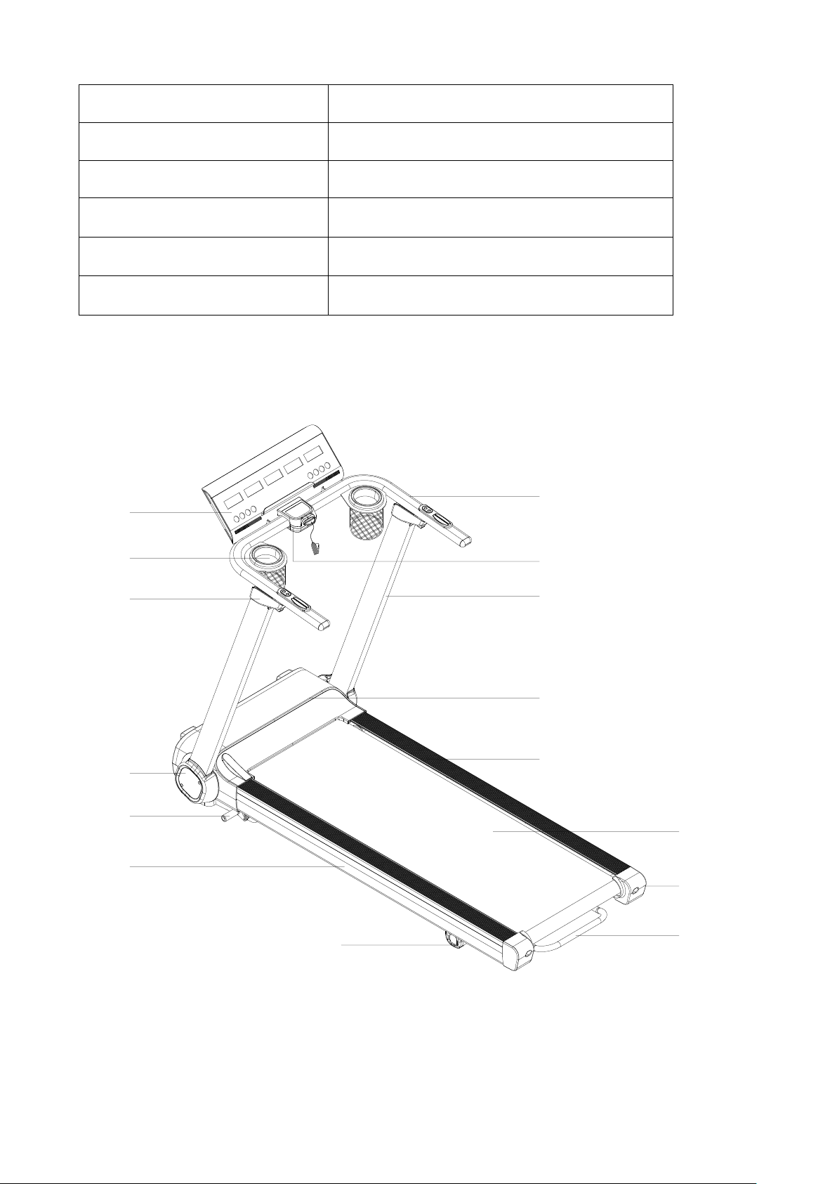
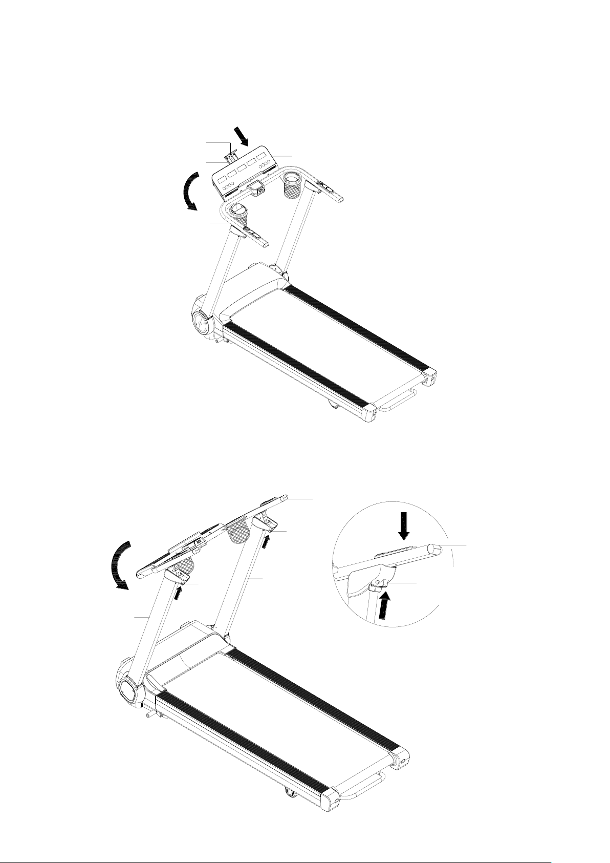
FOLDING INSTRUCTION
STEP 1: Rotate the #B1 Console backward to be horizontal with #A4 Handlebar.
STEP 2: Slightly push down the #A4 Handlebar and press #B100 Folding Button at the
same time. Once the #A4 Handlebar is un-locked, rotate it back to attach #A3L/ #A3R
Uprights.
B90
B1
B91
A4
B100
A3L
A4
B100
A3R
A4
B100
8
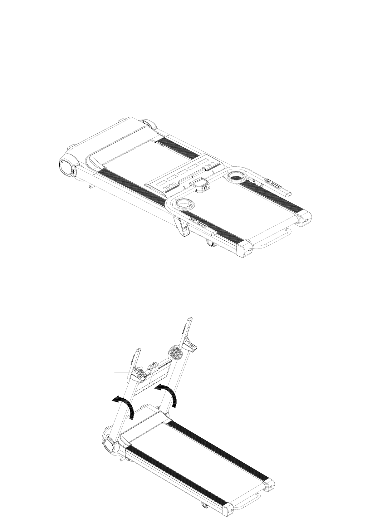
STEP 3: Step down #A44 Pedal Lever for auto folding process until #A3L/ #A3R to be
horizontal with running deck.
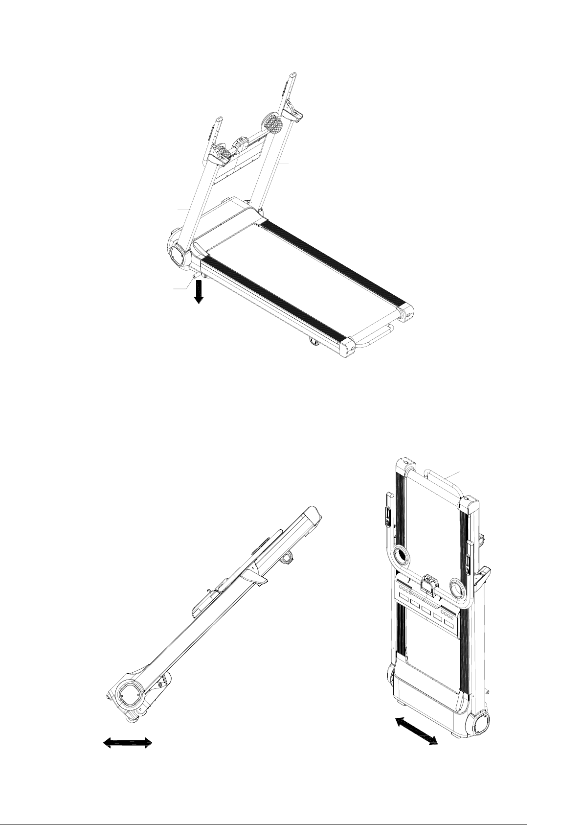
STEP 4: Hold #A1-H Lift Handle for transportation or lift one end of treadmill up to
standing position.
Figure A. Figure B.
A3R
A3L
A44
A1-H
9
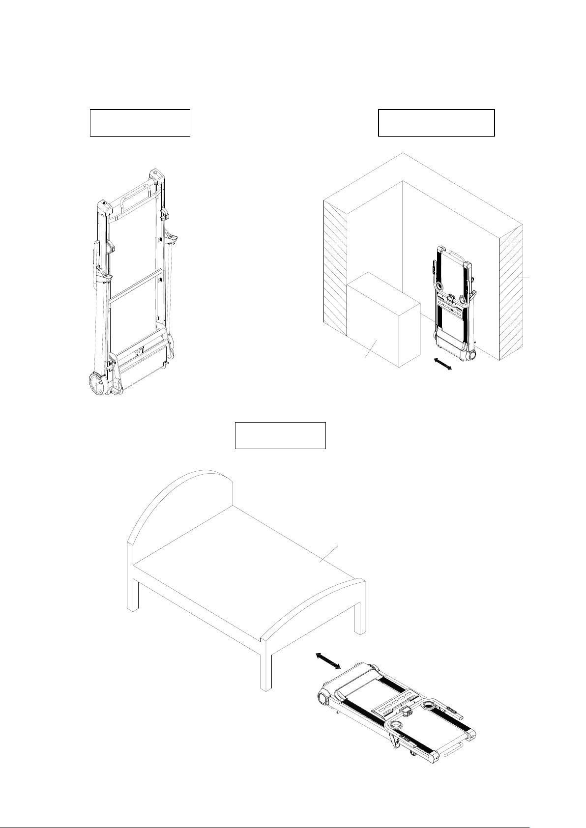
STEP 5: Place treadmill at standing position against wall for storage, or place it under the
bed for space saving. The height of treadmill is 26cm. If the space is less than 26cm
under your bed, please keep it somewhere else for storage.
Standing Position
Storage Against Wall
Place Under Bed
Bed
Wall
Cabinet

10
Operation Guide
1.1 WINDOW DISPLAY
1.2. START
Normal start after 3 seconds countdown
1.3 PROGRAM
1 manual mode, 3 countdown mode, 1 body fat program, 12 preset programs, 3 Users, and 3 HP
programs
1.4 SAFETY KEY FUNCTION
The window shows"---" when you take away the safety lock and the treadmill will stop quickly with
"didi" alarm noise. When you put the safety lock back on, the computer will display for 2 seconds and
the data will turn to “0.”
1.5 BUTTON FUNCTION
1.5.1 START AND STOP/PAUSE
“START”--When the treadmill is not running, press this button to start, speed is “0.8”
“STOP/PAUSE”--When the treadmill is running, press this button once to “Pause”. During “Pause” speed
and incline will go back to 0 and keep data. Press “Start” during pause mode to start again or Press
“Stop/Pause” again to stop and erase data.
1.5.2 “PROGRAM” BUTTON
When the treadmill is not running, press this button to cycle from manual mode to preset mode P1-P12,
body fat program, U1-U3, HP1-HP3

11
1.5.3 “MODE” BUTTON
When the treadmill is not running, press this button to choose between countdown modes: Time,
Distance, and Calories, press the Right/Left Quick Buttons on handrail “SPEED+/-” or “INCLINE+/-“ to
adjust the data. After that, press the “START” button to start this treadmill.
1.5.4“SPEED +/-“BUTTON
SPEED +/–, Adjust speed when treadmill start, the increment is 0.1km/time in kilometer.
Press the button more than 2 seconds, and it will go up or down automatically.
1.5.5 SPEED QUICK BUTTON
Press the speed quick button 3km/h,6km/h,9km/h, to adjust the speed directly when the treadmill
is running.
1.5.6 “INCLINE+/-” BUTTON
INCLINE +/ –, Adjust incline when treadmill start; the increment is 1 level/time.
Press the button more than 2 seconds, and it will go up or down automatically
1.5.7 INCLINE QUICK BUTTON
Press the incline quick button 3, 6, 9 to adjust the incline directly when the treadmill is running
1.6 DISPLAY FUNCTION
1.6.1 SPEED/CALORIES
Display treadmill speed and calories burned. Display will switch every 5 seconds.
1.6.2 STEP/PACE
Display how many steps taken on the treadmill. (Note: Step is counted based on the amp increase
when taking each step. If not much increase it will not count up. Step data is only for reference)
Display your pace. Pace is how long it takes you to complete 1KM during current speed.
Display will switch every 5 seconds.
1.6.3 TIME
Display the running total time or countdown time.

12
1.6.4 INCLINE/ALTITUDE
Display the current incline level
Display altitude you have ran, it is based on your incline level and how far you ran will show your MTS
Altitude.
1.6.5 PULSE/DISTANCE
Display your pulse data.
Display your total running distance or countdown distance.
1.6.6 ALL WINDOW DISPLAY DATA RANGE
TIME:0:00 – 99.59(MIN)
DISTANCE: 0.00 – 99.9(KM)
CALORIES: 0.0 – 9999 (C)
SPEED:0.8-20.0(km/h)
PULSE: 50 – 200 (BPM)
INCLINE:0 – 12
ALTITUDE:0 – 9999 MTS
STEPS:0 – 9999 STEPS
PACE:BASED ON CURRENT SPEED
1.7 PULSE FUNCTION
When the treadmill is running, hold the hand pulse for about 5 seconds, and it will display pulse data or
equip a wireless chest belt with a 5.3K Hz frequency. The pulse data range is 50-200 BPM. This data
is only for reference and can not be used as medical data.

13
1.8 PROGRAM EXERCISE CHART
TIME
MODE
SET TIME / 10= EVERY GRADE TIME
1
2
3
4
5
6
7
8
9
10
P1
SPEED
3
3
6
5
5
4
4
4
4
3
INCLINE
0
3
3
3
4
4
4
1
1
0
P2
SPEED
3
3
4
4
5
5
5
6
6
4
INCLINE
2
2
2
3
3
3
3
4
4
2
P3
SPEED
2
4
6
8
7
8
6
2
3
2
INCLINE
3
5
4
4
3
4
4
3
4
2
P4
SPEED
3
3
5
6
7
6
5
4
3
3
INCLINE
0
3
3
2
2
5
5
3
3
2
P5
SPEED
3
6
6
6
8
7
7
5
5
4
INCLINE
3
5
3
4
2
3
4
2
3
2
P6
SPEED
2
6
5
4
8
7
5
3
3
2
INCLINE
3
4
5
6
3
5
5
6
4
3
P7
SPEED
2
9
9
7
7
6
5
3
2
2
INCLINE
0
3
3
3
4
4
4
1
1
0
P8
SPEED
2
4
4
4
5
6
8
8
6
2
INCLINE
1
1
4
4
4
5
5
4
3
2
P9
SPEED
2
4
5
5
6
5
6
3
3
2
INCLINE
3
5
3
4
2
3
4
2
3
2
P10
SPEED
2
5
7
5
8
6
5
2
4
3
INCLINE
1
5
6
8
12
9
10
9
5
3
P11
SPEED
2
5
6
7
8
9
10
5
3
2
INCLINE
3
5
6
8
6
5
8
7
5
2
P12
SPEED
2
3
5
6
8
6
9
6
5
3
INCLINE
5
7
5
8
6
5
9
10
6
2

15
05 FAT ≤19 Under weight
FAT = (20---25) Normal weight
FAT = (25---29) Over weight
FAT ≥30 Obesity
1.12 USER PROGRAM
Besides 12 preset programs, there have 3 user-defined programs: U1, U2 and U3 Each user
program has 10 segments. The user can set the desired speed and incline .
Press "PROGRAM" button to choose U1 ,U2 or U3,press "MODE" button to enter setting
condition, then set the time of the first segment. Press "SPEED+" and "SPEED-" to set speed.
Press” INCLINE+” and “INCLINE-“ to set incline.
Press "MODE" button after you finished setting the first segment. The next workout segment
will flash, go through the same setup as you completed with segment one.
You must complete setting all 10 segments in order for your user program to begin.
1.13 HEART RATE CONTROL (HP) PROGRAM
IT IS RECOMMENDED THAT YOU USE A HEART RATE CHEST BELT (TRANSMITTER)
WHEN USING HRC PROGRAMS; HAND PULSE MAY NOT BE RELIABLE FOR HRC
PROGRAMS.
There are 3 Heart Rate Program programs (HP1-HP3) in total.
The parameter data setting order is “AGE” -> “Hear Rate data” -> “TIME”.
HRC: Detect user’s actual heart rate through wireless receiver and set different the heart rate
data as goal to adjust speed and incline during running.
1.13.1 After turning on the power, press “PROG” key to choose HRC function. HRC function
is turned on when “HRC” characters shown on the screen.
User can use “SPEED +/-“ to adjust age (data from 13 to 80) after seeing the “30” shown on
the screen.
1.13.2 Press “MODE” key to enter the setting of heart rate. The standard heart rate is fixed at
different data from HRC1 to HRC3. Heart rate data can be adjusted from 50 to 200. User can
use “SPEED +/-“ to adjust the data. (It’s recommended that standard heart rate data doesn’t

16
need to be changed for physical health condition.)
Formula is calculated as below:
HP1 is T.H.R =(220-age)x75%, Fastest speed 8KM
HP2 is T.H.R =(220-age)x85%, Fastest speed 9KM
HP3 is T.H.R =(220-age)x100%. Fastest speed 10KM
After finishing the setting of HRC data, user can press “MODE” key to modify the time. When
“TIME” window flashes, it displays the default time as 30:00 minutes, and user can press
“SPEED+/-“ to set up time.
1.13.3 Press “START” key to begin the workout (Remember you only can press “START” key
after all setting are completed.)
It’s suggested that user use wireless chest belt to detect the heart rate. If chest belt and hand
pulse are used at the same time, only data from chest belt will show up on the screen.
1.13.4 During the operating of HRC, speed and incline will adjust as below:
(1) If Target heart rate <THR-15,then the speed and incline will adjust automatically every 15
second, the SPEED will increase 0.8KM/h and incline add 1 section until they reach the max.
data.
(2) If THR-5>Target heart rate >=THR-15,then the speed and incline will adjust automatically
every 15 second, the SPEED will increase 0.4KM/h and incline add 1 section until they reach
the max. data.
(3) If THR+5>=Target heart rate >=THR-5,then the speed and incline will not change.
(4) If THR+15>=Target heart rate >=THR+5,then the speed will adjust automatically every 15
second, the SPEED will decrease 0.4KM/h and incline less1 section until they reach the min.
data
(5) If Target heart rate >=THR+15, then the speed and incline will adjust automatically every
15 second, the SPEED will decrease 0.8KM/h and incline less 2 section until they reach the
min. data

17
1.15 OTHERS
1.15.1 The system will enter into power saving mode automatically if there is no any action within 10
minutes under IDLE MODE and there is no display and backlight on the computer. Press any key to
resume the system.
1.15.2 Countdown time, countdown calorie and countdown distance, you can only set one of them at a
time. It will only start the last set countdown when you press start. The set parameter will start to
countdown and others display normal data..
1.15.3 On display – Distance covered, Calories burnt, Pulse reading, Body Fat test, Steps Counted,
Altitude ran are only for indicative purpose and may vary from machine to machine. Do not compare
these readings to a medical instrument.
1.15.4 You can set parameters in a cycle. Ex: Set time range is 5:00-99:00, when at 5:00 you
can hit “-” key and it will go to 99:00, when at 99:00 you can hit “+” and it will go to 5:00.
1.15.5 When the treadmill is running, press Mode+Program buttons at the same time for at
least 3 seconds to go from Scan mode to stay display one. Press again to stay at display two.
Press again to go back to scan mode Note: You will hear a beep if you successfully switch
the display modes.
1.15.6 When you remove safety key, you can press Mode+Program buttons at the same time
for at least 3 seconds to view treadmill’s Odometer. During this mode if you press
mode+program for 3 seconds it will reset the odometer. If want to leave mode without
resetting the data, just plug in the safety key.
1.16 Bluetooth music function:
Connect to the treadmill’s speakers using your phone or tablet. The treadmill’s Bluetooth
name would be under “QY-BTSP.” The treadmill’s speaker is set at highest volume, use your
phone or tablet to adjust the volume.

18
1.17 USB-Bluetooth App
The USB Slot on the side is meant for USB Bluetooth dongles. Treadmill is written to be able
to be compatible with Bluetooth dongle
23
MAINTENANCE INSTRUCTION
WARNING:Please make sure pull out the treadmill's power plug before cleaning or maintaining the
product.
CLEANSING:General cleaning or the unit will greatly prolong the treadmill's life.
Keep treadmill clean by dusting regularly. Be sure to clean the exposed part of the deck on either side
of the walking belt and also the side rails. This reduces the build up of foreign material underneath
the walking belt. Make sure the shoes are clean. The top of the belt may be cleaned with a wet soapy
cloth. Be careful to keep liquid away from inside the motorized treadmill frame or from underneath the
belt.
WARNING:Always unplug the treadmill from the electrical outlet before removing the motor
cover. At least once a year remove the motor cover and vacuum under the motor cover.
This treadmill's walking belt and deck are equipped with a pre-lubricated, low maintenance deck
system. Do not require adding lubrication.
We recommend lubrication of the deck according to the following timetable:
Light user (less than 3 hours/ week) Every 60 days
Medium user (3-5 hours/ week) Every 45 days
Heavy user (more than 5 hours/ week) Every 30 days
We suggest you buy lubricating oil from local distributors or contact our company directly.
Please note, any other maintenance please ask professionals for help.
24
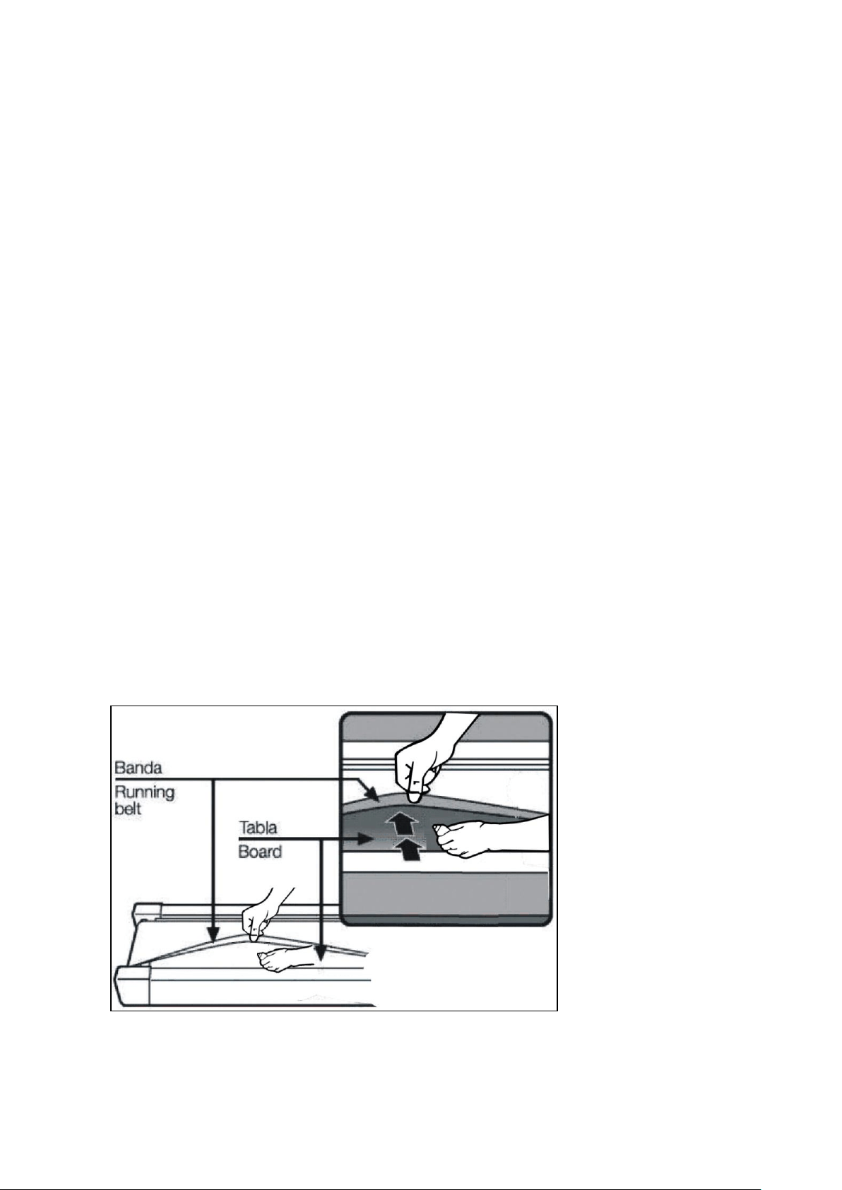
BELT ADJUSTMENT
Place treadmill on a level surface. Make treadmill run at approximately 6-8 km/h, observe the running
belt deviate condition.
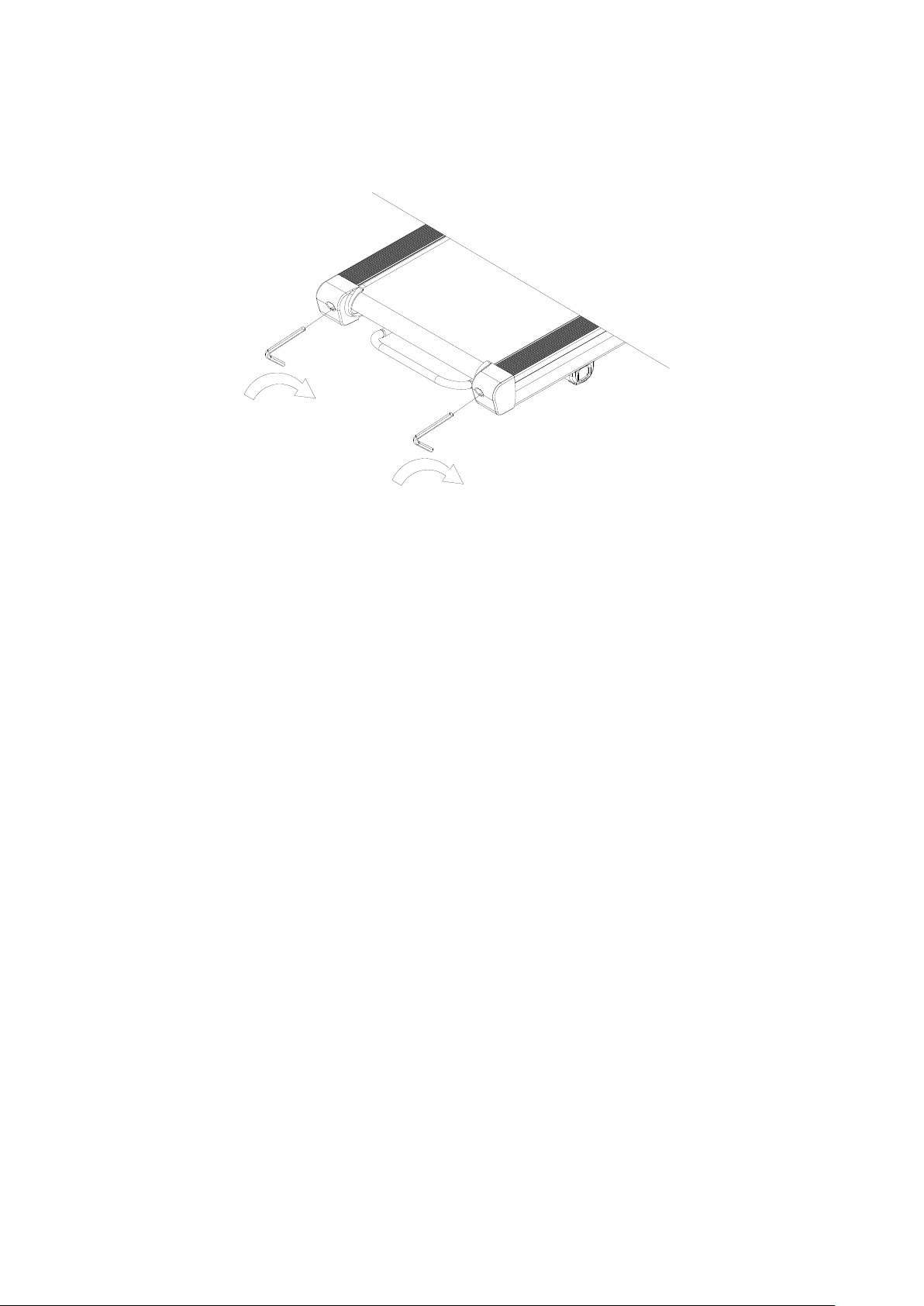
If the belt has drifted to the right, unplug the safety lock and power switch, and turn the right
adjusting bolt 1/4 turn clockwise, then insert the power switch and safety lock, make the treadmill
running, observe the running belt deviate condition.
Repeat above steps until the running belt be placed in the middle.
Once the treadmill belt swerving to the left, unplug the safety lock, turn off the power, then with the
left adjusting bolt clockwise rotation 1 / 4 laps, and turn on the safety lock and power to make treadmill
running, checking the deviation of the treadmill belt. Repeat the above
Steps until belt is centered.
The treadmill belt will gradually relax after above steps or after a period of time using, unplug the safety
lock, and turn off the power, with the two adjusting bolt clockwise rotation 1 / 4 laps, and turn on the
safety lock and power to make treadmill running, then standing on the belt to confirm the tightness.
Repeat the above steps until the belt moderate tightness.
25
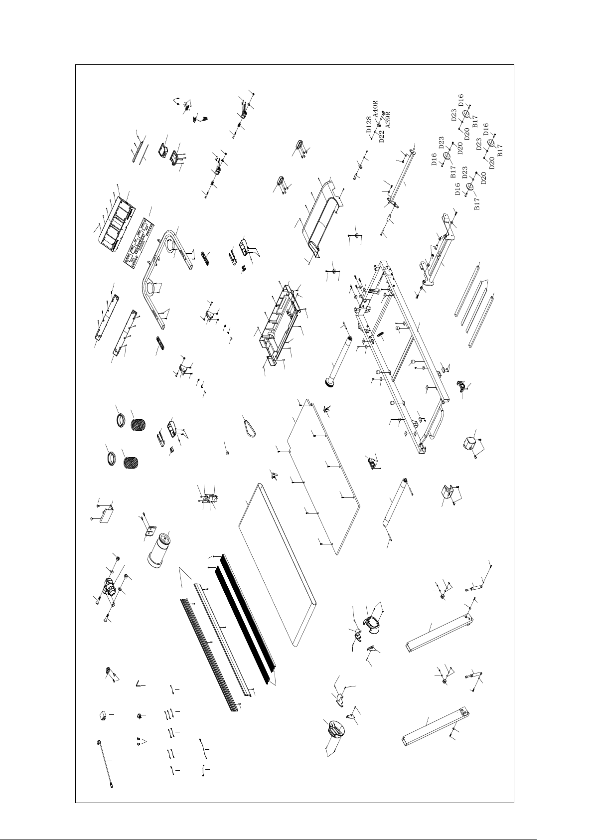
EXPLODED DRAWING
A1
A3L
A3R
A4
A16
A5
A7
A7
A11
A38
A39L
A40L
A41
A42
A43
A44
A45
A45
A46
A47
A34
C12
C1
C8
C34
C15
C23
C13
B1
C2
C5
C4
C3
C7
C41
C41
B89
B89
B89
B89
B1-5
B95
B96
B47
B55
B47
B87
C10
C11
C9
B51
B51
B97
B97
B98
B99
B100
B13
B14
B101
B11
B102L
B103L
B102R
B103R
B11
B104
B104
B31
B31
B27
B27
B105
B105
B106
B106
B16R
B16L
B107
B34
B44
D98
D121
D121
D99
D123
D124
D21
D7
D18
D21
D10
D18
D125
D23
A41
A43
D125
D23
D71
D13
D126
D127
A16
A47
D99
D123
D71
D13
D126
D127
D23
D64
D23
D64
D22
D129
D129
D20
D20
D130
B55
D130
A42
D64
D64
D64
D89
D73
D73
D89
D34
D34
D131
D131
D133
D133
D36
D60
D36
D36
D36
D52
D61
D134
D52
D52
D139
D52
B98
B99
B100
D52
D52
D52
D91
D91
D48
D91
D48
B101
D48
D48
D48
B107
B107
B52
D48
D45
D45
D135
D52
D44
D58
D2
D48
D48
D48
D48
D48
D48
D124
D136
D136
D139
D48
D48
B26
D72
C14
C27
C32 C31
C33
C17
C18
D34
D52
A13
A13
D52
A48
A48
D48
D48
D48
D48
D91
D91
D91
D91
D91
D91
B15
D52
D52
B5
B5
D54
B2
C22
C21
A6
D52
D52
D42
C20
D60
D60
D60

26
PARTS LIST
A. Welding and Metal Parts
NO.
DESCRIPTION
QTY
A1
Main Frame
1
A3L
Left Upright
1
A3R
Right Upright
1
A4
Handlebar
1
A5
Incline Bracket
1
A6
Filter Bracket
A7
Deck Support Tube
2
A11
Motor Base
1
A13
Belt Guide Bracket
2
A16
Handrail Folding Joint Bracket
2
A34
Safety Key Pin
2
A38
Pedal Lever Bracket
1
A39L
Left Bottom Hook
1
A39R
Right Bottom Hook
1
A40L
Left Connection Bracket
1
A40R
Right Connection Bracket
1
A41
Cylinder U-Shape Bracket
2
A42
Cylinder Spacer
2
A43
Cylinder Fixation Pin
2
A44
Pedal Lever
1
A45
Pedal Lever Spacer
2
A46
Incline Axle
2
A47
Stopper Pin
2
A48
PU Wheel Spacer
2

27
B. Plastic Parts
NO.
DESCRIPTION
QTY
B1
Console Set
1
B1-1
Overlay
1
B1-3
Console
1
B1-5
Tablet Holder
1
B2
Console Cover
1
B5
Console Back Cover
2
B11
Side Cover
2
B13
Motor Upper Cover
1
B14
Motor Bottom Cover
1
B15
Side Rail
2
B16L
Left End Cap
1
B16R
Right End Cap
1
B17
Transportation Wheel
4
B26
Deck Cushion
4
B27
Round Shape Cushion
4
B31
Rubber Pad
4
B34
EVA Pad (for Tablet Holder)
1
B44
EVA Pad (for Deck Support Tube)
2
B47
Console Rotation Washer
2
B51
Water Bottle Holder Ring
2
B52
Solid Side Rail
2
B55
Console Rotation Piece
2
B87
Safety Key Pin Cover
1
B89
Incline Bushing
4
B95
Button Platform Set
1
B96
Button Platform Bottom Cover
1
B97
Bottle Holder Net
2
B98
Folding Joint Cover
2
B99
Folding Joint Top Cover
2

28
B100
Folding Button
2
B101
Transportation Wheel Cover
2
B102L
Left Inner Side Cover 1
1
B102R
Right Inner Side Cover 1
1
B103L
Left Inner Side Cover 2
1
B103R
Right Inner Side Cover 2
1
B104
Second Transportation Wheel
2
B105
Rear Leg Support Cushion
2
B106
Rear Leg Support Cover
2
B107
Side Rail Fixing Piece
6
C. Electronic and Transmission Parts
NO.
DESCRIPTION
QTY
C1
Motor
1
C2
Running Belt
1
C3
Rear Roller
1
C4
Front Roller
1
C5
Running Deck
1
C7
Motor Belt
1
C8
Power Switch
1
C9
Controller
1
C10
Quick Buttons on Left Handlebar
1
C11
Quick Buttons on Right Handlebar
1
C12
Incline Motor
1
C13
Safety Key
1
C14
Single Cable 300 (Brown)
1
C15
Power Cord
1
C17
Lower Section Cable
1
C18
Medium Section Cable
1
C20
Magnetic Ring
1
C21
Inductor
1
C22
Filter
1

29
C23
Overload Protector
1
C27
Single Cable 300 (Blue)
1
C31
Short Single Cable 150 (Brown)
3
C32
Short Single Cable 150 (Blue)
2
C33
Grounding Wire
1
C34
Power Switch
1
C41
Cylinder
2
D. Hardware Parts
NO.
DESCRIPTION
QTY
D2
Allen Wrench T6
1
D7
Round Head Hex Bolt M10X65
1
D10
Round Head Hex Bolt M10X45
1
D13
Round Head Hex Bolt M8X15
2
D16
Round Head Hex Bolt M8X45
4
D18
Nylon Nut, M10
2
D20
Nylon Nut, M8
6
D21
Flat Washer, M10
2
D22
Flat Washer, M6
2
D23
Flat Washer, M8
8
D34
Socket Head Cap Bolt M8X60
4
D36
Hex Head Hex Bolt M6X25
4
D39
Hex Sunk Head Hex Bolt M6X43
4
D42
Cross Washer Head Bolt M4X10
2
D44
Cross Washer Head Bolt M5X12
2
D45
Cross Washer Head Bolt M5X15
4
D48
Cross Washer Head Self-drilling Tapping Bolt ST4.2X19
34
D52
Cross Pan Head Tapping Bolt ST4.2X16
31
D54
Cross Pan Head Tapping Bolt ST4.2X30
6
D58
Cross Sunk Head Self-drilling Tapping Bolt ST3.5X16
2
D61
Phillips Head Blunt Screw, ST4.2x19mm
4
D64
Round Head Hex Bolt M8X20
6

30
D71
Countersunk Head Hex Bolt M8X15
2
D72
Socket Head Cap Bolt M8X25
4
D73
Socket Head Cap Bolt M8X12
2
D89
Washer, M8
2
D91
Cross Pan Head Self-drilling Tapping Bolt bolt ST4.2X19
12
D98
Extension Spring
1
D99
Compression Spring
2
D121
Console Compression Spring
2
D123
C Ring ∮5
2
D124
C Ring ∮6
4
D125
Round Head Hex Bolt M8X12
2
D126
Round Head Hex Bolt M8X37
2
D127
Thin Nylon Nut, M8
2
D128
Round Head Hex Bolt M6X12
2
D129
Round Head Hex Bolt M8X67
2
D130
Cross Sunk Head Self-drilling Tapping Bolt ST4.2X19
8
D131
Flat Head Hex Bolt M8X22
2
D133
Socket Head Cap Bolt M6X10
2
D134
Cross Head Tapping Bolt ST4.2X10
6
D135
Round Head Hex Bolt M6X10
4
D136
Cross Head Self-drilling Tapping Bolt ST4.2X19
8
D139
Cross Sunk Head Self-drilling Tapping Bolt ST4.2X25
4

GARLANDO SPA
Via Regione Piemonte, 32 - Zona Industriale D1
15068 - Pozzolo Formigaro (AL) - Italy
www.evert.it - info@evert.it