Planning aid
International collection
Laundry room appliances
2019
V-ZUG Ltd
V-ZUG Ltd, Industriestrasse 66, CH-6302 Zug
[email protected], www.vzug.com
Planning aid
International collection
Laundry room appliances
J001062-R16
30.04.19
2
Note on content
Please note
This planning aid applies to the specified model numbers only. Older planning aids for earlier generation models may be requested in
electronic form from our Customer Services.
This planning aid is not to be used as installation instructions! The regulations and instructions binding for the appliance installation
are to be obtained from the installation instructions packed with the appliances. The installation instructions can also be downloaded
from the internet from www.vzug.com/b2b.
Modifications
Text, diagrams and data correspond to the technical standard of the appliances at the time this planning aid went to press. The right
to make technical modifications for the purpose of the further development of the appliances is reserved. The German, English,
French and Italian versions are binding. V-ZUG accepts no liability for translations in other languages.
Symbols used
Denotes important safety precautions.
Failure to observe said precautions can result in injury or in damage to the appliance or fittings!
► Indicates an instruction.
• Indicates a list.
Information and precautions that should be observed.
Supplementary documents
In this planning aid, occasional reference is made to supplementary documents. These documents can be requested from the Head
Office in Zug by sending an e-mail to [email protected].
Useful links
• www.vzug.com
• www.vzug.com/b2b
• www.lifestyle.vzug.com
Key to country groups
Country group Country code
(in accordance with ISO 3166)
Country group Country code
(in accordance with ISO 3166)
A EU European Union
TR Turkey
IL Israel
LB Lebanon
D AU Australia
NZ New Zealand
B GB Great Britain E RU Russia
UA Ukraine
C HK Hong Kong
SG Singapore
F CN China
V-ZUG Ltd
V-ZUG Ltd, Industriestrasse 66, CH-6302 Zug
[email protected], www.vzug.com
Planning aid
International collection
Laundry room appliances
J001062-R16
30.04.19
3
Explanation of terms
CRO4T
W
C
L
R
Colour white
Colour ChromeClass
Left-hinged door
Right-hinged door
Design
W
O
Heat pump
OptiDos
AW
AT
RB
Features
AW
OptiDos
2T
4T
6T
V2000
V4000
V6000
Hero name
Segment
ProductNameFunction
AdoraWash
AdoraDry
RefreshButler
AdoraWash
V4000 OptiDos
Combined washer-dryer
Adorina
Combo
Super
Appliance
Appliance brand
Appliance type
Convenience level
WAK
AN
C
S
SCAN
WAK

V-ZUG Ltd
V-ZUG Ltd, Industriestrasse 66, CH-6302 Zug
[email protected], www.vzug.com
Planning aid
International collection
Laundry room appliances
J001062-R16
30.04.19
4
Contents
1 Appliance overview 5
1.1 Validity......................................................................................................................................................................................5
1.2 Washer-dryer towers................................................................................................................................................................5
2 Electrical connections 6
2.1 General operating conditions ...................................................................................................................................................6
2.2 Using residual current devices in house wiring system / fault current......................................................................................6
3 Plumbing in 7
3.1 Washing machines...................................................................................................................................................................7
3.2 Tumble dryers ..........................................................................................................................................................................8
3.3 Washer-dryer combination .......................................................................................................................................................9
3.4 Combined washer-dryer.........................................................................................................................................................12
4 Washing machines 13
4.1 Electrical connection data ......................................................................................................................................................13
4.2 Dimensions ............................................................................................................................................................................13
4.3 Installation ..............................................................................................................................................................................14
4.4 Positioning.............................................................................................................................................................................. 14
5 Tumble dryers 16
5.1 Electrical connection data ......................................................................................................................................................16
5.2 Dimensions ............................................................................................................................................................................16
5.3 Installation ..............................................................................................................................................................................17
5.4 Positioning.............................................................................................................................................................................. 18
6 Washer-dryer towers 20
6.1 Installation ..............................................................................................................................................................................20
6.2 Positioning.............................................................................................................................................................................. 20
7 Combined washer-dryer 22
7.1 Electrical connection data ......................................................................................................................................................22
7.2 Dimensions ............................................................................................................................................................................22
7.3 Installation ..............................................................................................................................................................................23
7.4 Positioning.............................................................................................................................................................................. 24
8 Textile care system 25
8.1 Electrical connection data ......................................................................................................................................................25
8.2 Dimensions ............................................................................................................................................................................25
8.3 Installation ..............................................................................................................................................................................26
8.4 Positioning.............................................................................................................................................................................. 26
9 Accessories 31
9.1 Washing machines.................................................................................................................................................................31
9.2 Tumble dryers ........................................................................................................................................................................31
9.3 Textile care system ................................................................................................................................................................31
9.4 Combined washer-dryer.........................................................................................................................................................31
V-ZUG Ltd
V-ZUG Ltd, Industriestrasse 66, CH-6302 Zug
[email protected], www.vzug.com
Planning aid
International collection
Laundry room appliances
J001062-R16
30.04.19
5
1
Appliance overview
1.1
Validity
The model number corresponds to the first alphanumerics of the serial number SN (or FN) on the identification plate.
Product Model number Product Model number
Washing machines Tumble dryers
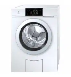
AdoraWash V2000 11021 AdoraDry V2000 12011
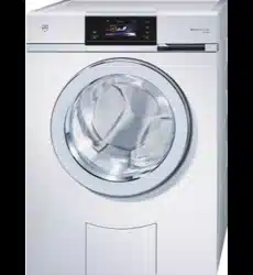
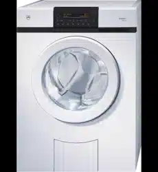
AdoraWash V4000 11023 AdoraDry V6000 12013
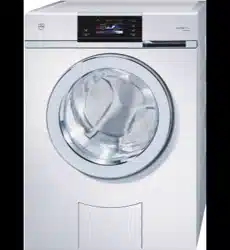
AdoraWash V6000 11025
Textile care system
Combined washer-dryer RefreshButler V6000 14003
Adorina CS 11018
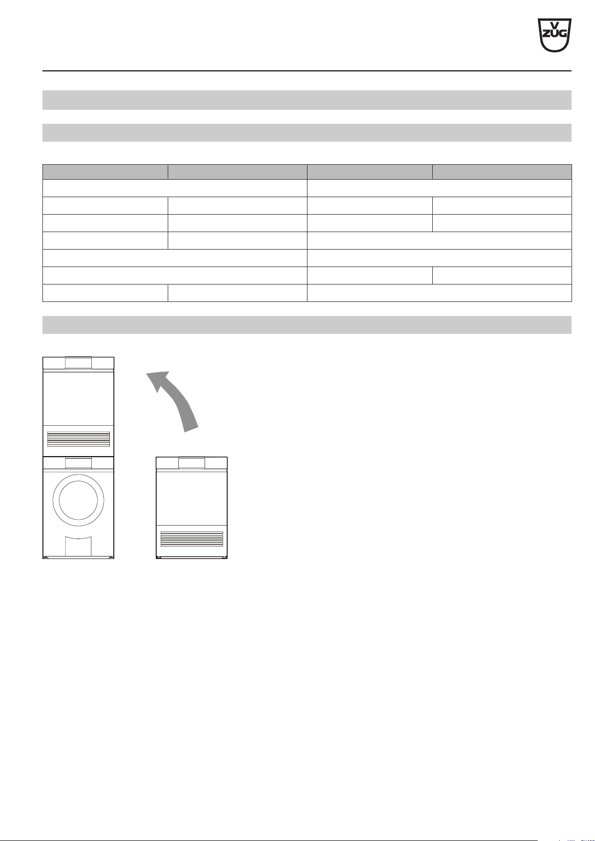
1.2
Washer-dryer towers
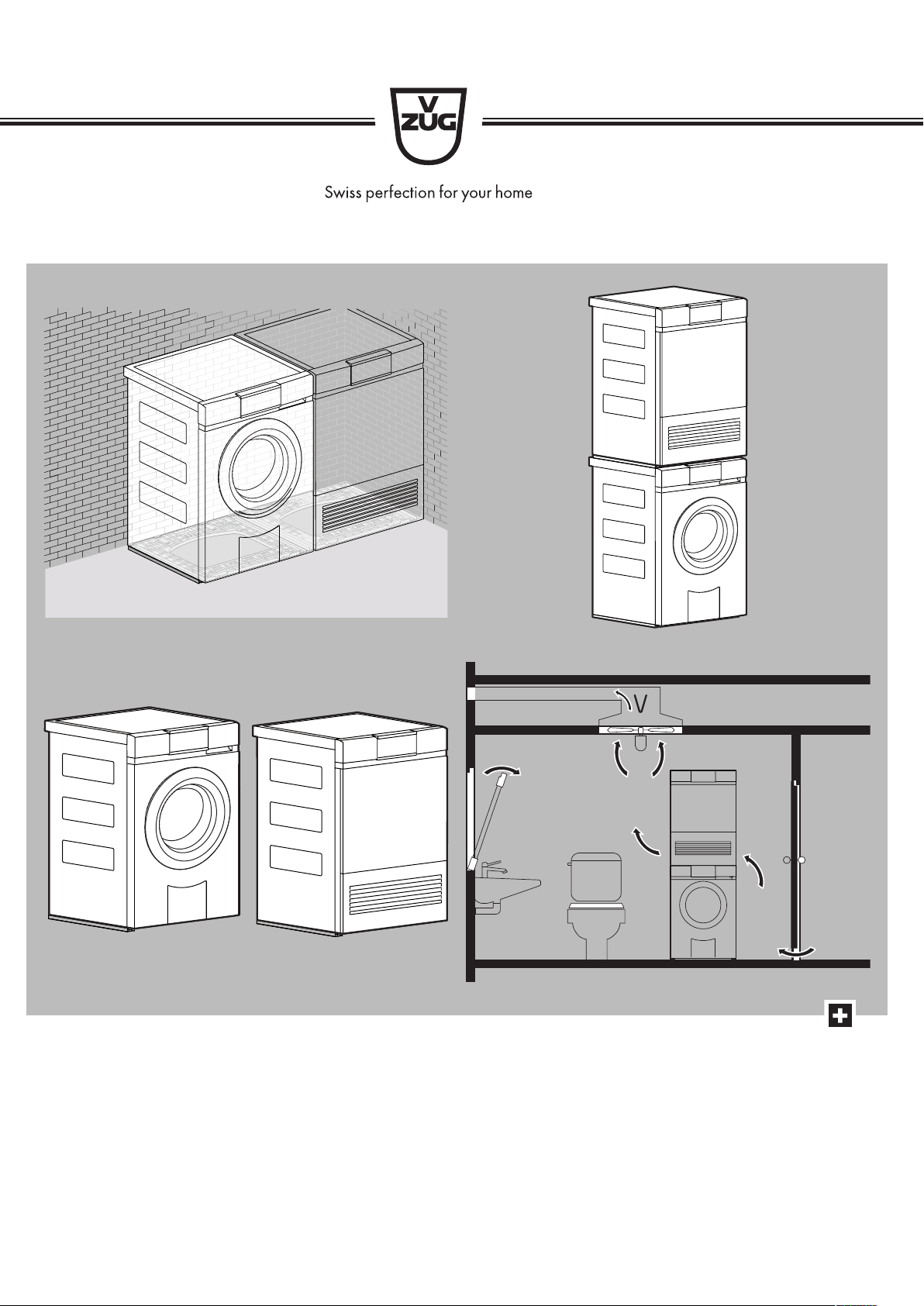
Washing machines and tumble dryers with the same level of convenience can be combined to form a washer-dryer tower.
AdoraWash AdoraDry
V-ZUG Ltd
V-ZUG Ltd, Industriestrasse 66, CH-6302 Zug
[email protected], www.vzug.com
Planning aid
International collection
Laundry room appliances
J001062-R16
30.04.19
6
2
Electrical connections
Electrical connections must be carried out by qualified experts in accordance with the guidelines and standards for low-
voltage installations and the specifications of the local electricity supply companies.
A plug-in appliance may only be connected to a socket outlet with earthing contact, installed according to specifications. An
all-pole mains isolating device with 3 mm contact opening should be provided in the house wiring system. Switches, plug
and socket devices, circuit breakers and fusible cut-outs which are accessible after installation and which have all-poles
switching are permissible as isolating devices. Effective earthing and separately installed neutral and earth conductors en-
sure safe and fault-free operation. After installation, live parts and cables with basic insulation must not be accessible.
Check old installations.
Electrical connections must be made by qualified personnel.
2.1
General operating conditions
Detailed information on the electrical connection data can be found at the beginning of each section.
Value Country group * Nominal value Minimum Maximum
Voltage A, B, C (SG), D, E 230 V 207 V 253 V
C (HK), F 220 V–240 V 198 V
Voltage A, B, C (SG), D, E 400 V 360 V 440 V
C (HK), F 380 V–413 V 342 V
Frequency A, B, C, D, E, F 50 Hz sinusoidal 49 Hz sinusoidal 51 Hz sinusoidal
* Key (see page 2)
• Short duration frequency variation in the mains: ±1 Hz
• Long duration frequency stability in the mains (for synchronous clocks): ± 10 ppm
• Protection type IP: IP-X4
• If used at an altitude of over 2,000 metres, a reduced performance must be expected.
2.2
Using residual current devices in house wiring system / fault current
Washing machines have an inherently high fault current. The values can be affected by various factors and vary widely. In accord-
ance with the norm, fault currents of up to approximately 10 mA per appliance are permissible. The values are measured in the warm
operating state.
If residual current devices (RCDs) are used in the house wiring system, we recommend that the above-mentioned appliances have
their own RCD protection, separate from the power supply for the rest of the system. The tripping current of the RCD should be se-
lected to be 30 mA or higher.
V-ZUG Ltd
V-ZUG Ltd, Industriestrasse 66, CH-6302 Zug
[email protected], www.vzug.com
Planning aid
International collection
Laundry room appliances
J001062-R16
30.04.19
7
3
Plumbing in
3.1
Washing machines
Comply with the regulations laid down by the local water supply authority for the layout of the supply pipe and drainage.
General operating conditions
Value Nominal value Minimum Maximum
Mains pressure
(0.1 MPa = 1 bar)
Static 0.3 MPa 0.1 MPa 1.0 MPa
Flowing – 0.08 MPa 1.0 MPa
Water hardness
1
– 0.5 °fH 50 °fH
Water inlet temperature Cold water – 5 °C 35 °C
Water inlet G¾" – –
Drainage cross-section ø internal 57 mm (on-site) ø internal min. 19 mm –
1
For special cases with water hardness in excess of 50 °fH, an external water softener is recommended.
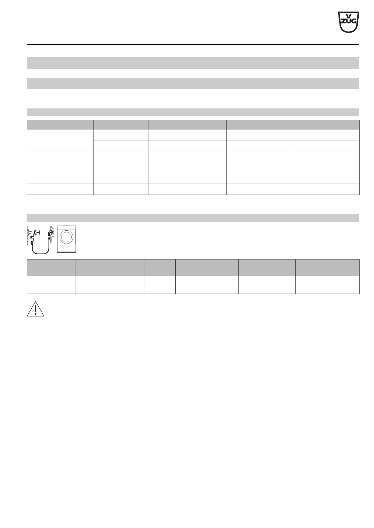
Water inlet
Appliance Hose Length Connection Optimal working
pressure
Possible pressure
range
AdoraWash
V2000–V6000
Inlet hose with Aquastop 1.25 m G¾" 0.3 MPa ( 3 bar) 0.1–1.0 MPa (1–10 bar)
Connection to a mixer tap or a continuous flow heater is not permitted!
V-ZUG Ltd
V-ZUG Ltd, Industriestrasse 66, CH-6302 Zug
[email protected], www.vzug.com
Planning aid
International collection
Laundry room appliances
J001062-R16
30.04.19
8
Water outlet
V-ZUG does not supply or install drain-traps. Follow the drain-trap manufacturer’s instructions.
Hose clamp
Drain hose
Rubber connector
Cannot shorten drainage hose!
Shorten drainage hose to
required length.
≤1200
≤700
1.5 m
ø interior 21.5 mm
ø exterior 28.0 mm
≥350
Hose clip (bend)
Appliance Hose Length Connection Pumping height of drain pump from floor
AdoraWash
V2000–V6000
Corrugated plastic hose 1.5 m ø internal 21.5 mm ≥1200mm
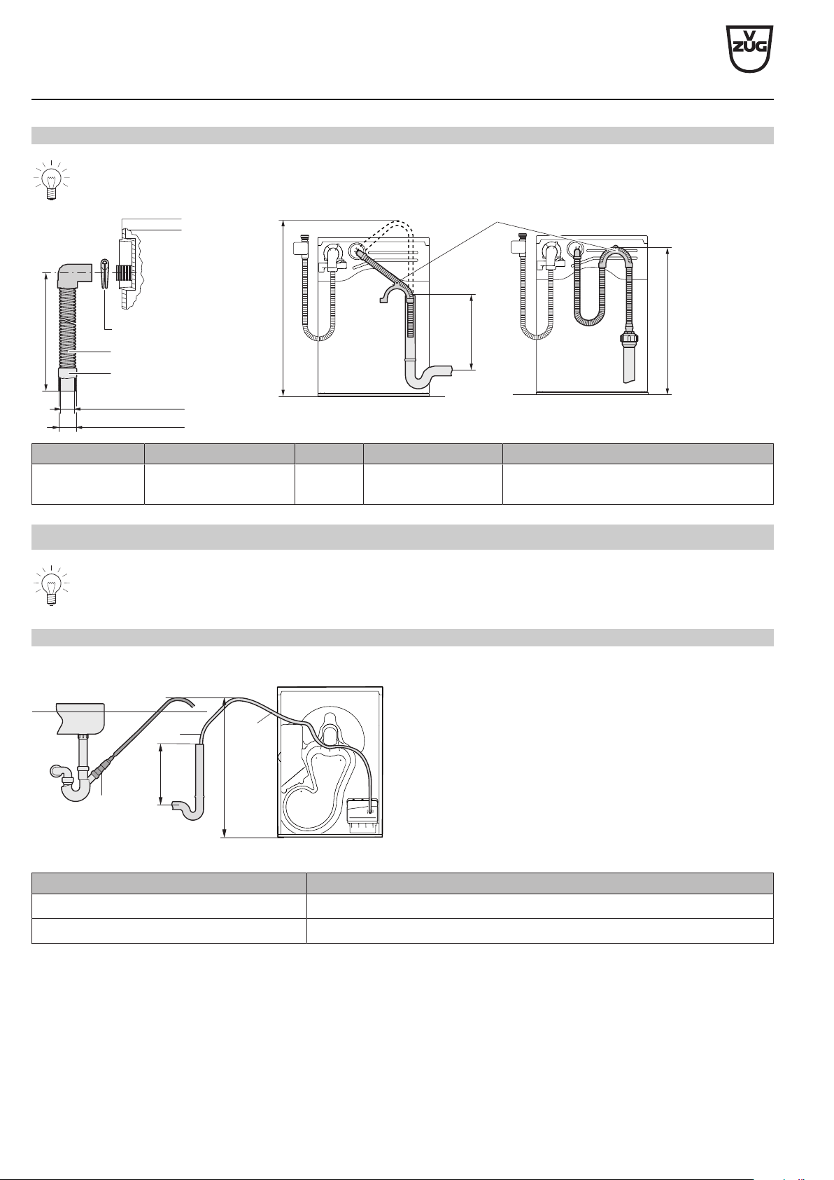
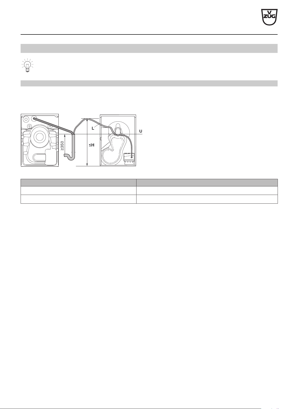
3.2
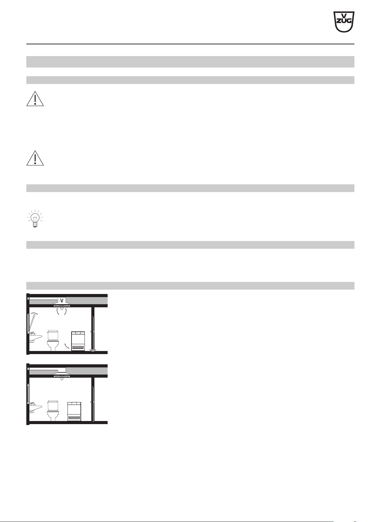
Tumble dryers
V-ZUG does not supply or install drain-traps. Follow the drain-trap manufacturer’s instructions.
Direct drainage
AdoraDry
2
1
≤H
≥350
U
L
1 Connection to sink drain trap, set W53070
2 Condensate drain kit W56298 (series standard)
► Use a drain trap with an open-top fixed upright outflow pipe.
► For a connection to sink drain trap, position the drain hose
above the overflow line U.
AdoraDry V2000, V6000
L: Hose length from pump to H ≤1.5m
H: Pumping height of drain pump from floor ≤1200mm
V-ZUG Ltd
V-ZUG Ltd, Industriestrasse 66, CH-6302 Zug
[email protected], www.vzug.com
Planning aid
International collection
Laundry room appliances
J001062-R16
30.04.19
9
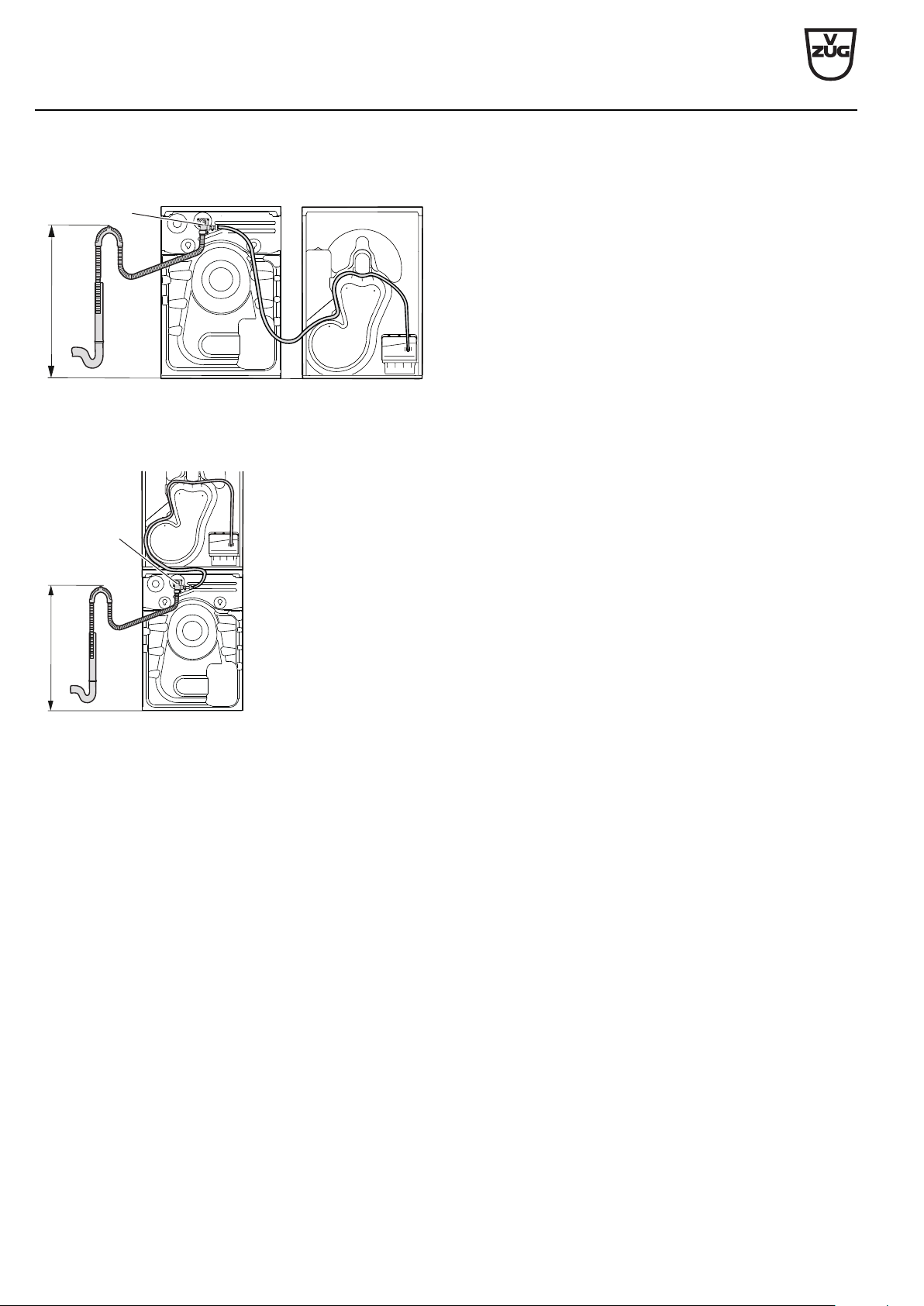
3.3
Washer-dryer combination
V-ZUG does not supply or install drain-traps. Follow the drain-trap manufacturer’s instructions.
Connection to drain trap with open-top fixed upright outflow pipe
Appliances installed side by side with separately routed drainage pipe
AdoraWash & AdoraDry
► Position the drain hose from the tumble dryer above the
overflow line U.
AdoraDry V2000, V6000
L: Hose length from pump to H ≤1.5m
H: Pumping height of drain pump from floor ≤1200mm
V-ZUG Ltd
V-ZUG Ltd, Industriestrasse 66, CH-6302 Zug
[email protected], www.vzug.com
Planning aid
International collection
Laundry room appliances
J001062-R16
30.04.19
10
Appliances installed side by side with combi drainage set
AdoraWash & AdoraDry
≤700
2
2 Combi drainage set W55969
► Fix hose end with hose support.
► Secure drain hose on tumble dryer so that it cannot kink.
Washer-dryer tower with combi drainage set
AdoraWash & AdoraDry
≤700
2
2 Combi drainage set W55969
► Fix hose end with hose support.
V-ZUG Ltd
V-ZUG Ltd, Industriestrasse 66, CH-6302 Zug
[email protected], www.vzug.com
Planning aid
International collection
Laundry room appliances
J001062-R16
30.04.19
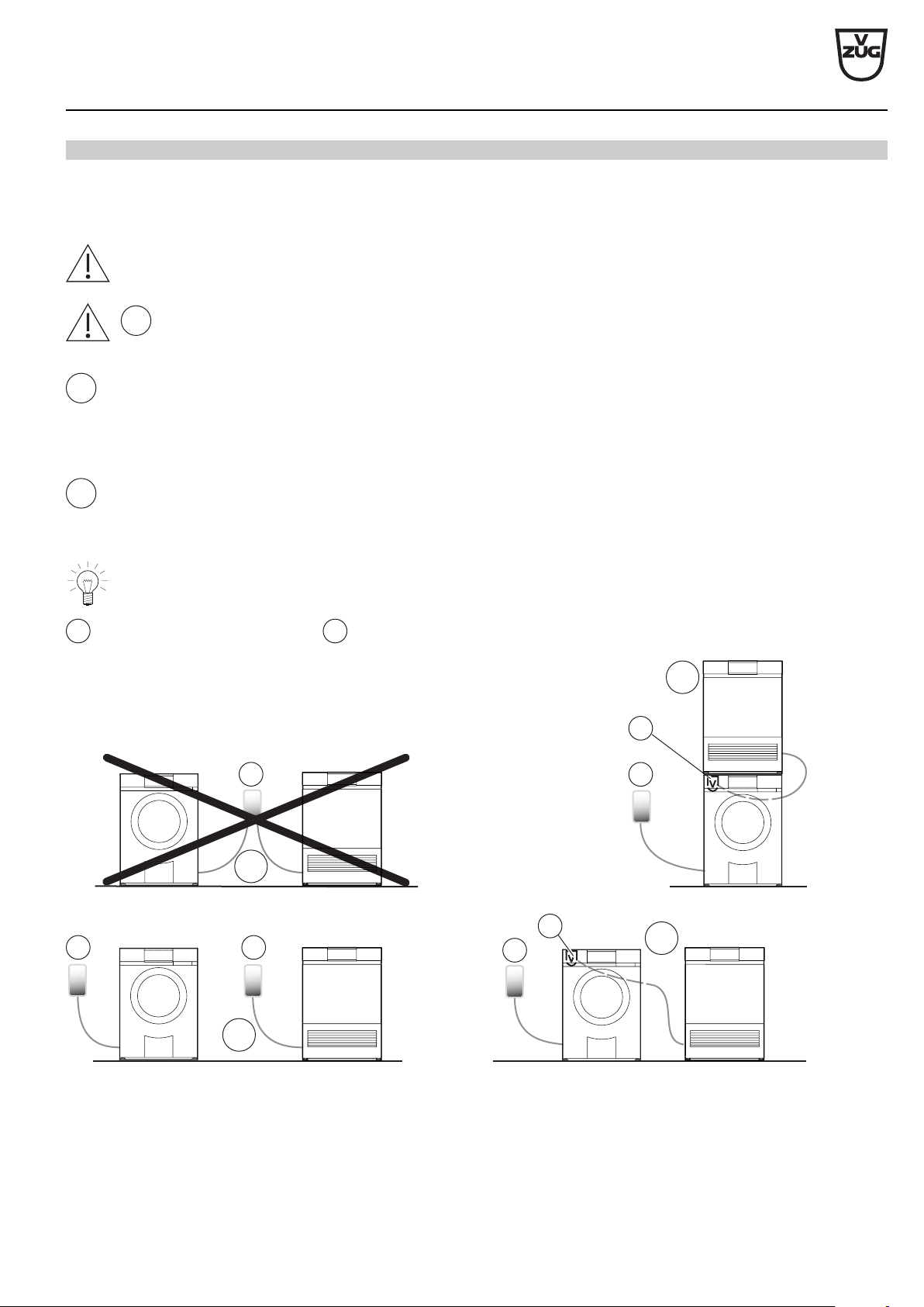
11
Connection to concealed drain-trap
V-ZUG does not supply or install concealed drain-traps. Unused connections to the concealed drain-trap must be sealed off. Where
possible, the washing machine and tumble dryer should be connected to a separate concealed drain-trap. Secure drain hoses with a
clamp (not included in the scope of delivery).
Water must be prevented from flowing from the washing machine into the tumble dryer!
1
A washing machine and tumble dryer may only be connected to the same concealed drain-trap if the two appliances
remain hydraulically separate from one another.
2
Washer-dryer tower or washing machine and tumble dryer installed side by side with combi drainage set
The AdoraDry V2000, V6000 tumble dryers can be retrofitted with the accessory combi drainage set (article no. W55969). It permits
the water outlet of a washing machine and a tumble dryer into one water outlet (concealed drain-trap). The water from the tumble
dryer is pumped by the pump into the water outlet of the washing machine.
3
Washing machine and tumble drying installed side by side
If a tumble dryer is installed side by side with the appropriate washing machine, each appliance must be connected to a separate
concealed drain-trap.
The combi drainage set V may be used if there is only one concealed drain-trap X.
V
Combi drainage set
W55969
X
Concealed drain-trap
1
3
2
2
X
V
V
X
X
X
X
Washing machine Tumble dryer
V-ZUG Ltd
V-ZUG Ltd, Industriestrasse 66, CH-6302 Zug
[email protected], www.vzug.com
Planning aid
International collection
Laundry room appliances
J001062-R16
30.04.19
12
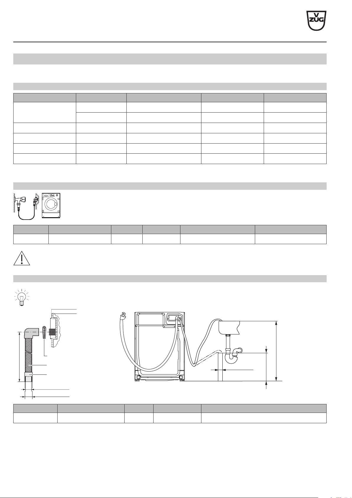
3.4
Combined washer-dryer
Comply with the regulations laid down by the local water supply authority for the layout of the supply pipe and drainage.
General operating conditions
Value Nominal value Minimum Maximum
Mains pressure
(0.1 MPa = 1 bar)
Static 0.3 MPa 0.05 MPa 0.9 MPa
Flowing – – 0.9 MPa
Water hardness
1
– 0.5 °fH 50 °fH
Water inlet temperature Cold water – 5 °C 35 °C
Water inlet G¾" – –
Drainage cross-section ø internal 57 mm (on-site) ø internal min. 19 mm –
1
For special cases with water hardness in excess of 50 °fH, an external water softener is recommended.
Water inlet
Appliance Hose Length Connection Optimal working pressure Possible pressure range
Adorina CS Inlet hose with Aquastop 2.2 m G¾" 0.3 MPa (3 bar) 0.05–0.9 MPa (0.5–9 bar)
Connection to a mixer tap or a continuous flow heater is not permitted!
Water outlet
V-ZUG does not supply or install drain-traps. Follow the drain-trap manufacturer’s instructions.
≤900
≥500
≥ø40.0
Hose clamp
Drain hose
Rubber connector
2200
ø interior 20.0
ø exterior 28.0
Appliance Hose Length Connection Pumping height of drain pump from floor
Adorina CS Corrugated plastic hose 2.2 m ø internal 20 mm ≥900mm
V-ZUG Ltd
V-ZUG Ltd, Industriestrasse 66, CH-6302 Zug
[email protected], www.vzug.com
Planning aid
International collection
Laundry room appliances
J001062-R16
30.04.19
13
4
Washing machines
4.1
Electrical connection data
Appliance Country group * Mains connection Rated load Fuse Mains cable
AdoraWash V6000 A 230V~ 50Hz 3500W 16A with plug 1.8 m
C (SG), E 230V~ 50Hz 2100W 10A
C (HK), D, F 220–240V~ 50Hz 2100W 10A
AdoraWash V4000 A 230V~ 50Hz 3500W 16A with plug 1.8 m
E 230V~ 50Hz 2300W 10A
AdoraWash V2000 A, C (SG), E 230V~ 50Hz 2300W 10A with plug 1.8 m
C (HK), D 220–240V~ 50Hz 2300W 10A
* Key (see page 2)
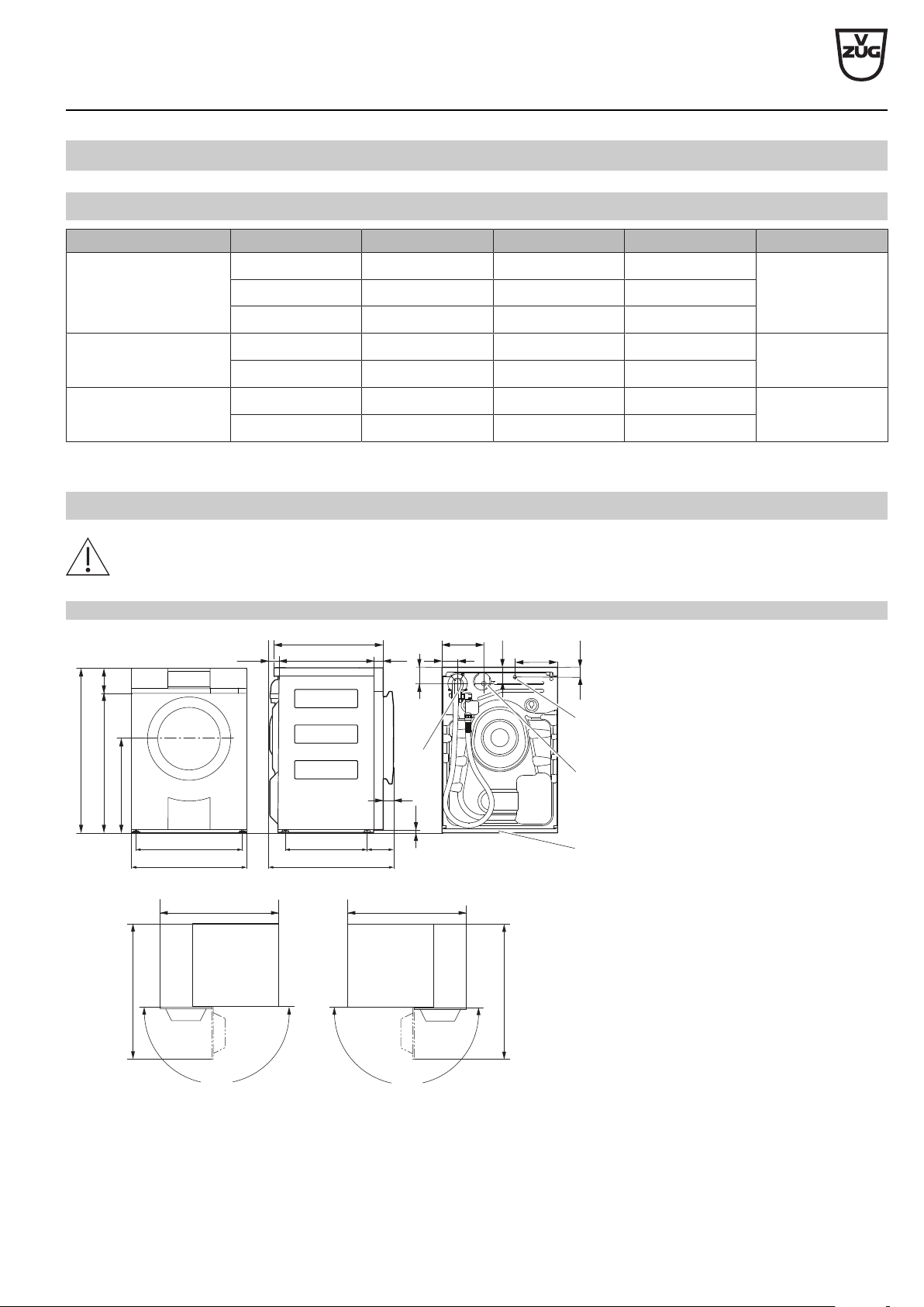
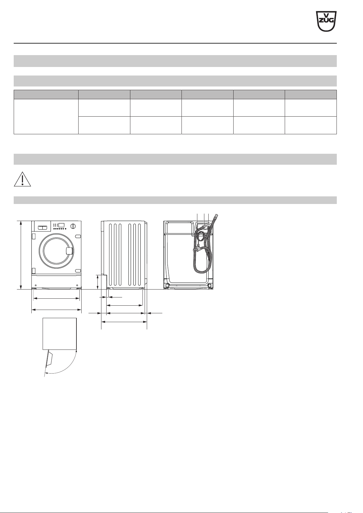
4.2
Dimensions
The stated dimensions do not include distances from walls. To prevent disturbing noise and vibration the appliances must
not come into contact with the surrounding walls of their installation location.
AdoraWash V2000, V4000, V6000
213
80
72
160
45
180°
180°
957 957
595
33
625
850
(125)
500
577
500 50
(42)
15
84.5
725
4
2
3
1
550
458 104
Open door 1059*
Left-hand hinged door
Right-hand hinged door
Open door 1059*
1 Cold water connection;
inlet hose with Aquastop,
Length: 1.25 m, G¾"
2 Drainage hose connection with elbow,
Length: 1.5 m
Pumping height of drain pump: 1.2 m
3 Electrical connection cable outlet,
Length: 1.8 m, with plug
4 Installation plate
* In order that the detergent dispenser
drawer can be used without obstruction
and be taken out for cleaning, the clear-
ance space must be observed across the
entire front of the appliance.
V-ZUG Ltd
V-ZUG Ltd, Industriestrasse 66, CH-6302 Zug
[email protected], www.vzug.com
Planning aid
International collection
Laundry room appliances
J001062-R16
30.04.19
14
4.3
Installation
General condition
All Adora appliances are delivered with mounted transport lock. It must be removed when the appliance is installed.
Damage to the appliance and surrounding equipment or furniture cannot otherwise be ruled out! Any costs incurred will not
be borne by the appliance manufacturer.
All Adora appliances must be mounted on the installation plate supplied. Only in this case is problem-free operation guaran-
teed. The appliances can be levelled by means of adjustable feet.
The appliance actively balances unbalanced loads during spinning. To ensure problem-free operation, no soft, sound insu-
lating underlay may be used.
Room temperature
Permissible room temperature: 5 °C to 35 °C
4.4
Positioning
To prevent disturbing noise and vibration the appliance must not come into contact with the surrounding walls of its installa-
tion location. It is imperative to comply with the supplied installation instructions for positioning the appliance.
► The appliance must stand level and stable. Check with a spirit level.
► The appliance must not wobble in case of a crosswise load.
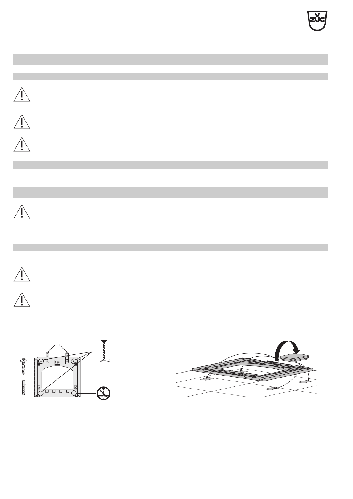
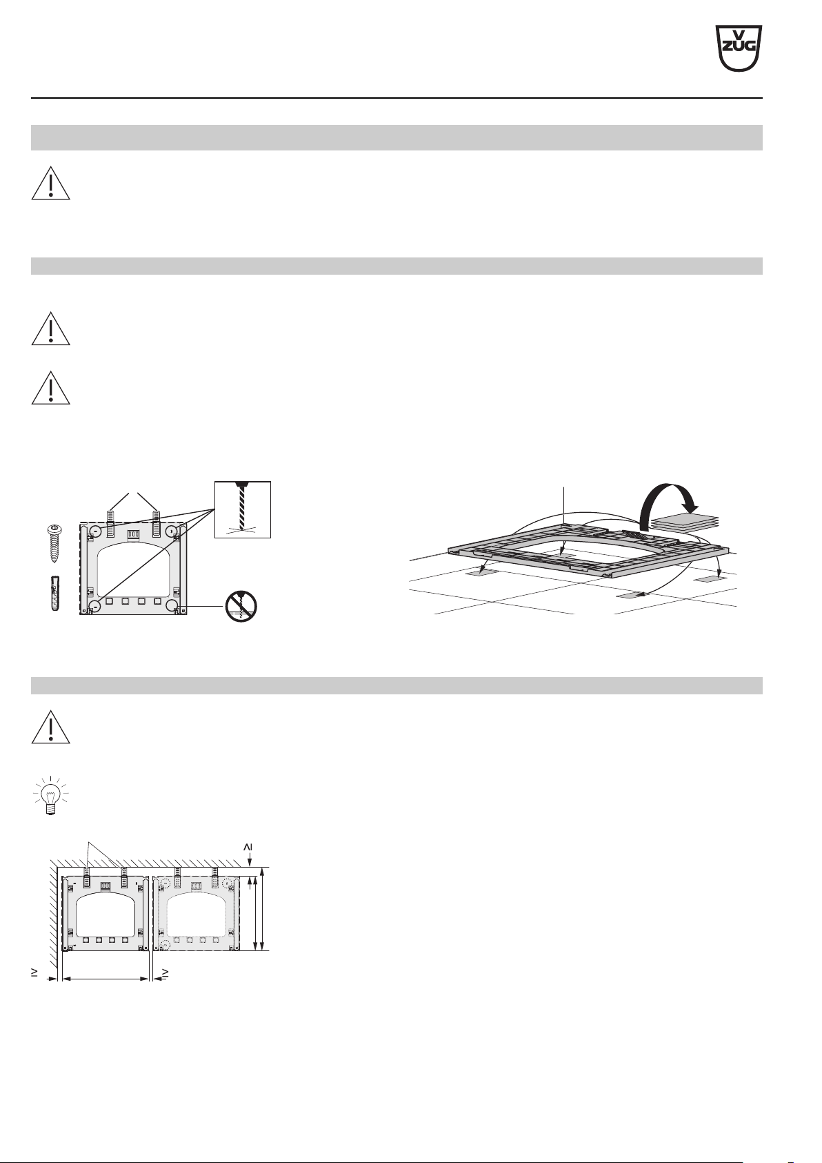
Installation plate (W40653)
General condition
The installation plate is used as an installation aid and its use is obligatory. It can be fixed to the floor with double-sided ad-
hesive tape or it can be screwed to the floor.
Failure to observe said precautions can result in injury or in damage to the appliance or fittings!
If a room has underfloor heating the installation plate may only be adhered (fastening material is included in the scope of
delivery).
Failure to observe said precautions can result in injury or in damage to the appliance or fittings!
Without underfloor heating With underfloor heating
3×
ø6
D
► Fold out spacers D. ► Fold out spacers D.
► Screw installation plate into place. ► Adhere installation plate into place.
V-ZUG Ltd
V-ZUG Ltd, Industriestrasse 66, CH-6302 Zug
[email protected], www.vzug.com
Planning aid
International collection
Laundry room appliances
J001062-R16
30.04.19
15
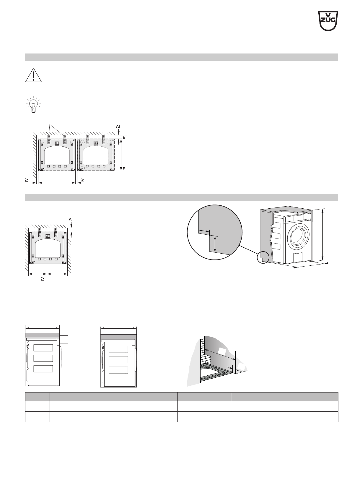
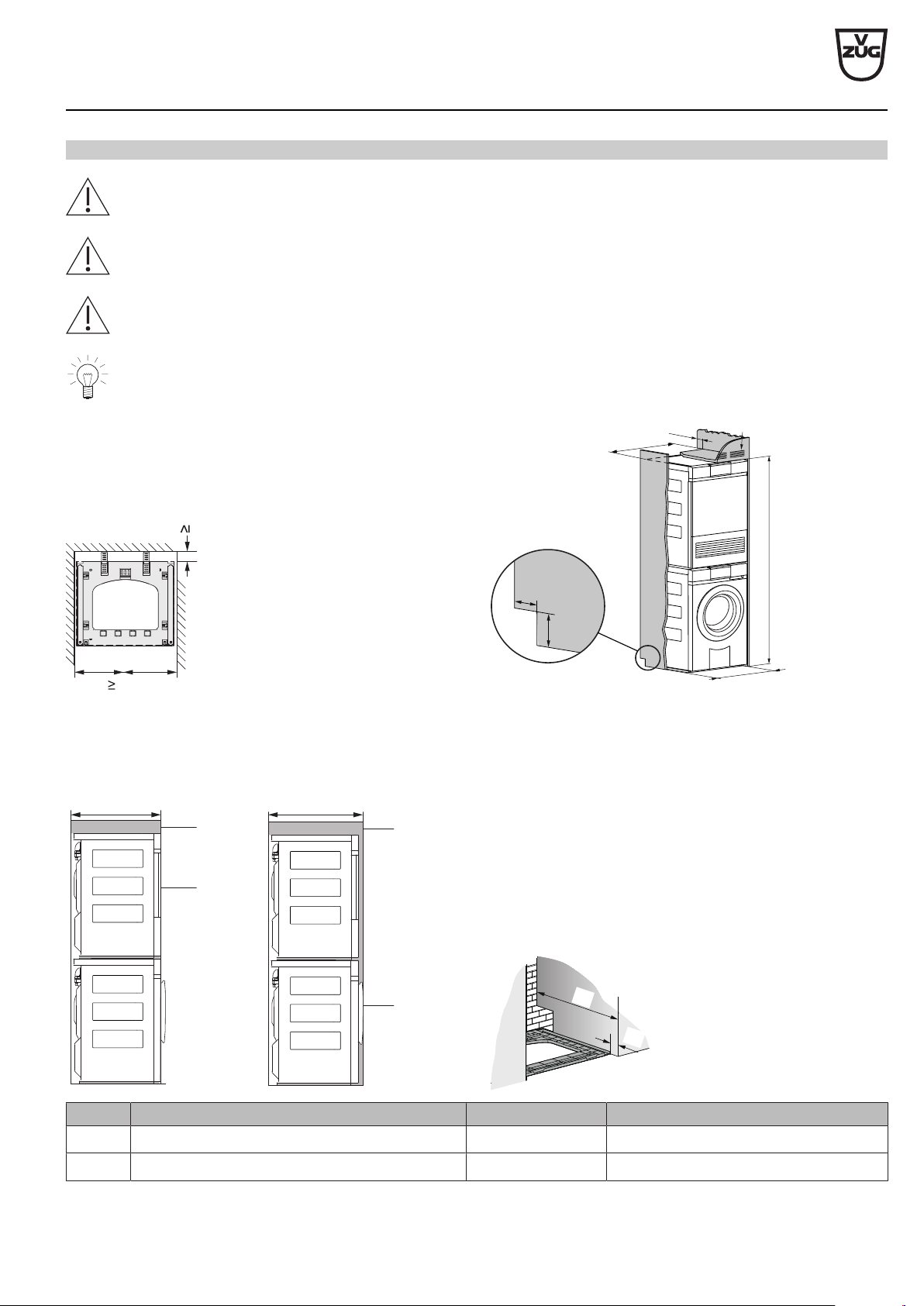
Free-standing position
If a tumble dryer and a washing machine are positioned side by side, keep a distance of min. 5mm between the installation
plates and to the walls at the side and min. 45mm to the back wall. The installation plates for the washing machine and
tumble dryer are the same.
Dimensions 45 and 555 only apply if no plumbing fittings are to be installed behind the appliance.
45
5
595
510
5
555
D
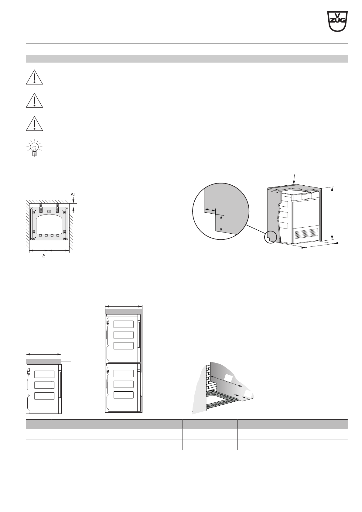
Positioning in a niche
≥860
≥
605
≥1
00
≥1
00
605
45
► Centre the installation plate in the niche.
► Niche width: ≥605mm
► Distance to the back wall: ≥45mm
► Cut-out for connections (left or right): ≥100×100mm
► Niche height: ≥860mm
Variant 1 Variant 2
A
C
B
A
E
B
1
00
1
00
A
D
Variant Positioning Niche depth A Installation offset for installation plate D
1 Niche front B and appliance front C are flush ≥605 mm 50 mm
2 Niche front B appliance door E are flush ≥645 mm 83 mm
V-ZUG Ltd
V-ZUG Ltd, Industriestrasse 66, CH-6302 Zug
[email protected], www.vzug.com
Planning aid
International collection
Laundry room appliances
J001062-R16
30.04.19
16
5
Tumble dryers
The following tumble dryers are condenser dryers with a heat pump. The process circuit of the heat pump dryer is completely closed.
The hot humid air is cooled and condensed in the 1st heat exchanger and then re-heated in the 2nd heat exchanger.
The heat pump dryer has roughly half the energy consumption of conventional tumble dryers, a higher air flow rate and a lower dry-
ing temperature. This results in particularly gentle drying, especially suitable for heat-sensitive textiles such as synthetics and blen-
ded fabric. The heat pump dryers satisfy the stringent requirements of the Minergy (minimum energy) standard.
5.1
Electrical connection data
Appliance Country group * Mains connection Rated load Fuse Mains cable
AdoraDry V6000 A, D, E 220–240V~ 50Hz 1050W 10A with plug 2.3 m
C, F 220–240V~ 50Hz 1050W 10A with plug 2.2 m
AdoraDry V2000 A, D, E 220–240V~ 50Hz 750W 10A with plug 2.3 m
C 220–240V~ 50Hz 750W 10A with plug 2.2 m
* Key (see page 2)
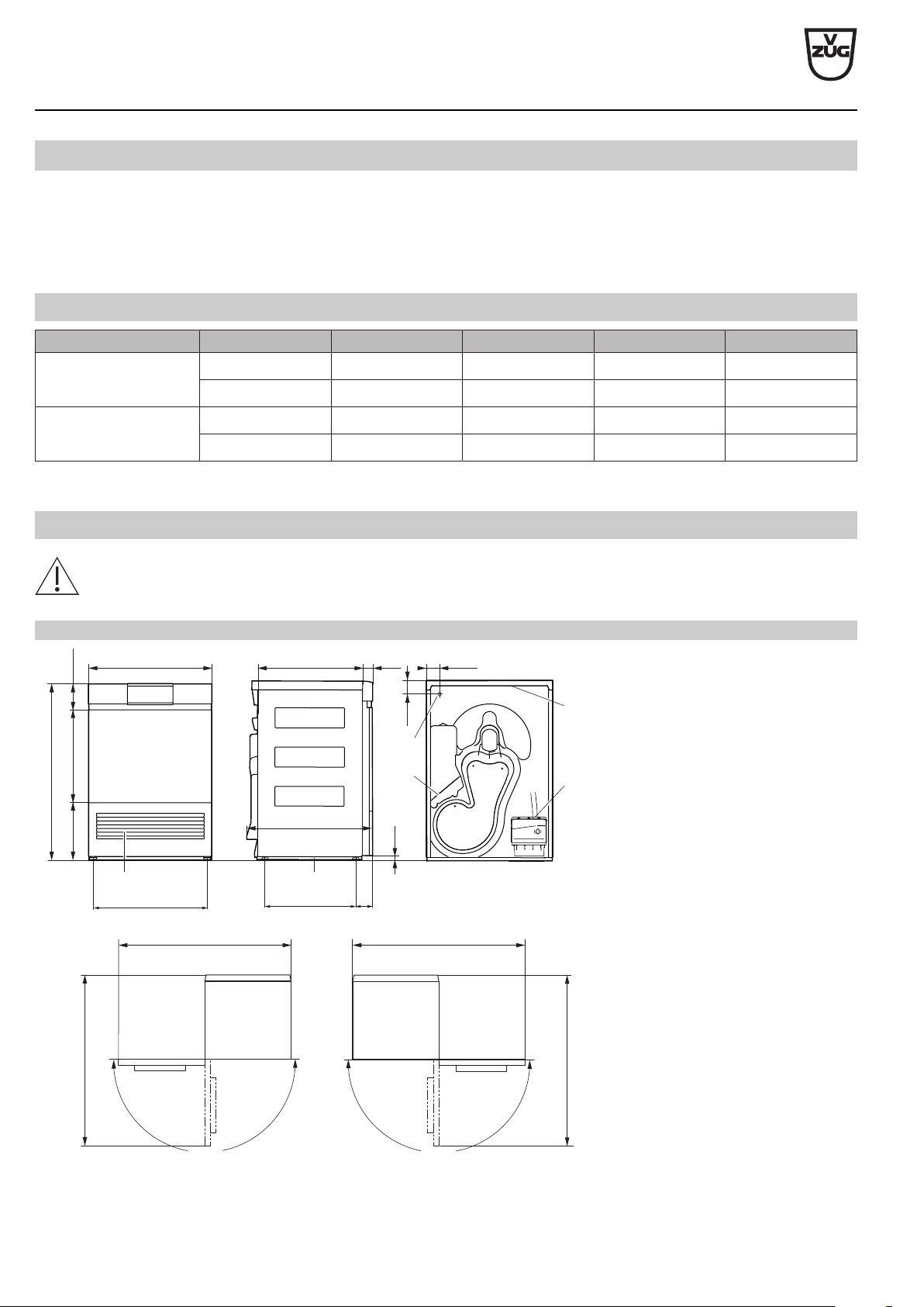
5.2
Dimensions
The stated dimensions do not include distances from walls. To prevent disturbing noise and vibration the appliances must
not come into contact with the surrounding walls of their installation location.
AdoraDry V2000, V6000
1160
1200*
180°
180°
1200*
1160
595
70
15
600
500 50
57.5
3
6
1
5
(126)444280
850
2
4
550
458
71
Left-hand opening Right-hand opening
1 Cooling air inlet
2 Cooling air outlet
3 Installation plate
4 Tower panel
5 Electrical connection cable outlet,
length: 1.8 m, with plug
6 Condensate drain
drainage connection: ø10.5 mm
pumping height for drain pump: 1.2 m
condensate drain kit,
length:2m
* Clearance space across the whole
width of the front
V-ZUG Ltd
V-ZUG Ltd, Industriestrasse 66, CH-6302 Zug
[email protected], www.vzug.com
Planning aid
International collection
Laundry room appliances
J001062-R16
30.04.19
17
5.3
Installation
General condition
To prevent an impermissible rise in temperature and humidity, the room must be min. 20 m
3
in size and sufficiently large in-
let and outlet openings to an adjacent room or to the outside must be available (open windows, ventilation grilles or slots in
the door, ventilation systems). On the other hand there is the possibility of using the waste heat.
Normal bathroom extractor fans are not adequate for optimal room ventilation. They switch off with the light after a preset
after-running time.
Through the heat recovery of the heat pump dryer, heat dissipation is greatly reduced, resulting in the imposition of far fewer de-
mands on the installation room. Heat pump dryers affect their environment like a heater blower with a heat output of approx. 700 W.
All Adora appliances must be mounted on the installation plate supplied. Only in this case is problem-free operation guaran-
teed. The appliances can be levelled by means of adjustable feet.
The room must be kept free of dust and fluff.
Room temperature
Permissible room temperature: 5 °C to 35 °C
The room temperature must be kept between the range of 15–25°C to ensure the economic running of the appliance. A
room temperature of over 35 °C is critical and extends the duration of the individual programmes. High temperatures can
also result in error messages and impair the service life of the appliance.
Ventilation
As a general rule, rooms containing heat pump dryers should be ventilated as these produce a small amount of moisture. For each
heat pump dryer, the passage of exhaust and intake air must be guaranteed. EXHAUST AIR requires INTAKE AIR. At least the same
amount of air must be supplied to as is being extracted from the room.
Ventilation concepts
Installation room volume <20 m
3
:
► There must be air inlet and outlet openings (open window, ventilation grille or slits in the
door, ventilation system) to the adjacent room or to the outside.
► Operation is trouble-free with an air circulation rate from 15 m
3
/h.
Installation room volume ≥20 m
3
, room kept closed:
► Condensation may form on thermal bridges!
► The room must be aired (by opening the door to or a window in the room) between con-
secutive drying programmes!
V-ZUG Ltd
V-ZUG Ltd, Industriestrasse 66, CH-6302 Zug
[email protected], www.vzug.com
Planning aid
International collection
Laundry room appliances
J001062-R16
30.04.19
18
5.4
Positioning
To prevent disturbing noise and vibration the appliance must not come into contact with the surrounding walls of its installa-
tion location. It is imperative to comply with the supplied installation instructions for positioning the appliance.
► The appliance must stand level and stable. Check with a spirit level.
► The appliance must not wobble in case of a crosswise load.
Installation plate (W40653)
General condition
The installation plate is used as an installation aid and its use is obligatory. It can be fixed to the floor with double-sided ad-
hesive tape or it can be screwed to the floor.
Failure to observe said precautions can result in injury or in damage to the appliance or fittings!
If a room has underfloor heating the installation plate may only be adhered (fastening material is included in the scope of
delivery).
Failure to observe said precautions can result in injury or in damage to the appliance or fittings!
Without underfloor heating With underfloor heating
3×
ø6
D
► Fold out spacers D. ► Fold out spacers D.
► Screw installation plate into place. ► Adhere installation plate into place.
Free-standing position
If a tumble dryer and a washing machine are positioned side by side, keep a distance of min. 5mm between the installation
plates and to the walls at the side and min. 45mm to the back wall. The installation plates for the washing machine and
tumble dryer are the same.
Dimensions 45 and 555 only apply if no plumbing fittings are to be installed behind the appliance.
45
5
595
510
5
555
D
V-ZUG Ltd
V-ZUG Ltd, Industriestrasse 66, CH-6302 Zug
[email protected], www.vzug.com
Planning aid
International collection
Laundry room appliances
J001062-R16
30.04.19
19
Positioning in a niche
If a tumble dryer is installed in a niche, a 130° door stop must be provided (article no. W54086).
If the niche is fitted with a door, it must be ensured that the door is left open for the duration of the process. The niche door
and the appliance door must be hinged on the same side.
The condensed water hose must not be crushed between the rear of the appliance and the building wall.
The heat given off from the rear of the appliance must be conducted out of the niche. By means of 2 ventilation grilles
P33002 (see page 31) or a ventilation cross-section of min. 400 cm
2
in the niche cover ensure there is a supply of fresh air
via the connection opening.
≥860
≥
605
400 cm²
≥100
≥100
605
45
► Centre the installation plate in the niche.
► Niche width: ≥605mm
► Distance to the back wall: ≥45mm
► Cut-out for connections (left or right): ≥100×100mm
► Niche height: ≥860mm
► Ventilation cross-section: ≥400cm
2
Variant 1 Variant 2
A
E
B
A
C
B
1
00
1
00
A
D
Variant Positioning Niche depth A Installation offset for installation plate D
1 Niche front B and tumble dryer front C are flush ≥605 mm 50 mm
2 Niche front B and washing machine door E are flush ≥645 mm 83 mm
V-ZUG Ltd
V-ZUG Ltd, Industriestrasse 66, CH-6302 Zug
[email protected], www.vzug.com
Planning aid
International collection
Laundry room appliances
J001062-R16
30.04.19
20
6
Washer-dryer towers
For safety reasons, tumble dryers standing upon washing machines are never to be mounted and operated without the as-
sociated installation plate.
Disconnection points must be provided for the water supply and electrical connection, which must be capable of being actu-
ated without moving the appliances.
6.1
Installation
Washing machines
Install the washing machine as per the section on Installation (see page 14).
Tumble dryers
Install the tumble dryer as per the section on Installation (see page 17).
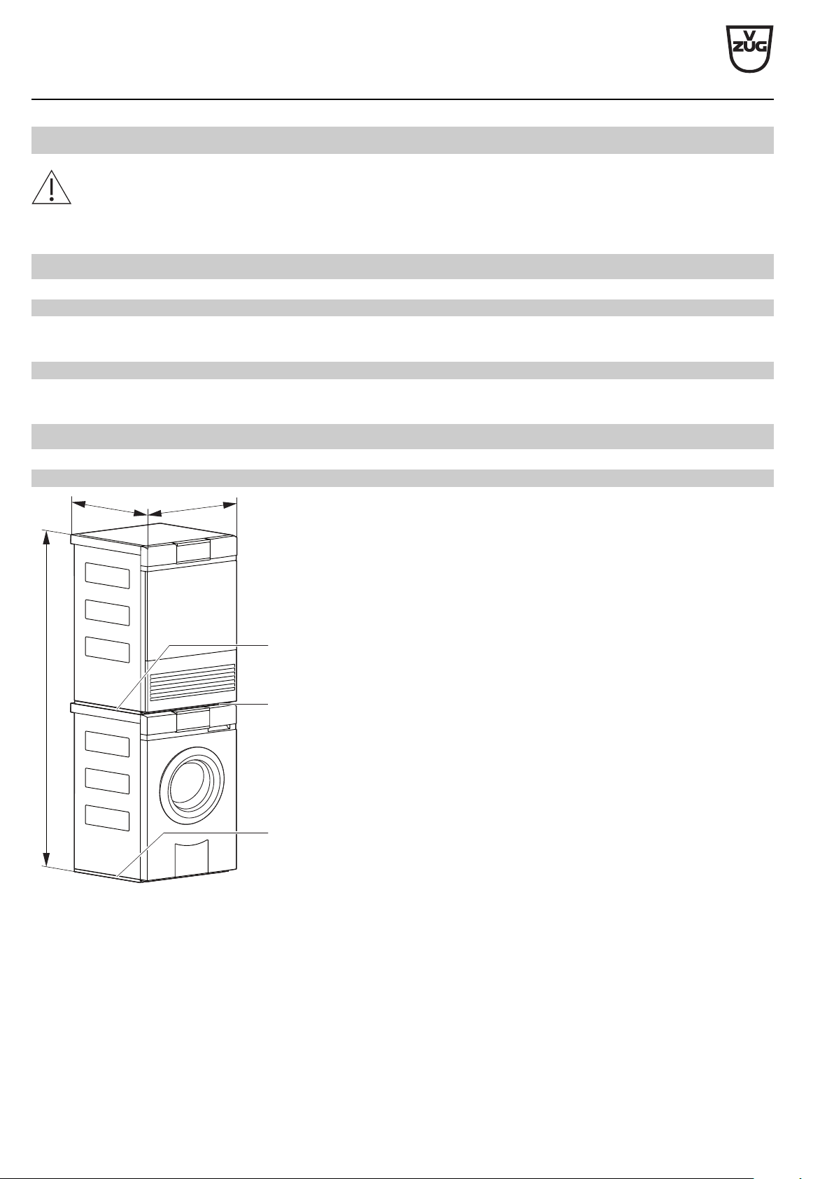
6.2
Positioning
Free-standing position
1700
595
577
1
1
2
1 Installation plate
2 Tower panel (when delivered, attached to the cover plate at the back of the
tumble dryer)
V-ZUG Ltd
V-ZUG Ltd, Industriestrasse 66, CH-6302 Zug
[email protected], www.vzug.com
Planning aid
International collection
Laundry room appliances
J001062-R16
30.04.19
21
Positioning in a niche
If a tumble dryer is installed in a niche, a 130° door stop must be provided (article no. W54086).
If the niche is fitted with a door, it must be ensured that the door is left open for the duration of the process. The niche door
and the appliance door must be hinged on the same side.
The condensed water hose must not be crushed between the rear of the appliance and the building wall.
The heat given off from the rear of the appliance must be conducted out of the niche. By means of 2 ventilation grilles
P33002 or a ventilation cross-section of min. 400 cm
2
in the niche cover ensure there is a supply of fresh air via the connec-
tion opening.
400 cm²
≥1710
≥50
≥605
≥
605
≥100
≥100
605
50
► Centre the installation plate in the niche.
► Niche width: ≥605mm
► Distance to the back wall: ≥50mm
► Cut-out for connections (left or right): ≥100×100mm
► Niche height: ≥1710mm
► Ventilation cross-section: ≥400cm
2
Variant 1 Variant 2
A
C
B
A
E
B
1
00
1
00
A
D
Variant Positioning Niche depth A Installation offset for installation plate D
1 Niche front B and tumble dryer door C are flush ≥605 mm 50 mm
2 Niche front B and washing machine door E are flush ≥645 mm 83 mm
V-ZUG Ltd
V-ZUG Ltd, Industriestrasse 66, CH-6302 Zug
[email protected], www.vzug.com
Planning aid
International collection
Laundry room appliances
J001062-R16
30.04.19
22
7
Combined washer-dryer
7.1
Electrical connection data
Appliance Country group * Mains connection Rated load Fuse Mains cable
Adorina CS C 220–240V~ 50Hz 2200W 13A with plug
(BS 1363) 2.2 m
F 220–240V~ 50Hz 2200W 10A with plug
(CH2-16P) 2.2 m
* Key (see page 2)
7.2
Dimensions
The stated dimensions do not include distances from walls. To prevent disturbing noise and vibration the appliances must
not come into contact with the surrounding walls of their installation location.
Adorina CS (11018)
1
23
822 –834
169–181
596
552
552*
433
461
28
60
26
92°
1 Drainage hose connection with elbow,
length 2.2m, pumping height for drain
pump 900mm
2 Cold water connection, Aquastop
2.2mG¾“ included in the scope of deliv-
ery
3 Electrical connection cable outlet,
length: 2.2m, with plug
* For measurement with Aquastop, add an-
other 14mm
V-ZUG Ltd
V-ZUG Ltd, Industriestrasse 66, CH-6302 Zug
[email protected], www.vzug.com
Planning aid
International collection
Laundry room appliances
J001062-R16
30.04.19
23
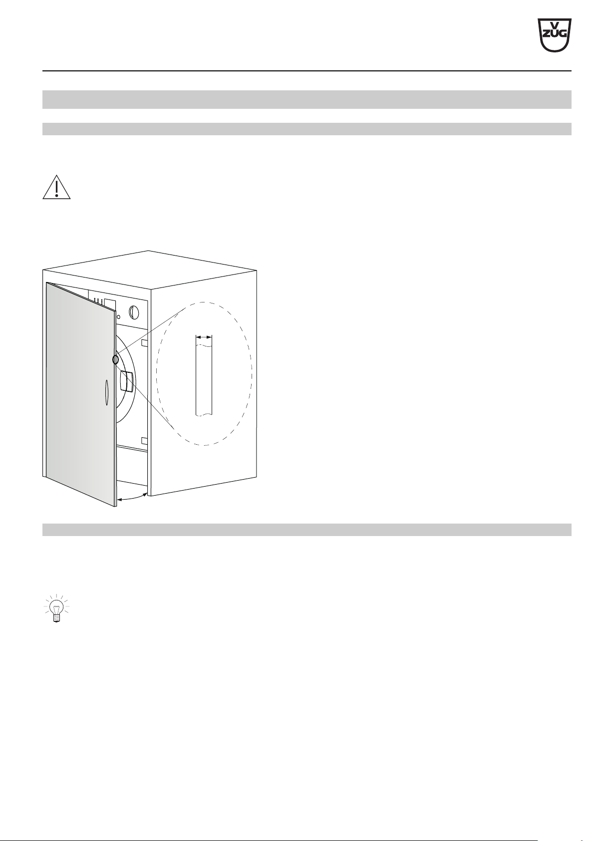
7.3
Installation
General condition
The Adorina appliances have 4 adjustable feet to correct for uneven or sloped floors. The height adjustment allows for a 6–15 mm
gap from the bottom side of appliance to the floor.
The «Adorina combined washer-dryer» may only be used with a decor panel.
Hinges, magnetic locks and and push-pull locks for mounting the decor panel are included in the scope of delivery (see page 31).
The decor panel can be mounted to the left or right (see document 1017089).
A
B
A Thickness of decor panel 16–21mm
B Opening angle: ≥110mm
Room climate and ventilation
Room temperature
Permissible room temperature:
Tower with tumble dryer: 5 °C to 35 °C
The room temperature should be kept as low as possible to ensure the economic running of the appliance. A room temper-
ature of over 35°C is critical and extends the duration of the individual programmes. High temperatures can also result in
error messages and impair the service life of the appliance.
Ventilation
For further details, refer to the section on room climate and ventilation (see page 17). See the installation instructions for further in-
structions.
V-ZUG Ltd
V-ZUG Ltd, Industriestrasse 66, CH-6302 Zug
[email protected], www.vzug.com
Planning aid
International collection
Laundry room appliances
J001062-R16
30.04.19
24
7.4
Positioning
► The appliance must stand level and stable. Check with a spirit level.
► The appliance must not wobble in case of a crosswise load.
The floor surface must be clean, dry, free of floor wax residue and other lubricating coatings so that the appliance does not slide
away! Do not use pieces of wood, cardboard or the like to compensate for any small irregularities in the floor surface (a floor attach-
ment plate set no. 81131132 may be used to secure the appliance). If, for reasons of space, it is not possible to avoid installing the
appliance directly next to a gas or coal-fired appliance: install a thermal insulation panel between the cooker and the appliance
(85×57cm) which must have an aluminium film on the side against the cooker.
Positioning in a niche
The Adorina appliances have 4 adjustable feet to correct for uneven or sloped floors. The height adjustment allows for a 6–15 mm
gap from the bottom side of appliance to the floor.
Niche
Decor panel
A
A
≥
600
1
B
► Cut-out for connections 1 (left or right):
≥50 × 100mm or
≥80 × 80mm
► Niche depth A: ≥584mm
► Niche height B: ≥825mm
► Appliance decor panel or appliance panel flush with neigh-
bouring appliances/panels
V-ZUG Ltd
V-ZUG Ltd, Industriestrasse 66, CH-6302 Zug
[email protected], www.vzug.com
Planning aid
International collection
Laundry room appliances
J001062-R16
30.04.19
25
8
Textile care system
8.1
Electrical connection data
Appliance Country group * Mains connection Rated load Fuse Mains cable
RefreshButler V6000 A, B, C, E 230V~ 50Hz 1200W 10A with plug 2.2 m
D, F 220–240V~ 50Hz 1200W 10A with plug 2.2 m
* Key (see page 2)
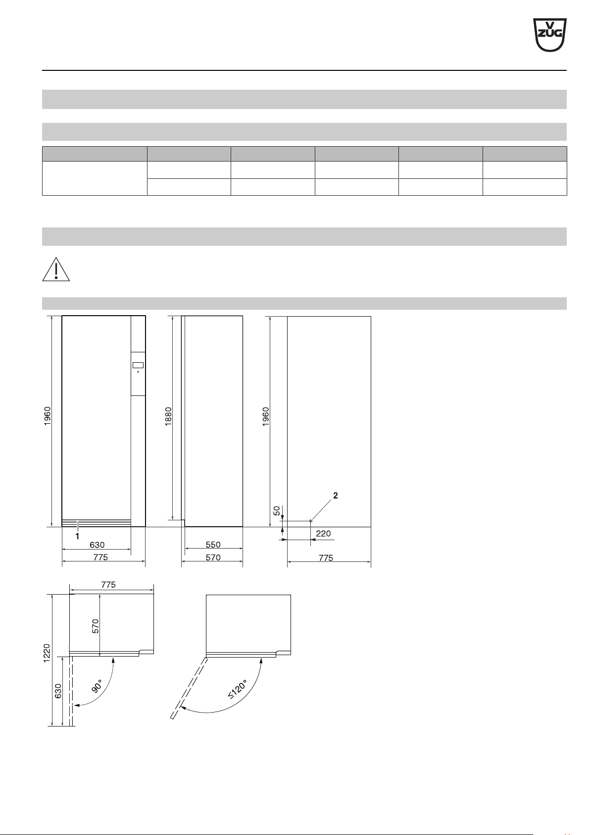
8.2
Dimensions
The stated dimensions do not include distances from walls. To prevent disturbing noise and vibration the appliances must
not come into contact with the surrounding walls of their installation location.
RefreshButler V6000 (14003)
1 Cooling air inlet
2 Electrical connection cable outlet,
length: 2.2m, with plug
V-ZUG Ltd
V-ZUG Ltd, Industriestrasse 66, CH-6302 Zug
[email protected], www.vzug.com
Planning aid
International collection
Laundry room appliances
J001062-R16
30.04.19
26
8.3
Installation
General condition
To prevent an impermissible rise in temperature and humidity, the room must be min. 20 m
3
in size and sufficiently large in-
let and outlet openings to an adjacent room or to the outside must be available (open windows, ventilation grilles or slots in
the door, ventilation systems). On the other hand there is the possibility of using the waste heat.
Normal bathroom extractor fans are not adequate for optimal room ventilation. They switch off with the light after a preset
after-running time.
Through the heat recovery of the heat pump dryer, heat dissipation is greatly reduced, resulting in the imposition of far fewer de-
mands on the installation room. Heat pump dryers affect their environment like a heater blower with a heat output of approx. 700 W.
The appliance can be levelled by means of adjustable feet. The room must be kept free of dust and fluff.
Ventilation
As a general rule, rooms containing a textile care appliance must be ventilated as these produce some humidity. For each heat pump
dryer, the passage of exhaust and intake air must be guaranteed. EXHAUST AIR requires INTAKE AIR. At least the same amount
of air must be supplied to as is being extracted from the room. If the room is kept closed, the installation room volume must be min.
20 m
3
.
8.4
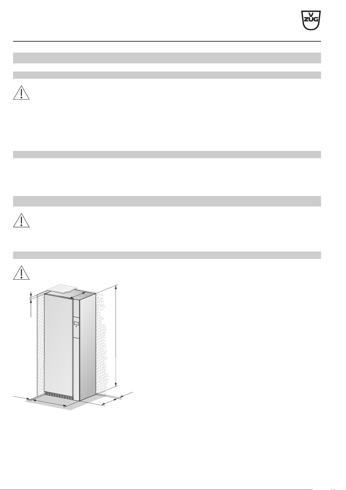
Positioning
To prevent disturbing noise and vibration the appliance must not come into contact with the surrounding walls of its installa-
tion location. It is imperative to comply with the supplied installation instructions for positioning the appliance.
► The appliance must stand level and stable. Check with a spirit level.
► The appliance must not wobble in case of a crosswise load.
Free-standing position
When positioning a RefreshButler so that it is free-standing, a distance of min. 3mm must be kept to the walls to the left
and right.
≥3
775
550
≥1
1
≥50
1
960
570
V-ZUG Ltd
V-ZUG Ltd, Industriestrasse 66, CH-6302 Zug
[email protected], www.vzug.com
Planning aid
International collection
Laundry room appliances
J001062-R16
30.04.19
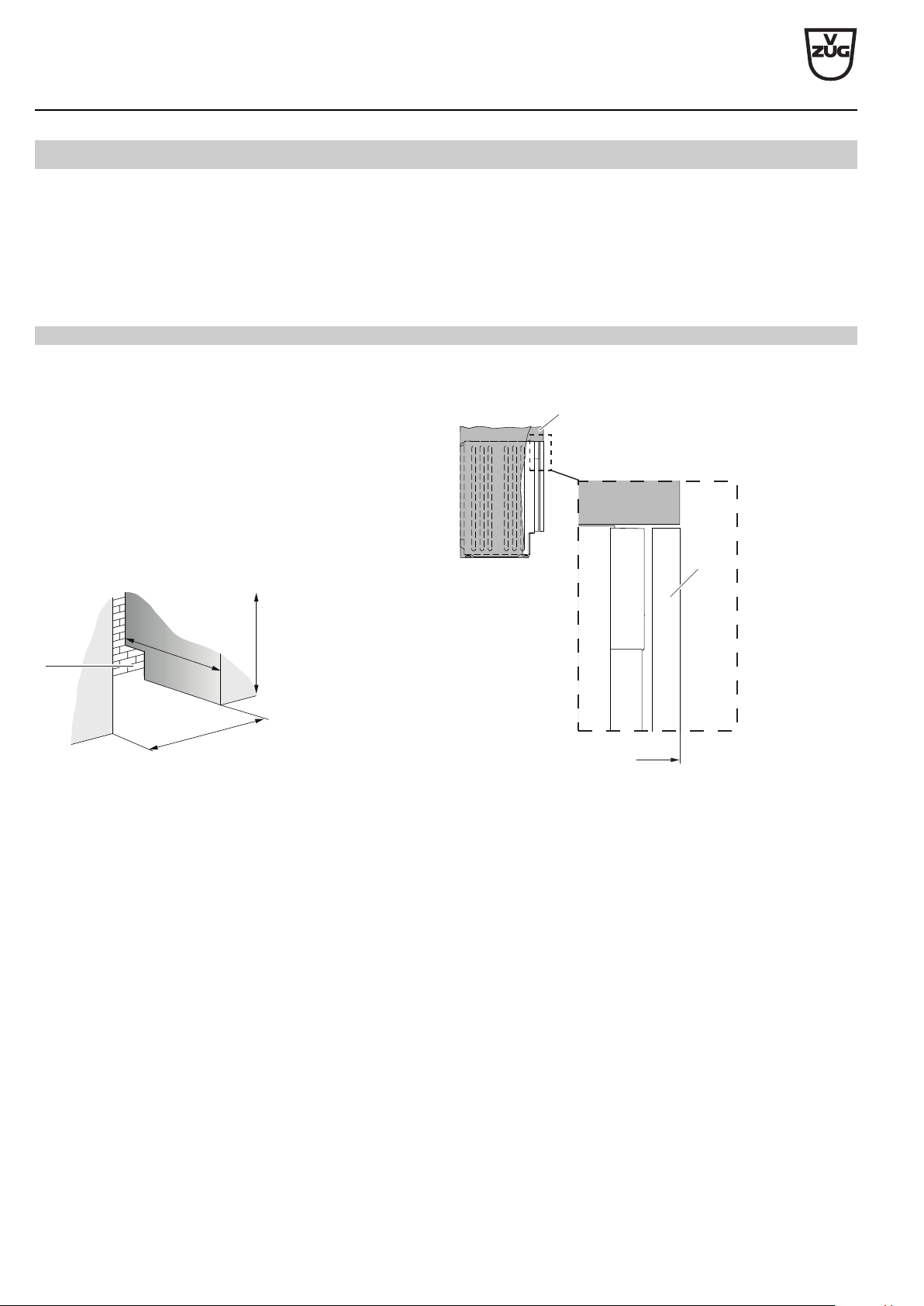
27
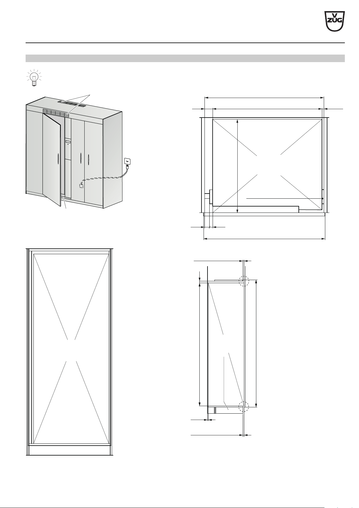
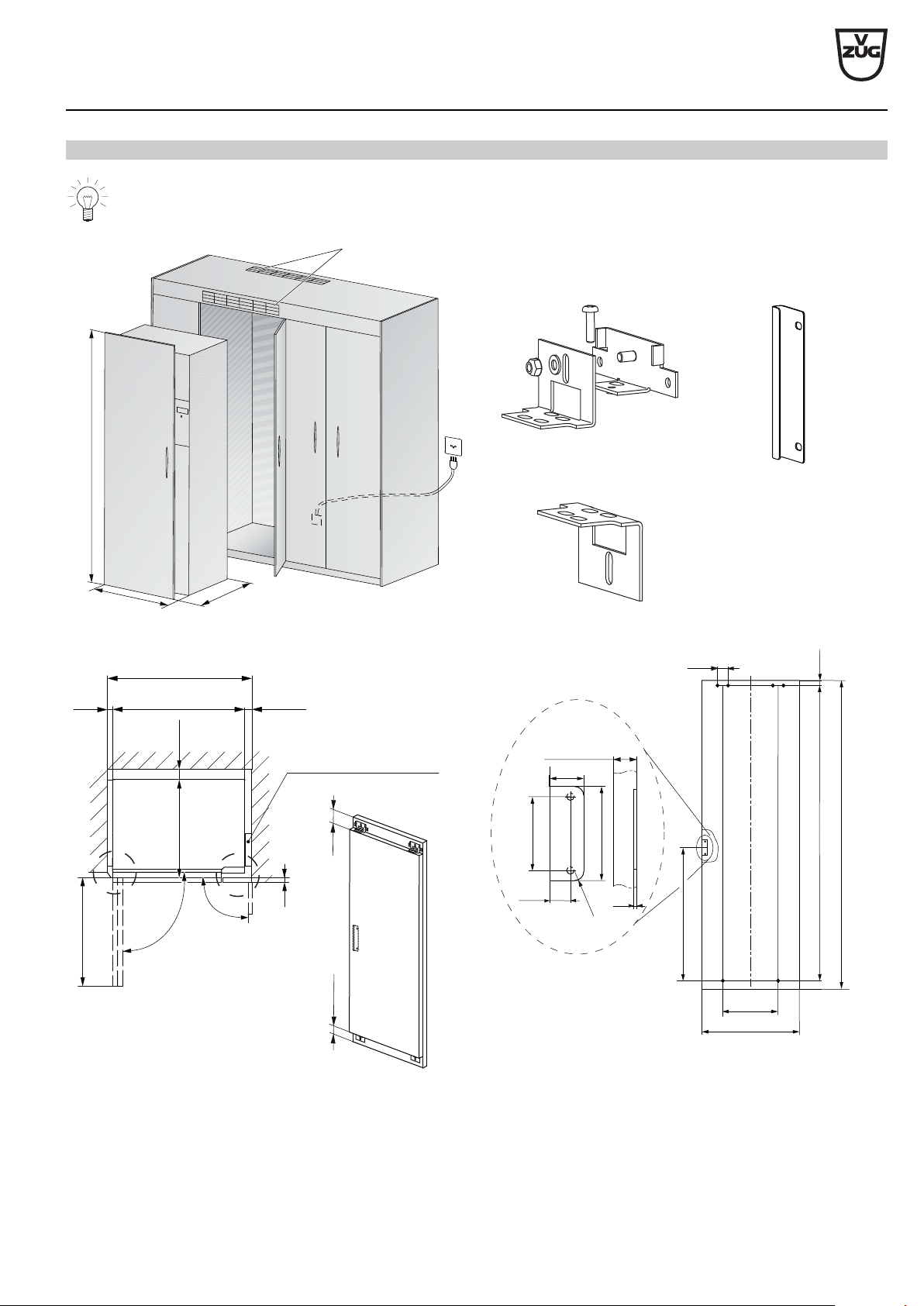
Positioning in a niche (without decor panel)
The door extends across entire width of opening. There is no connection to the RefreshButler door.
A = ≥200 cm²
B
19
852
30
49 775
837
12+1
570
RefreshButler
Mount filler strip
after installing appliance
A Ventilation slit on the top at the back or above the cabinet
door
B Load-bearing capacity of cabinet floor: min.170kg
Cabinet door with tape
affixed on side
RefreshButler
Floor 25 mm back
for air circulation
Base reinforcement for appliance
≥11
2028
1960
30
Floor 25 mm back
for air circulation
Ceiling 25 mm back
for air circulation
Base reinforcement
for appliance
Detail Z
Detail Y
RefreshButler
V-ZUG Ltd
V-ZUG Ltd, Industriestrasse 66, CH-6302 Zug
[email protected], www.vzug.com
Planning aid
International collection
Laundry room appliances
J001062-R16
30.04.19
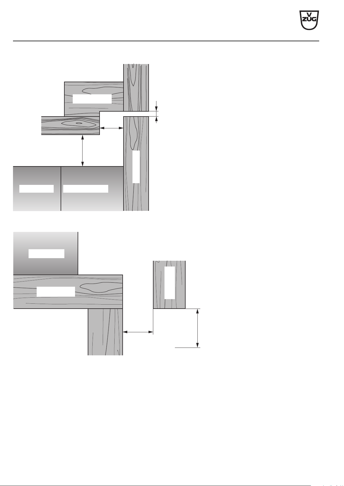
28
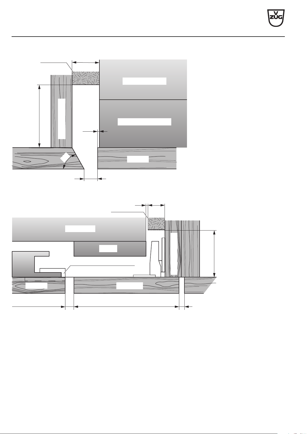
Detail Y
4
30
25
RefreshButler door
RefreshButler
Cabinet ceiling
Cabinet door
Detail Z
RefreshButler
25
≥25
Minimum distance
to floor
Cabinet base
Cabinet door
V-ZUG Ltd
V-ZUG Ltd, Industriestrasse 66, CH-6302 Zug
[email protected], www.vzug.com
Planning aid
International collection
Laundry room appliances
J001062-R16
30.04.19
29
Positioning in a niche (with decor panel)
The decor panel is fastened to the RefreshButler door.
7
7
5
2028
5
7
0
+
C
B
A = ≥200 cm²
Angle bracket *
Upper
angle bracket
Middle
angle bracket
Lower
angle bracket
69
(32)
1922
2028 (Decor panel height)
360
643
(Decor panel
width)
866
102
37
22.5
R10
80
10–19
(Decor panel
thickness)
4
E
49
≥40
(775)19 15 + 1
810
Monut right filler strip
after installing appliance
C
643
90°
570
Detail
W
Detail
X
≥ 11
D
90°
A Ventilation slit on the top at the back or above the cabinet
door
D RefreshButler door with decor panel and 5 angle brackets*
Maximum permissible weight of decor panel: 35kg
B Load-bearing capacity of cabinet floor:
min.170kg+weight of decor panel
C Thickness of decor panel E Installation drawing for decor panel
* included in the scope of delivery (see installation set
W56295)
V-ZUG Ltd
V-ZUG Ltd, Industriestrasse 66, CH-6302 Zug
[email protected], www.vzug.com
Planning aid
International collection
Laundry room appliances
J001062-R16
30.04.19
30
Detail W
RefreshButler door
RefreshButler
7
1.2
19
50
Filler strip
Decor panel
Cabinet inside panel
60°
Detail X
7643 156
Hinge
Filler strip
4
151
RefreshButler
Middle angle bracket
Display
50
Cabinet inside panel
Decor panel
Door display
V-ZUG Ltd
V-ZUG Ltd, Industriestrasse 66, CH-6302 Zug
[email protected], www.vzug.com
Planning aid
International collection
Laundry room appliances
J001062-R16
30.04.19
31
9
Accessories
You can order the appropriate accessories for your V-ZUG appliances directly from our accessories shop. Visit vzug.com for
more information.
9.1
Washing machines
Designation Article no. Model designation
4m drain hose set, can be shortened: max.permissible drain
height ≤ water outlet out of appliance ~80 cm.
W33543 AdoraWash V2000–V6000
Hose support (included in the 4m drain hose set) 80868039 AdoraWash V2000–V6000
Long hose set (3m Aquastop hose and 4m drain hose) 1012989 AdoraWash V2000–V6000
9.2
Tumble dryers
Designation Article no. Model designation
Ventilation grille P33002 AdoraDry V2000, V6000
Fixing discs (set of 2 discs) 81131132 AdoraDry V2000, V6000
Combi drainage set W55969 AdoraDry V2000, V6000
Condensate drain kit (included in the scope of delivery) W56298 AdoraDry V2000, V6000
Backflow preventer W50028 AdoraDry V2000, V6000
Drying basket set W55884 AdoraDry V2000, V6000
Tower panel (included in the scope of delivery) W55687 AdoraDry V2000, V6000
130° door stop for niche installation W54086 AdoraDry V2000, V6000
9.3
Textile care system
Designation Article no. Model designation
5 clothes hangers (included in the scope of delivery) W54789 RefreshButler V6000
1 basket (included in the scope of delivery) W56746 RefreshButler V6000
durgol swiss steamer descaler B28006 RefreshButler V6000
9.4
Combined washer-dryer
Designation Article no. Model designation
Accessories set for decor panel, cpl., left/right (included in the
scope of delivery)
1022304 Adorina CS
4m drain hose set 1034496 Adorina CS

CONTACT IN SWITZERLAND V-ZUG Ltd
Industriestrasse 66
CH-6302 Zug/Switzerland
www.vzug.com
Service & Support International
Tel. +41 58 767 67 78