Your vehicle is equipped with a key fob which supports Passive Entry, Remote Keyless Entry (RKE), Keyless Enter-N-Go (if equipped), and Remote Start (if equipped). The key fob allows you to lock or unlock the doors and tailgate from distances up to approximately 66 ft (20 m). The key fob does not need to be pointed at the vehicle to activate the system. The key fob also contains a mechanical key.
NOTE:
The key fob’s wireless signal may be blocked if the key fob is located next to a mobile phone, laptop, or other electronic device.
This may result in poor performance.
With the ignition on and the vehicle moving at 2 mph (4 km/h), all RKE commands are disabled.
Mechanical Key Release Button
Unlock Button
Remote Start Button
Panic Button
LED Indicator
Lock Button
To Lock/Unlock The Doors And Tailgate
Push and release the unlock button on the key fob once to unlock the driver’s door, or twice to unlock all the doors. To lock all the doors, push the lock button once.
When the doors are unlocked, the turn signals will flash and the illuminated entry system will be activated. When the doors are locked, the turn signals will flash and the horn will chirp.
NOTE:
All doors can be programmed to unlock on the first push of the unlock button through Uconnect Settings page 235.
The mechanical flip key can be used to lock or unlock the doors, tailgate, glove compart ment, storage compartments (if equipped), and rear seatbacks.
Using The Panic Alarm
To turn the Panic Alarm feature on or off, push the panic button on the key fob. When the Panic
Alarm is activated, the turn signals will flash, the horn will pulse on and off, and the interior lights will turn on.
The Panic Alarm will stay on for three minutes unless you turn it off by either pushing the panic button a second time or drive the vehicle at a speed of 2 mph (4 km/h) or greater.
NOTE:
The interior lights will turn off if you place the ignition in the ACC or ON/RUN position while the Panic Alarm is activated. However, the exterior lights and horn will remain on.
You may need to be less than 35 ft (11 m) from the vehicle when using the key fob to turn off the Panic Alarm due to the radio frequency noises emitted by the system.
Replacing The Battery In The Key Fob
The recommended replacement battery is CR2450.
NOTE:
Customers are recommended to use a battery obtained from Mopar®. Aftermarket coin battery dimensions may not meet the original OEM coin battery dimensions.
Perchlorate Material — special handling may apply. See www.dtsc.ca.gov/hazardouswaste/perchlorate for further information.
Do not touch the battery terminals that are on the back housing or the printed circuit board.
When a key fob battery is low, a warning will be indicated on the vehicle’s instrument cluster, and the fob LED will no longer illuminate with a button push.
Remove the back cover of the key fob by inserting a flat-blade screw driver into the slot on the bottom of the fob. Apply light pressure until the cover unsnaps being careful not to damage the seal. Proceed counter-clockwise (in the order shown below) to loosen the remaining snaps until the battery cover can be removed.
Remove the depleted battery by inserting a small flat-blade screwdriver into the battery removal slot and sliding the battery forward and upward being careful not to damage the electronic board underneath.
Install the new battery into the key fob, making sure the positive (+) side is facing up. Slide the battery until it is seated securely below the tabs.
Reassemble the back cover making sure it is properly aligned before snapping it back in place.
Programming And Requesting Additional Key Fobs
Programming the key fob may be performed by an authorized dealer.
NOTE:
Once a key fob is programmed to a vehicle, it cannot be re-purposed and reprogrammed to another vehicle.
Only key fobs that are programmed to the vehicle electronics can be used to start and operate the vehicle. Once a key fob is programmed to a vehicle, it cannot be programmed to any other vehicle.
WARNING!
Always remove the key fobs from the vehicle and lock all doors when leaving the vehicle unattended.
For vehicles equipped with Keyless Enter-N-Go Ignition, always remember to place the ignition in the OFF position.
Duplication of key fobs may be performed at an authorized dealer. This procedure consists of programming a blank key fob to the vehicle electronics. A blank key fob is one that has never been programmed.
NOTE:
When having the Sentry Key Immobilizer system serviced, bring all vehicle keys with you to an authorized dealer page 500.
SENTRY KEY
The Sentry Key Immobilizer system prevents unauthorized vehicle operation by disabling the engine. The system does not need to be armed or activated. Operation is automatic, regardless of whether the vehicle is locked or unlocked.
The system uses a key fob, keyless push button ignition and a Radio Frequency (RF) receiver to prevent unauthorized vehicle operation. Therefore, only key fobs that are programmed to the vehicle can be used to start and operate the vehicle. The system cannot reprogram a key fob obtained from another vehicle.
After placing the ignition switch in the ON/RUN position, the Vehicle Security Light will turn on for three seconds for a bulb check. If the light remains on after the bulb check, it indicates that there is a problem with the electronics. In addition, if the light begins to flash after the bulb check, it indicates that someone attempted to start the engine with an invalid key fob. In the event that a valid key fob is used to start the engine but there is an issue with the vehicle electronics, the engine will start and shut off after two seconds.
If the Vehicle Security Light turns on during normal vehicle operation (vehicle running for longer than ten seconds), it indicates that there is a fault in the electronics. Should this occur, have the vehicle serviced as soon as possible by an authorized dealer.
All of the key fobs provided with your new vehicle have been programmed to the vehicle electronics → page 500.
IGNITION SWITCH
Keyless Enter-N-Go Ignition
This feature allows the driver to operate the ignition switch with the push of a START/STOP ignition button as long as the key fob is in the passenger compartment.
The START/STOP ignition button has several operating modes that are labeled and will illuminate when in position. These modes are OFF, ACC, RUN, and START.
The push button ignition can be placed in the following modes:
OFF
The engine is stopped.
Some electrical devices (e.g. automatic locking, alarm, etc.) are available.
ACC
Engine is not started.
Some electrical devices are available.
RUN
Driving position.
All electrical devices are available.
START
The engine will start.
NOTE:
In case the ignition switch does not change with the push of the START/STOP ignition button, the key fob may have a low or depleted battery. In this situation, a backup method can be used to operate the ignition switch. Put the nose side of the key fob (side with the mechanical flip key) against the START/STOP ignition button and push to operate the ignition switch.
NOTE: When opening the driver's door with the ignition in ON/RUN (engine not running), a chime will sound to remind you to place the ignition in the OFF position. In addition to the chime, the message will display “Ignition Or Accessory On” in the cluster.
DOORS
Manual Door Locks
All doors are equipped with an interior rocker-type door lock lever. To lock a door when leaving your vehicle, push the rocker lever forward to the lock position and close the door. To unlock the door, push the rocker lever rearward.
NOTE:
The mechanical flip key can be used to lock or unlock the door cylinders, tailgate, glove compartment, and storage compartments (if equipped).
WARNING!
For personal security reasons and safety in a collision, lock the vehicle doors when you drive, as well as when you park and exit the vehicle.
When exiting the vehicle, always place the ignition in the OFF position and remove the key from the vehicle. Unsupervised use of vehicle equipment may cause severe personal injuries and death.
Never leave children alone in a vehicle, or with access to an unlocked vehicle.
Allowing children to be in a vehicle unattended is dangerous for a number of reasons. A child or others could be seriously or fatally injured. Children should be warned not to touch the parking brake, brake pedal or the gear selector.
Do not leave the key fob in or near the vehicle or in a location accessible to children. A child could operate power windows, other controls, or move the vehicle.
Power Door Locks — If Equipped
The power door lock switch is located on each front door panel. Push the switch forward to unlock the doors, and rearward to lock the doors
Keyless Enter-N-Go — Passive Entry (If Equipped)
The Passive Entry system is a feature that allows you to lock and unlock the vehicle's door(s) and tailgate without having to push the key fob lock or unlock buttons.
NOTE:
Passive Entry may be programmed on/off through Uconnect Settings page 235.
The key fob may not be detected by the vehicle Passive Entry system if it is located next to a mobile phone, laptop, or other electronic device; these devices may interfere with the key fob's wireless signal and prevent the Passive Entry system from locking/ unlocking the vehicle.
Passive Entry Unlock initiates Headlight Illumination On Approach (low beams, license plate lamp, parking lights) for whichever time duration is set within the Uconnect Settings between 0, 30, 60 or 90 seconds. Passive Entry Unlock also initiates two flashes of the turn signal lamps.
If wearing gloves, or if it has been raining/ snowing on the Passive Entry door handle, the unlock sensitivity can be affected, resulting in a slower response time.
If the vehicle is unlocked by Passive Entry and no door is opened within 60 seconds, the vehicle will re-lock and, if equipped, will arm the Vehicle Security system.
To Unlock From The Driver Or Passenger Side
With a valid Passive Entry key fob within 5 ft (1.5 m) of the door handle, grab the handle to unlock the vehicle. Grabbing the driver's door handle will unlock the driver door automatically. Grabbing the passenger door handle will unlock all doors and the tailgate automatically.
Frequency Operated Button Integrated Key (FOBIK-Safe)
To minimize the possibility of unintentionally locking a Passive Entry key fob inside your vehicle, the Passive Entry system is equipped with an automatic door unlock feature which will function only if the ignition switch is in the OFF position.
FOBIK-Safe only executes in vehicles with Passive Entry. There are three situations that trigger a FOBIK-Safe search in any Passive Entry vehicle:
A lock request is made by a valid Passive Entry key fob while a door is open.
A lock request is made by the Passive Entry door handle while a door is open.
A lock request is made by the door panel switch while the door is open.
When any of these situations occur, after all open doors are closed, the FOBIK-Safe search will be executed. If it finds a Passive Entry key fob inside the vehicle, the vehicle will unlock and alert the customer. If Passive Entry is disabled using the Uconnect system, the key protection described in this section remains active/functional.
NOTE:
The vehicle will only unlock the doors during a FOBIK-Safe operation when a valid Passive Entry key fob is detected inside the vehicle. The vehicle will not unlock the doors when any of the following conditions are true:
A second valid Passive Entry key fob is detected outside of the vehicle (within 5 ft (1.5 m) of a Passive Entry door handle).
The doors are manually locked using the door lock knobs.
Three attempts are made to lock the doors using the door panel switch, and then the doors are closed.
To Lock The Vehicle’s Doors
With one of the vehicle's Passive Entry key fobs within 5 ft (1.5 m) of the driver or passenger front door handles, pushing the Passive Entry lock button will lock the vehicle doors.
NOTE:
When pushing the door handle lock button,
DO NOT grab the door handle. This could unlock the door(s).
AUTOMATIC CLIMATE CONTROL
DESCRIPTIONS AND FUNCTIONS
Uconnect 4 With 7-inch Display Automatic Climate Controls
Uconnect 4C/4C NAV With 8.4-inch Display Automatic Climate Controls
MAX A/C Button
Press and release the MAX A/C button on the touchscreen to change the current setting to the coldest output of air. MAX A/C sets the control for maximum cooling performance. The MAX A/C indicator illuminates when MAX A/C is on. Performing this function again will cause the MAX A/C operation to switch into manual mode and the MAX A/C indicator will turn off.
NOTE: The MAX A/C button is only available on the touchscree
A/C Button
Press and release this button on the touchscreen, or push the button on the faceplate to change the current setting. The A/C indicator illuminates when A/C is ON.
The Air Conditioning (A/C) button allows the operator to manually activate or deactivate the air conditioning system. When the air conditioning system is turned on, cool dehumidified air will flow through the outlets into the cabin.
NOTE:
If fog or mist appears on the windshield or side glass, select Defrost mode, and increase blower speed if needed.
If your air conditioning performance seems lower than expected, check the front of the A/C condenser (located in front of the radiator), for an accumulation of dirt or insects.
Clean with a gentle water spray from the front of the radiator and through the condenser.
Recirculation Button
Press and release this button on the touchscreen, or push the button on the faceplate to change the system between recirculation mode and outside air mode. The Recirculation indicator and the A/C indicator illuminate when the
Recirculation button is pressed. Recirculation can be used when outside conditions such as smoke, odors, dust, or high humidity are present. Recirculation can be used in all modes.
Recirculation may be unavailable (button on the touchscreen greyed out) if conditions exist that could create fogging on the inside of the windshield.
The A/C can be deselected manually without disturbing the mode control selection.
Continuous use of the Recirculation mode may make the inside air stuffy and window fogging may occur. Extended use of this mode is not recommended.
AUTO Button
Press and release this button on the touchscreen, or push the button on the faceplate, to change the current setting. The AUTO indicator illuminates when AUTO is on. This feature automatically controls the interior cabin temperature by adjusting distribution and blower speed. AUTO Mode is highly recommended for efficiency. Toggling this function will cause the system to switch between manual mode and automatic mode page 62.
Front Defrost
Turn the Mode control knob to Front Defrost to change the current airflow setting to Defrost mode. The Front Defrost indicator illuminates when Front Defrost is on. Air comes from the windshield and side window demist outlets.
When the defrost button is selected, the blower level may increase. Use Defrost mode with maximum temperature settings for best windshield and side window defrosting and defogging. When toggling the front defrost mode button, the Climate Control system will return to the previous setting.
Rear Defrost Button
Press and release the Rear Defrost
Control button on the touchscreen, or push and release the button on the faceplate to turn on the rear window defroster and the heated outside mirrors (if equipped). The Rear Defrost indicator illuminates when the rear window defroster is on. The rear window defroster automatically turns off after 10 minutes.
Driver And Passenger Temperature Up And Down Buttons
These buttons provide the driver and passenger with independent temperature control.
Push the red button on the faceplate or touchscreen or press and slide the temperature bar towards the red arrow button on the touchscreen for warmer temperature settings.
Push the blue button on the faceplate or touchscreen or press and slide the temperature bar towards the blue arrow button on the touchscreen for cooler temperature settings.
SYNC Button
Press the SYNC button on the touchscreen to toggle the Sync feature on/off. The SYNC indicator illuminates when SYNC is on. SYNC is used to synchronize the passenger temperature setting with the driver temperature setting.
Changing the passenger temperature setting while in SYNC will automatically exit this feature.
NOTE:
The SYNC button is only available on the touchscreen.
Blower Control
Blower Control regulates the amount of air forced through the Climate Control system. There are seven blower speeds available. Adjusting the blower will cause automatic mode to switch to manual operation.
The speeds can be selected using either the blower control knob on the faceplate or the buttons on the touchscreen.
Faceplate
The blower speed increases as you turn the blower control knob clockwise from the lowest blower setting. The blower speed decreases as you turn the blower control knob counterclockwise.
Touchscreen
Use the small blower icon to reduce the blower setting and the large blower icon to increase the blower setting. Blower can also be selected by pressing the blower bar area between the icons.
Mode Control
Turn the mode control knob or press one of the Mode buttons on the touchscreen to adjust airflow distribution. The airflow distribution mode can be adjusted so air comes from the instrument panel outlets, floor outlets, defrost outlets and demist outlets.
Panel Mode
Air comes from the outlets in the instrument panel. Each of these outlets can be individually adjusted to direct the flow of air. The air vanes of the center outlets and outboard outlets can be moved up and down or side to side to regulate airflow direction. There is a shut off wheel located below the air vanes to shut off or adjust the amount of airflow from these outlets.
Bi-Level Mode
Air comes from the instrument panel outlets and floor outlets. A slight amount of air is directed through the defrost and side window demister outlets.
NOTE:
Bi-Level mode is designed under comfort conditions to provide cooler air out of the panel outlets and warmer air from the floor outlets.
Floor Mode
Air comes from the floor outlets. A slight amount of air is directed through the defrost and side window demister outlets.
Mix Mode
Air is directed through the floor, defrost, and side window demister outlets. This setting works best in cold or snowy conditions that require extra heat to the windshield. This setting is good for maintaining comfort while reducing moisture on the windshield.
Climate Control OFF Button
Press and release this button on the touchscreen, or push and release the button on the blower knob to turn the Climate Control ON/OFF
MANUAL CLIMATE CONTROL
DESCRIPTIONS AND FUNCTIONS
Uconnect 4 With 7-inch Display Manual Climate Controls
MAX A/C Setting
Set the temperature control knob to the MAX A/C setting to change the current setting to the coldest output of air. Moving the temperature control knob away from the MAX A/C setting causes the MAX A/C operation to exit.
A/C Button
Push the A/C button to engage the Air Conditioning (A/C). The A/C indicator illuminates when A/C is on.
NOTE:
For Manual Climate Controls, if the system is in Mix, Floor or Defrost Mode, the A/C can be turned off, but the A/C system shall remain active to prevent fogging of the windows.
If fog or mist appears on the windshield or side glass, select Defrost mode, and increase blower speed if needed.
If your air conditioning performance seems lower than expected, check the front of the A/C condenser (located in front of the radiator), for an accumulation of dirt or insects. Clean with a gentle water spray from the front of the radiator and through the condenser.
Recirculation Button
Push the Recirculation button on the faceplate to change the system between recirculation mode and outside air mode. The Recirculation indicator and the A/C indicator (if equipped) illuminate when the Recirculation button is pressed. Recirculation can be used when outside conditions such as smoke, odors, dust, or high humidity are present. Recirculation can be used in all modes except for Defrost.
Recirculation may be unavailable if conditions exist that could create fogging on the inside of the windshield. The A/C can be deselected manually without disturbing the mode control selection. Continuous use of the Recirculation mode may make the inside air stuffy and window fogging may occur. Extended use of this mode is not recommended. On systems with
Manual Climate Controls, the Recirculation mode is not allowed in Defrost mode to improve window clearing operation. Recirculation is disabled automatically if this mode is selected.
Attempting to use Recirculation while in this mode causes the LED on the control button to blink and then turn off.
Front Defrost
Turn the Mode control knob to Front Defrost to change the current airflow setting to Defrost mode. The Front Defrost indicator illuminates when Front Defrost is on. Air comes from the windshield and side window demist outlets.
When the defrost button is selected, the blower level may increase. Use Defrost mode with maximum temperature settings for best windshield and side window defrosting and defogging.
When toggling the front defrost mode button, the Climate Control system will return to the previous setting.
Rear Defrost Button
Push and release the Rear Defrost Control button to turn on the rear window defroster and the heated outside mirrors (if equipped). The Rear Defrost indicator illuminates when the rear window defroster is on. The rear window defroster automatically turns off after minutes.
Temperature Control
Temperature Control regulates the temperature of the air forced through the climate system.
The temperature increases as you turn the temperature control knob clockwise.
The temperature decreases as you turn the temperature control knob counterclockwise.
Heater Only
Turning the temperature control knob clockwise increases the heating temperature and turning the temperature control knob counterclockwise decreases the heating temperature.
Blower Control
Blower Control regulates the amount of air forced through the climate system. There are seven blower speeds available.
The blower speeds increase as you turn the blower control knob clockwise from the lowest blower setting. The blower speed decreases as you turn the blower control knob counterclockwise.
Mode Control
Turn the mode control knob or press one of the Mode buttons on the touchscreen to adjust airflow distribution. The airflow distribution mode can be adjusted so air comes from the instrument panel outlets, floor outlets, defrost outlets and demist outlets.
Panel Mode
Air comes from the outlets in the instrument panel. Each of these outlets can be individually adjusted to direct the flow of air. The air vanes of the center outlets and outboard outlets can be moved up and down or side to side to regulate airflow direction. There is a shut off wheel located below the air vanes to shut off or adjust the amount of airflow from these outlets.
Bi-Level Mode
Air comes from the instrument panel outlets and floor outlets. A slight amount of air is directed through the defrost and side window demister outlets.
NOTE:
Bi-Level mode is designed under comfort conditions to provide cooler air out of the panel outlets and warmer air from the floor outlets.
Floor Mode
Air comes from the floor outlets. A slight amount of air is directed through the defrost and side window demister outlets.
Mix Mode
Air is directed through the floor, defrost, and side window demister outlets. This setting works best in cold or snowy conditions that require extra heat to the windshield. This setting is good for maintaining comfort while reducing moisture on the windshield.
Climate Control OFF Button
Press and release this button to turn the Climate Control ON/OFF.
Side View Top And Components
#1 Bow
#2 Bow
#3 Bow
#4 Bow
#5 Bow
Quarter Panel Upper Hook And Loop
Quarter Panel Vertical Retainer
Rear Window Vertical Retainer
Quarter Panel Cover Assembly
Rear Window View And Components
Top Retainer
Left Vertical Retainer
Lower Retainers
Pull Tabs
Lower Center Retainer
Right Vertical Retainer
Hard Top Components
Right Side Panel
Left Side Panel
Hard Top
GETTING TO KNOW YOUR INSTRUMENT PANEL
INSTRUMENT CLUSTER
INSTRUMENT CLUSTER DESCRIPTIONS
Tachometer
Indicates the engine speed in revolutions per minute (RPM x 1000).
Temperature Gauge
The temperature gauge shows engine coolant temperature. Any reading within the normal range indicates that the engine cooling system is operating satisfactorily.
The gauge pointer will likely indicate a higher temperature when driving in hot weather, up mountain grades, or when towing a trailer. It should not be allowed to exceed the upper limits of the normal operating range.
Instrument Cluster Display
The instrument cluster display features a driver interactive display page 120.
Fuel Gauge
The pointer shows the level of fuel in the fuel tank when the ignition switch is in the ON/RUN position.
The fuel pump symbol points to the side of the vehicle where the fuel filler door is located page 205.
Speedometer
Indicates vehicle speed.
INSTRUMENT CLUSTER DISPLAY
Your vehicle will be equipped with an instrument cluster display, which offers useful information to the driver. With the ignition in the OFF mode, opening/closing of a door will activate the display for viewing, and display the total miles (kilometers) in the odometer. Your instrument cluster display is designed to display important information about your vehicle's systems and features. The driver interactive display, located in the instrument panel, indicates how systems are operating and gives you warnings when a system, or systems, needs your attention. The steering wheel mounted controls allow you to scroll through and enter the main menus and submenus. You can access the specific information you want to make selections and adjustments.
Instrument Cluster Display Location And Controls
The Instrument Cluster Display is located in the center of the instrument cluster. The display contains different areas of vehicle information.
The top line where Reconfigurable Telltales, Compass Direction, Outside Temperature, Time, Range, Audio Info, MPG or Trip are displayed. This also displays the Speedometer which is an option for the upper center reconfigurable, but is not the default. Default setting is Menu Title.
The main display area where the menus and pop up messages are displayed.
The lower line where telltales, menu name and menu page are displayed.
The system allows the driver to select information by pushing the following buttons mounted on the steering wheel:
Left Arrow Button
Up Arrow Button
Right Arrow Button
Down Arrow Button
OK Button
FUEL SYSTEM MESSAGES
The following chart contains a list of different messages that may appear in the instrument cluster, depending on different system or fuel conditions. Use the descriptions to interpret what the message means and determine the best action to take.
The first low level warning will be given at around a 1,490 miles (2,400 km) range, and is determined according to the current consumption rate. The “UREA Low Level" warning light and message will display on the instrument panel. The UREA low level warning light will remain lit until the AdBlue® (UREA) tank is topped up with at least 1.32 gallons (5 Liters) of UREA.
If the level is not resolved, an additional warning appears whenever a certain threshold is reached until it will no longer be possible to start the engine.
When 125 miles (200 km) are remaining before the AdBlue® (UREA) tank is empty, a message will appear on the instrument panel, accompanied by a buzzer sound. When the range is at 0, the display will show a dedicated message (if equipped). In this case, the engine will not restart.
It will be possible to restart the engine again as soon as AdBlue® (UREA) is added; the minimum amount required is 1.32 gallons (5 Liters). Fill the AdBlue® (UREA) tank as soon as possible with at least 1.32 gallons (5 Liters) of UREA. If filling is completed with autonomy tank AdBlue® (UREA) to zero, it could be possible to wait 2 minutes before starting the vehicle.
NOTE:
When the AdBlue® (UREA) tank is empty, and the vehicle is stopped, it is no longer possible to restart the vehicle until a minimum of 1.32 gallons (5 Liters) of AdBlue® (UREA) is added to the AdBlue® (UREA) tank.
Engine Will Not Restart Service AdBlue® System See Dealer
This message will display if the AdBlue® (UREA) system issue detected is not serviced during the allowed period. Your engine will not restart unless your vehicle is serviced by an authorized dealer. If the level is not resolved, an additional warning appears whenever a certain threshold is reached until it will no longer be possible to start the engine. When 125 miles (200 km) are remaining before the AdBlue® tank is empty, a message will appear on the instrument panel, accompanied by a buzzer sound.
Engine Will Not Start Service AdBlue® System See Dealer
NOTE:
The display may take up to five seconds to update after adding 2 gallons (7.5 Liters) or more of AdBlue® (UREA) to the AdBlue® (UREA) tank. If you have a fault related to the AdBlue® (UREA) system, the display may not update to the new level. See an authorized dealer for service.
AdBlue® freezes at temperatures lower than 51.8°F (11°C). If the car stands for a long time at this temperature, refilling could be difficult. For this reason, it is advised to park the vehicle in a garage and/or heated environment, and wait for the AdBlue® (UREA) to return to liquid state before topping up.
Gasoline Particulate Filter (GPF) System Messages — If Equipped:
Exhaust System Service Required
The engine control unit has detected an issue with the gasoline particulate filter system. See an authorized dealer.
Exhaust System Regeneration in Process Continue Driving
The regeneration procedure is controlled automatically by the engine control unit according to the filter conditions and car use conditions. The following may occur during regeneration: increased levels of Noise Vibration and Harshness (NVH) and reduced engine performance. The driver should continue driving normally. This message will continue to appear until regeneration is complete.
Exhaust System Regeneration Complete
The exhaust gas filter regeneration has been completed. This message will briefly appear.
WARNING LIGHTS AND MESSAGES
The warning/indicator lights will illuminate in the instrument panel together with a dedicated message and/or acoustic signal when applicable. These indications are indicative and precautionary and as such must not be considered as exhaustive and/or alternative to the information contained in the Owner's Manual, which you are advised to read carefully in all cases. Always refer to the information in this chapter in the event of a failure indication. All active telltales will display first if applicable. The system check menu may appear different based upon equipment options and current vehicle status. Some telltales are optional and may not appear.
STARTING AND OPERATING
ParkSense Warning Display
The ParkSense Warning screen will only be displayed if “Sound and Display" is selected from the Customer Programmable Features section of the Uconnect system page 235.
The ParkSense Warning screen is located within the instrument cluster display page 120.
It provides visual warnings to indicate the distance between the rear fascia/bumper and/or front fascia/bumper and the detected obstacle.
ParkSense Display
The warning display will turn on indicating the system status when the vehicle is in REVERSE or when the vehicle is in DRIVE and an obstacle has been detected.
The system will indicate a detected obstacle by showing a single arc in one or more regions based on the obstacle's distance and location relative to the vehicle.
If an obstacle is detected in the center front region, the display will show a single solid arc in the center front region and will produce a one-half second tone. As the vehicle moves closer to the obstacle, the display will show the single arc moving closer to the vehicle and the sound tone will change from a single 1/2 second tone to slow, to fast, to continuous.
If an obstacle is detected in the left and/or right front region, the display will show a single flashing arc in the left and/or right front region and will produce a fast sound tone. As the vehicle moves closer to the obstacle, the display will show the single arc moving closer to the vehicle and the tone will change from fast to continuous.
No Tone/Solid Arc
No Tone/Flashing Arc
Fast Tone/Flashing Arc
Continuous Tone/Flashing Arc
Fast Tone/Flashing Arc
Slow Tone/Solid Arc
Single 1/2 Second Tone/ Solid Arc
The vehicle is close to the obstacle when the display shows one flashing arc and sounds a continuous tone. The following chart shows the warning alert operation when the system is detecting an obstacle:
WARNING ALERTS FOR REAR
Rear Distance (inches/cm)
Greater than 79 inches (200 cm)
79-59 inches (200-150 cm)
59-47 inches (150-120 cm)
47-39 inches (120-100 cm)
39-25 inches (100-65 cm)
25-12 inches (65-30 cm)
Less than 12 inches (30 cm)
Arcs — Left
None
None
None
None
None
6th Flashing
5th Flashing
Arcs — Center
None
10th Solid
9th Solid
8th Solid
7th Flashing
6th Flashing
5th Flashing
Arcs — Right
None
None
None
None
None
6th Flashing
5th Flashing
Audible Alert Chime
None
Single 1/2-Second Tone (for rear center only)
Slow
(for rear center only)
Slow
(for rear center only)
Fast
(for rear center only)
Fast
Continuous
Radio Volume Reduced
No
Yes
Yes
Yes
Yes
Yes
Yes
WARNING ALERTS FOR FRONT
Front Distance (inches/cm)
Greater than 47 inches (120 cm)
47-39 inches (120-100 cm)
39-25 inches (100-65 cm)
25-12 inches (65-30 cm)
Less than 12 inches (30 cm)
Arcs — Left
None
None
None
3rd Flashing
4th Flashing
Arcs — Center
None
1st Solid
2nd Flashing
3rd Flashing
4th Flashing
Arcs — Right
None
None
None
3rd Flashing
4th Flashing
Audible Alert Chime
None
None
None
Fast
Continuous
Radio Volume Reduced
No
No
No
Yes
Yes
VEHICLE LOADING
Certification Label
As required by National Highway Traffic Safety Administration regulations, your vehicle has a certification label affixed to the driver's side door or pillar.
This label contains the month and year of manufacture, Gross Vehicle Weight Rating (GVWR), front and rear G ross Axle Weight Rating (GAWR), and Vehicle Identification Number (VIN). A Month-Day-Hour (MDH) number is included on this label and indicates the Month, Day and Hour of manufacture. The bar code that appears on the bottom of the label is your VIN.
Gross Vehicle Weight Rating (GVWR)
The GVWR is the total permissible weight of your vehicle including driver, passengers, vehicle, options and cargo. The label also specifies maximum capacities of front and rear Gross Axle Weight Rating (GAWR). Total load must be limited so GVWR on front and rear GAWR are not exceeded.
Payload
The payload of a vehicle is defined as the allowable load weight a truck can carry, including the weight of the driver, all passengers, options and cargo.
Gross Axle Weight Rating (GAWR)
The GAWR is the maximum permissible load on the front and rear axles. The load must be distributed in the cargo area so that the GAWR of each axle is not exceeded.
Each axle GAWR is determined by the components in the system with the lowest load carrying capacity (axle, springs, tires or wheels). Heavier axles or suspension components sometimes specified by purchasers for increased durability does not necessarily increase the vehicle's GVWR.
Tire Size
The tire size on the Vehicle Certification Label represents the actual tire size on your vehicle. Replacement tires must be equal to the load capacity of this tire size.
Rim Size
This is the rim size that is appropriate for the tire size listed.
Inflation Pressure
This is the cold tire inflation pressure for your vehicle for all loading conditions up to full GAWR.
Curb Weight
The curb weight of a vehicle is defined as the total weight of the vehicle with all fluids, including vehicle fuel, at full capacity conditions, and with no occupants or cargo loaded into the vehicle. The front and rear curb weight values are determined by weighing your vehicle on a commercial scale before any occupants or cargo are added.
Loading
The actual total weight and the weight of the front and rear of your vehicle at the ground can best be determined by weighing it when it is loaded and ready for operation.
The entire vehicle should first be weighed on a commercial scale to ensure that the GVWR has not been exceeded. The weight on the front a nd rear of the vehicle should then be determined separately to be sure that the load is properly distributed over the front and rear axle. Weighing the vehicle may show that the GAWR of either the front or rear axles has been exceeded but the total load is within the specified GVWR. If so, weight must be shifted from front to rear or rear to front as appropriate until the specified weight limitations are met. Store the heavier items down low and be sure that the weight is distributed equally. Stow all loose items securely before driving.
TRAILER TOWING
Tongue Weight (TW)
The TW is the downward force exerted on the hitch ball by the trailer. You must consider this as part of the load on your vehicle.
Frontal Area
The frontal area is the maximum height multiplied by the maximum width of the front of a trailer.
Trailer Sway Control (TSC) — If Equipped
The TSC is a telescoping link that can be installed between the hitch receiver and the trailer tongue. It typically provides adjustable friction associated with the telescoping motion to dampen any unwanted trailer swaying motions while traveling.
Weight-Carrying Hitch
A weight-carrying hitch supports the trailer tongue weight, just as if it were luggage located at a hitch ball or some other connecting point of the vehicle. These kinds of hitches are commonly used to tow small and medium sized trailers.
Weight-Distributing Hitch
A weight-distributing system works by applying leverage through spring (load) bars. They are typically used for heavier loads to distribute trailer tongue weight to the tow vehicle's front axle and the trailer axle(s). When used in accordance with the manufacturer's directions, it provides for a more level ride, offering more consistent steering and brake control thereby enhancing towing safety. The addition of a friction/hydraulic sway control also dampens sway caused by traffic and crosswinds and contributes positively to tow vehicle and trailer stability. Trailer sway control and a weight distributing (load equalizing) hitch are recommended for heavier Tongue Weights (TW) and may be required depending on vehicle and trailer configuration/loading to comply with Gross Axle Weight Rating (GAWR) requirements.
DRIVING TIPS
On-Road Driving Tips
Utility vehicles have higher ground clearance and a narrower track to make them capable of performing in a wide variety of off-road applications. Specific design characteristics give them a higher center of gravity than conventional passenger cars.
An advantage of the higher ground clearance is a better view of the road, allowing you to anticipate problems. They are not designed for cornering at the same speeds as conventional passenger cars any more than low-slung sports cars are designed to perform satisfactorily in off-road conditions. Avoid sharp turns or abrupt maneuvers. As with other vehicles of this type, failure to operate this vehicle correctly may result in loss of control or vehicle rollover.
Off-Road Driving Tips
Side Step Removal — If Equipped
NOTE:
Prior to off-road usage, the side steps should be removed to prevent damage.
There are two nuts connecting to the body side and one bolt connecting to the underbody on each attachment bracket. There are four attachment brackets on each side step.
Remove two nuts and one bolt from the underside of the vehicle for each of the four brackets. Repeat for other side of vehicle.
After all bolts and nuts have been removed, pull the side step assembly off of the vehicle.
To reinstall the side steps align the studs to the body side holes and fasten all nuts on all four brackets. Then secure all four bolts to the underbody. Repeat the reassembly procedure for the other side.
When To Use 4L Range
When off-road driving, shift into 4L for additional traction and control on slippery or difficult terrain, ascending or descending steep hills, and to increase low speed pulling power. This range should be limited to extreme situations such as deep snow, mud, steep inclines, or sand where additional low speed pulling power is needed. Vehicle speeds in excess of 25 mph (40 km/h) should be avoided when in 4L range.
Simultaneous Brake And Throttle Operation
Many off-road driving conditions require the simultaneous use of the brake and throttle (two-footed driving). When climbing rocks, logs, or other stepped objects, using light brake pressure with light throttle will keep the vehicle from jerking or lurching. This technique is also used when you need to stop and restart a vehicle on a steep incline.
Driving In Snow
In heavy snow or for additional control and traction at slower speeds, shift the transmission into a low gear and the transfer case into 4L if necessary. Do not shift to a lower gear than necessary to maintain headway. Over-revving the engine can spin the wheels and traction will be lost. If you start to slow to a stop, try turning your steering wheel no more than a quarter turn quickly back and forth, while still applying throttle. This will allow the tires to get a fresh "bite" and help maintain your momentum.
After Driving Off-Road
Off-road operation puts more stress on your vehicle than does most on-road driving. After going off-road, it is always a good idea to check for damage. That way you can get any problems taken care of right away and have your vehicle ready when you need it.
Completely inspect the underbody of your vehicle. Check tires, body structure, steering, suspension, driveline, and exhaust system for damage.
Inspect the radiator for mud and debris and clean as required.
Check threaded fasteners for looseness, particularly on the chassis, drivetrain components, steering, and suspension. Retighten them, if required, and torque to the values specified in the Service Manual.
Check for accumulations of plants or brush. These things could be a fire hazard. They might hide damage to fuel lines, brake hoses, axle pinion seals, and propeller shafts.
After extended operation in mud, sand, water, or similar dirty conditions, have the radiator, fan, brake rotors, wheels, brake linings, and axle yokes inspected and cleaned as soon as possible.
NOTE:
Inspect the clutch vent holes in the manual transmission bell housing for mud and debris and clean as required.
MULTIMEDIA
Customer Programmable Features
Radio Mode
Radio Controls
Preset Radio Stations
All Preset Radio Stations
Radio Band (AM/FM)
Seek Down
Tune
Station Info
Seek Up
Audio Settings
Uconnect 4 With 7-inch Display
Radio Bands
Preset Radio Stations
View Next Preset Radio Stations
Status Bar
Browse Button
Seek Down
Tune Button
Seek Up
Audio Settings
Bottom Bar
Remote Commands
On the Remote Commands screen, you have access to several vehicle features that can be controlled remotely from your mobile device. These features include locking/unlocking, remote starting, and activating the horn and lights of the vehicle.
Lock
Vehicle Start
Horn & Lights
Unlock
Cancel Vehicle Start
Press this button to lock your vehicle.
Press this button to start your vehicle.
Press this button to sound the horn and activate your lights.
Press this button to unlock your vehicle.
Press this button to cancel remote start.
Remote Commands lets you send a request to your vehicle in one of three ways:
Anywhere using your mobile device and Uconnect App
From your computer on the Owner's Site (not available on all functions)
Contacting SiriusXM Guardian™ Customer Care (not available on all functions)
Using A Remote Command Through Your Mobile Device And The Uconnect App
Press the desired Remote Command icon on your mobile device.
A pop-up screen will appear asking for your SiriusXM Guardian™ Security PIN (this is the same four-digit code established when you activated your SiriusXM Guardian™ system). Enter the SiriusXM Guardian™ Security PIN on the keypad.
It may take 30 seconds or more for the command to go through to your vehicle.
A message will let you know if the command was received by your vehicle.
Using A Remote Command Through Your Owner’s Site
Log on to your Owner’s Site using the username and password you used when activating your SiriusXM Guardian™ services in your vehicle. NOTE: If you forgot your username or password, links are provided on the website to help you retrieve them.
If you have more than one vehicle registered into your Owner's Site, select the vehicle you want to send the command to by clicking on its image along the top.
On your dashboard, you will see remote commands. Press the desired icon to activate that feature.
You will then be asked to enter your SiriusXM Guardian™ Security PIN (this is the same four-digit code established when you activated your SiriusXM Guardian™ system). Please enter your SiriusXM Guardian™ Security PIN.
A message will appear on the screen to let you know if the command was received by your vehicle.
Contacting SiriusXM Guardian™ Customer Care for example, in case of an accidental lock-out):
Contact SiriusXM Guardian™ Customer Care if you are unable to lock your vehicle through the Uconnect App or your key fob.
For security purposes, the SiriusXM Guardian™ Customer Care agent will verify your identity by asking for your four-digit SiriusXM Guardian™ Security PIN.
After providing your SiriusXM Guardian™ Security PIN, you can ask them to perform a remote command.
NOTE:
Anyone with access to your PIN may request Remote Door Lock/Unlock. It is your responsibility to protect your PIN appropriately.
Remote Door Lock/Unlock
Description The Remote Door Lock/Unlock feature provides you the ability to lock or unlock the door on your vehicle without the keys and from virtually any distance.
Working Vehicle Conditions
The vehicle must in PARK or at a standstill.
The vehicle must be in an open area with cell tower reception.
Your mobile device must have a cellular or Wi-Fi connection.
Requirements
Vehicle must be properly equipped with the SiriusXM Guardian™ system.
Vehicle must have an operable LTE (voice/ data) or 3G or 4G (data) network connection. If using the Uconnect App to command your vehicle, your device must be compatible and be connected to an operable LTE (voice/ data) or 3G or 4G (data) network connection. •
An ignition cycle is required for some remote commands, such as Remote Vehicle Start and Remote Door Lock/Unlock if following a Remote Horn & Lights activation.
Your Remote Door Lock/Unlock request will not be processed if the vehicle is in motion, the ignition key is on or during an emergency call.
NOTE:
All other remote services should be performed via your Owner's Site or through the Uconnect App on your compatible device.
Remote Vehicle Start Description
The Remote Vehicle Start feature provides you with the ability to start the engine on your vehicle without the keys and from virtually any distance. Once started, the preset climate controls in your vehicle can warm up or cool down the interior.
You can also send a command to turn off an engine that has been started using Remote Vehicle Start. After 15 minutes, if you have not entered your vehicle with the key, the engine will shut off automatically.
This remote function requires your vehicle to be equipped with a factory-installed Remote Start system.
You can set up push notifications every time a command is sent to activate or cancel Remote Start.
Working Vehicle Conditions
The vehicle must be off or in ACC mode.
The vehicle has been started with the key fob within the last 14 days.
The vehicle must be in PARK or at a standstill.
The vehicle's security system has been armed and not triggered since the last vehicle start.
The doors, hood, and trunk/liftgate are closed.
The vehicle's check engine light must be off.
The vehicle must have at least a quarter tank of fuel, along with oil and battery power.
The vehicle's hazard lights must be off.
If equipped, the vehicle must have an automatic transmission.
Disclaimers
If Roadside Assistance Call is provided to your vehicle, you agree to be responsible for any additional roadside assistance service costs that you may incur. In order to provide SiriusXM Guardian™ services to you, we may record and monitor your conversations with Roadside Assistance Call, Vehicle Care, Uconnect Care, or SiriusXM Guardian™ Customer Care, whether such conversations are initiated through the SiriusXM Guardian™ services in your vehicle, or via a landline or mobile device, and may share information obtained through such recording and monitoring in accordance with regulatory requirements. You acknowledge, agree and consent to any recording, monitoring or sharing of information obtained through any such call recordings.
Send & Go Description
The Send & Go feature of the Uconnect App allows you to search for a destination on your mobile device, and then send the route to your vehicle's navigation system.
How It Works
Use the Uconnect App to find the destination. There are multiple ways to find a destination. After selecting the “Location” tab at the bottom of the App, press the search box to browse through one of the categories provided, or type the name or keyword in the search box at the top of the App. You can also select categories such as Favorites or Contact List.
Select your destination from the list that appears. Location information will then be displayed on the map. From this screen, you will be able to:
View the location on a map.
See the distance from your current location.
Send the address by selecting “Send to Vehicle” from the mobile app.
Send the destination to the Uconnect Navigation in your vehicle. You can also call the destination by pressing the Call button.
Confirm your destination inside your vehicle by pressing the Send To Vehicle option on the pop-up that appears on the radio touchscreen.
CONNECTED SERVICES FAQS
For additional information about SiriusXM Guardian™, active subscribers can push the ASSIST button and then select SiriusXM Guardian™ Call on your in-vehicle touchscreen to contact SiriusXM Guardian™. Your call will be directed to a SiriusXM Guardian™ agent or held in a queue until an agent is available. If you do not have an active subscription, push the ASSIST button and press the Activate button on the touchscreen to activate services.
CONNECTED SERVICES SOS FAQS
What happens if I accidentally push the SOS Call button on the mirror? You have 10 seconds after pushing the SOS Call button to cancel the call. To cancel the call, either push the SOS Call button again, or press the Cancel button on the in-vehicle touchscreen.
What type of information is sent when I use the SOS Call button from my vehicle?
Certain vehicle information, such as make and model, is transmitted along with the last known GPS location.
When could I use the SOS Call button? You can use the SOS Call button to make a call if you or someone else needs emergency assistance.
CONNECTED SERVICES REMOTE DOOR LOCK/UNLOCK FAQS
How long does it take to unlock or lock the door?
Depending on various conditions, it can take up to three minutes or more for the request to get to your vehicle.
Which is faster, my key fob or the Uconnect App?
Your key fob will lock/unlock the door more quickly, however its range is limited and your Uconnect App comes in handy for these and other situations.
Will my vehicle be safe if I lose my device?
People sometimes lose their mobile devices, which is why security measures have been engineered into the Uconnect App. Asking for your username, password and SiriusXM Guardian™ Security PIN are required for the activation of Remote services through your mobile device. It is your responsibility to protect your passwords and PINs.
Why can't all mobile devices use the Uconnect App?
The Uconnect App is compatible with most devices with the Apple® and Android™ operating systems. The capabilities of these devices allow us to remotely command your vehicle. Other operating systems may be supported in the future.
Why is the Uconnect App running slow?
The Uconnect App relies on a mobile network connection from your device to send commands to your vehicle which must have an operable LTE (voice/data) or 3G, 4G (data), or 5G (data) network connection. If either your device or your vehicle is in an area with below average coverage, it may take longer to log in and send commands.
Connected Services Roadside Assistance FAQs
What is the phone number for roadside assistance call?
The phone number is:
US: 1-800-521-2779
Canada: 1-800-363-4869
If I am subscribed to SiriusXM Guardian™, does it cover towing or other expenses incurred by using roadside assistance?
No, however your new vehicle may include Roadside Assistance Call services.
Connected Services Send & Go FAQs
How long does it take to send the route and destination to my vehicle?
Depending on various conditions, it can take up to three minutes for the request to get through to your vehicle.
Can I cancel a route I sent to my vehicle?
Yes, once you enter your vehicle, and start the engine, the pop-up message stating that you have a new route will appear. There is an exit button on the pop-up that will cancel the route if selected.
Can I select a different route than the most recent one I sent to my vehicle?
Yes, once you enter the vehicle, and start the engine, the pop-up message offers a “Locations" option. Once “Locations" is selected, you can choose from a list of recently sent destinations.
Connected Services Vehicle Finder FAQS
Can someone else locate my vehicle?
Your vehicle may be located by anyone who has your PIN and access to your account. It is your responsibility to guard your PIN accordingly. See the Uconnect and SiriusXM Guardian™ terms of service for more information.
How long does it take to sound my horn and flash the lights?
Depending on various conditions, it can take three minutes or more for the request to get through to your vehicle.
How do I turn off the horn and lights after I turn them on?
If you are close enough to the vehicle, you can use the key fob to turn off the horn and lights by pressing the red Panic button.
CONNECTED SERVICES STOLEN VEHICLE Assistance FAQs
Can someone locate my vehicle?
To enhance your privacy, and the privacy of others using your vehicle, a stolen vehicle police report is required for you to activate this service. You must involve local law enforcement to have SiriusXM Guardian™ locate your vehicle. We may also locate the vehicle for other law enforcement or government agencies, subject to a valid court order telling SiriusXM Guardian™ to do so. We will also provide the service for FCA entities to locate a vehicle that you have purchased through them.
How will I know if my vehicle is recovered?
After you provide the SiriusXM Guardian™ Customer Ca re agent with the stolen vehicle report, the agent will work together with law enforcement to try to locate your vehicle. If your vehicle is recovered, you will be contacted by law enforcement.
Can SiriusXM Guardian™ lower my insurance rates?
Some insurance providers offer lower rates on vehicles equipped with systems that can deter auto theft. When shopping for insurance, be sure to inform the insurance provider of your SiriusXM Guardian™ services subscription to find out if the insurance provider can offer you a lower rate.
NOTE:
Neither FCA nor SiriusXM® are insurance companies, and SiriusXM Guardian™ is not an insurance product. You are responsible for obtaining insurance coverage for your vehicle and yourself.
Connected Services Remote Vehicle Start FAQs
How long does it take to remotely start my vehicle?
Depending on various conditions, it can take three minutes or more for the request to get through to your vehicle.
Which is faster, my key fob or the Uconnect App?
Your key fob will remote start your vehicle more quickly. However its range is limited. For example, when you are leaving the stadium after the game, you can use the Uconnect App to remote start your vehicle and have the inside of your vehicle comfortable by the time you get to it.
Will my vehicle be safe if I lose my wireless device?
People sometimes lose their wireless devices, which is why security measures have been engineered into the Uconnect App. Asking for your username, password and SiriusXM Guardian™ Security PIN help to ensure that nobody can start your vehicle if they happen to find your device.
Can someone drive off with my vehicle using the App?
No. Driving your vehicle still requires the keys to be in the vehicle. The Remote Start feature simply starts the engine to warm up or cool down the interior before you arrive.
Can I stop a vehicle that is being driven with the cancel Remote Vehicle Start command?
No. If the vehicle is in motion, the cancel Remote Vehicle Start button will not stop the vehicle.
Why can't all mobile devices use the Uconnect App?
The Uconnect App has been designed to work on most devices with the Apple® and Android™ operating systems. The capabilities of these devices allow us to remotely command your vehicle. Other operating systems may be supported in the future.
CONNECTED SERVICES REMOTE HORN & LIGHTS FAQS
How long does it take to sound my horn and flash the lights?
Depending on various conditions, it can take three minutes or more for the request to get through to your vehicle.
Which is faster, my key fob or the Uconnect App?
Your key fob will sound the horn and flash the lights quicker; however, its range
How do I turn off the horn and lights after I turn them on?
If you are close enough to the vehicle, you can use the key fob to turn off the horn and lights by pressing the red Panic button. Otherwise, Remote Horn & Lights will continue for a maximum of three minutes.
Why can't all mobile devices use the Uconnect App?
The Uconnect App has been designed to work on most devices with the Apple® and Android™ operating systems. The capabilities of these devices allow us to remotely command your vehicle. Other operating systems may be supported in the future.
CONNECTED SERVICES ACCOUNT FAQS
How do I register for my SiriusXM Guardian™ account?
There are three ways that you can register your SiriusXM Guardian™ Account:
Push the Assist button. A call will be placed to an agent who can assist in registering your new account.
Press the Activate Services icon in the Apps menu. Select the button to speak with an agent, who can assist in registering your new account.
Press the Activate Services icon in the Apps menu. Enter your email on the touchscreen and then follow the prompts from the provided email. You will receive an email with an activation link that will be good for 72 hours. Once you click the activation link, you will be prompted to fill out your information and accept Terms and Conditions. Then, you will be directed to the SiriusXM Guardian™ home page to complete your profile and demo the remote services.
Why do I need an email address?
Without an email address, customers cannot register for Siri usXM Guardian™. Customers need to register so they can subscribe to receive additional services and create a SiriusXM Guardian™ Security PIN for remote command requests.
How do I create a SiriusXM Guardian™ security PIN?
Set up your SiriusXM Guardian™ Security PIN during the registration process. The SiriusXM Guardian™ Security PIN will be required to authenticate you when accessing your account via SiriusXM Guardian™ Call or performing any remote services, such as Remote Door Lock/Unlock, Remote Horn & Lights, or Remote Vehicle Start.
What if I forgot my SiriusXM Guardian™ security PIN?
If you’ve already activated services and forgot your SiriusXM Guardian™ Security PIN, you can reset the PIN by selecting Edit Profile on your Owner’s Site.
How do I update my SiriusXM Guardian™ payment account address?
Your SiriusXM Guardian™ Payment Account address can be updated online, or by calling SiriusXM Guardian™ Customer Care from ASSIST in your vehicle. To update online: login to your Owner’s Site, and select Edit Profile > SiriusXM Guardian™ Payment Account.
How do I update my SiriusXM Guardian™ profile?
Your name, home address, phone number, email address and SiriusXM Guardian™ Security PIN can be updated online on your Owner's Site. Log in to your Owner's Site then select Edit Profile to edit your personal information. Make your edits and click Save.
Can I try features or packages before I buy them?
Your new vehicle purchase may have come with an included trial period for certain Apps and services.
Can I access every App and service while driving?
No, some applications and services are not available while driving. For your own safety, it is not possible to use some of the touchscreen features while the vehicle is in motion (e.g. key pad).
What happens when my subscription comes up for renewal?
If you have added a credit card to your account information, your subscription will be automatically renewed for a term length in accordance with the service plan that you have selected at the then current subscription rate and on every renewal date thereafter, unless you cancel your subscription by calling SiriusXM Guardian™ Care. If you have not added a credit card to your account, SiriusXM Guardian™ will send you an email or letter in advance of your expiration date to remind you that your subscription is ending soon.
How do I manage my SiriusXM Guardian™ notification preferences?
Contact SiriusXM Guardian™ Customer Care, or go to your Owner's Site and then update your preferences on the SiriusXM Guardian™ customer web portal.
How do I purchase a subscription?
Contact SiriusXM Guardian™ Customer Care by pushing the ASSIST button on your rearview
How do I update my credit card information?
Login to your Owner's Site, and select Edit Profile, then select SiriusXM Guardian™ Payment Account.
How do I find out how much longer I have on my subscription?
Contact SiriusXM Guardian™ Customer Care.
You also can visit your Owner's Site and choose a subscription to view its expiration date. When your subscription is about to expire, you will receive an email or letter of notification.
Can I get a refund if I have not used the entire subscription?
Prorated refunds are provided from the date of cancellation for annual plans or longer. Please see the Uconnect and SiriusXM Guardian™ Terms & Conditions for refunds related to billing plans of other lengths and other circumstances.
Can I cancel a subscription before it expires?
Yes. If you have an annual subscription, your subscription will be canceled the day you cancel. If you have a monthly subscription, your subscription will be canceled on the last day of the month in which you choose to cancel.
What should I do if I want to sell my vehicle?
Before your vehicle is sold to a new owner, you'll want to remove your account information. This process removes all personal information, returns the Uconnect system to its original factory settings, removes all SiriusXM Guardian™ services and account information. To remove your account information from the Uconnect system, contact SiriusXM Guardian™ Customer Care.
What if I forgot to remove my account information before I returned my lease vehicle or sold it?
Contact SiriusXM Guardian™ Customer Care.
What will happen if an operable LTE (voice/data), 4G (data), or 5G (data) network connection compatible with my device is temporarily unavailable?
The SOS Call and ASSIST buttons will NOT function if you are not connected to an operable LTE (voice/data) or 3G, 4G (data), 5G (data) network. Services that required your smartphone only direct calls to Roadside Assistance Call may be functioning if you have an operable network.
Data Collection & Privacy
The Uconnect system collects and transmits data which may include information about your vehicle, your vehicle's health and performance, your vehicle's location, your utilization of the features in your vehicle, and other data. The collection, use and sharing of this information is required to provide the SiriusXM Guardian™ services and is further described by the Uconnect Privacy Policy, which can be found at www.driveuconnect.com/connectedservi ces/ privacy.html (US Residents) or www.driveuconnect.ca (Canadian Residents).
This information may be collected by SiriusXM® Connected Vehicle Services Inc. and shared with FCA US LLC for the purposes stated in the Uconnect Privacy Policy. Vehicle health and diagnostic information including location data may be used by Uconnect to provide a Vehicle Health Report to you.
Even if you cancel your SiriusXM Guardian™ subscription, this vehicle diagnostic health information, including location data, may still be transmitted from your vehicle and you may still have a Vehicle Health Report sent to you.
Use of any of the Uconnect Services including SiriusXM Guardian™ is deemed to be your consent to the collection, use and disclosure of this information in accordance with the Uconnect Privacy Policy. If you do not want this information to be collected, used, or shared, you must cancel your Uconnect services in their entirety by contacting us as referenced in the Uconnect Privacy Policy.
IN CASE OF EMERGENCY
HAZARD WARNING FLASHERS
The Hazard Warning Flashers switch is located on the instrument panel below the climate controls.
Push the switch to turn on the Hazard Warning Flashers. When the switch is activated, all directional turn signals will flash on and off to warn oncoming traffic of an emergency. Push the switch a second time to turn off the Hazard Warning Flashers.
This is an emergency warning system and it should not be used when the vehicle is in motion. Use it when your vehicle is disabled and it is creating a safety hazard for other motorists.
When you must leave the vehicle to seek assistance, the Hazard Warning Flashers will continue to operate even though the ignition is placed in the OFF position.
NOTE: With extended use the Hazard Warning Flashers may wear down your battery.
ASSIST AND SOS SYSTEM - IF EQUIPPED
Assist Button
SOS Button
If equipped, the overhead console contains an ASSIST and an SOS button.
ASSIST Call
The ASSIST button is used to automatically connect you to any one of the following support centers:
Roadside Assistance - If you get a flat tire, or need a tow, just push the ASSIST button and you'll be connected to someone who can help. Roadside Assistance will know what vehicle you're driving and its location. Additional fees may apply for roadside assistance.
SiriusXM Guardian™ Customer Care -In-vehicle support for SiriusXM Guardian™.
Vehicle Customer Care - Total support for all other vehicle issues.
Uconnect Customer Care - Total support for Radio, Phone and NAV issues.
SOS Call
Push the SOS Call button on the overhead console. NOTE: In case the SOS Call button is pushed in error, there will be a 10 second delay before the SOS Call system initiates a call to an SOS operator. To cancel the SOS Call connection, push the SOS call button on the overhead console or press the cancellation button on the Device Screen. Termination of the SOS Call will turn off the green LED light on the overhead console.
The LED light located within the ASSIST and SOS buttons on the overhead console will turn green once a connection to an SOS operator has been made.
Once a connection between the vehicle and an SOS operator is made, the SOS Call system may transmit the following important vehicle information to an SOS operator:
Indication that the occupant placed an SOS Call.
The vehicle brand.
The last known GPS coordinates of the vehicle.
You should be able to speak with the SOS operator through the vehicle audio system to determine if additional help is needed.
JACKING AND TIRE CHANGING
Preparations For Jacking
Park on a firm, level surface. Avoid ice or slippery areas. WARNING! Do not attempt to change a tire on the side of the vehicle close to moving traffic. Pull far enough off the road to avoid being hit when operating the jack or changing the wheel.
Turn on the Hazard Warning Flashers.
Apply the parking brake.
Shift the automatic transmission into PARK (P), or a manual transmission into REVERSE.
Cycle the ignition to OFF.
Block both the front and rear of the wheel diagonally opposite the jacking position. For example, if the driver's front wheel is being changed, block the passenger's rear wheel.
Jack Location
The jack and tools are stored under the right rear seat. To remove jack and tools proceed as follows:
Fold up the right rear seat.
Remove the jack and tools by turning the wing bolt counterclockwise, remove the wing bolt and then lift the assembly out from under the seat.
Release the tool bag straps from the jack and remove tools from bag.
Remove tool kit and assemble tools.
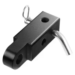
There are two ways to assemble the tools:
Lug Wrench
Long Extension Without Spring Clip 2
Long Extension With Spring Clip 3
Long Extension With Spring Clip 4
Assembled For Jack Operation
Lug Wrench
Long Extension 2
Long Extension 3
Long Extension 4
Short Extension With Hook
SPARE TIRE REMOVAL
Remove the spare tire before attempting to jack up the truck. Attach the lug wrench to the extension tubes with the curved angle facing away from the vehicle.
Insert the extension tube through the access hole between the lower tailgate and the top of the fascia/bumper and into the winch mechanism tube.
Rotate the lug wrench handle counterclockwise until the spare tire is on the ground with enough cable slack to allow you to pull it out from under the vehicle.
Pull the spare tire out from under the vehicle to gain access to the spare tire retainer.
Lift the spare tire with one hand to give clearance to tilt the retainer at the end of the cable.
Pull the retainer through the center of the wheel.
JACKING INSTRUCTIONS
Remove the spare tire, jack and tools from the stored location.
Using the lug wrench, loosen the wheel nuts (but do not remove) by turning them counterclockwise one turn while the wheel is still on the ground.
Assemble the jack and jacking tools. Connect the jack handle driver to the extension, then to the lug wrench
Operate the jack from the front or the rear of the vehicle. Place the jack under the axle tube, as shown. Placement for the front and rear jacking locations are critical. See below images for proper jacking locations. Do not raise the vehicle until you are sure the jack is fully engaged.
Raise the vehicle by turning the jack screw clockwise. Raise the vehicle only until the tire just clears the ground surface and enough clearance is obtained to install the spare tire. Minimum tire lift provides maximum stability.
Remove the lug nuts and wheel.
Mount the spare tire on the axle.
Install the lug nuts with the cone-shaped end toward the wheel. Lightly tighten the lug nuts clockwise.
Lower the vehicle by turning the jack screw counterclockwise, and remove the jack.
Finish tightening the wheel bolts. Push down on the wrench while at the end of the handle for increased leverage. Tighten the wheel bolts in a star pattern until each wheel bolt has been tightened twice page 483. If in doubt about the correct tightness, have them checked with a torque wrench by an authorized dealer or at a service station.
After 25 miles (40 km), check the lug nut torque with a torque wrench to ensure that all lug nuts are properly seated against the wheel.
Remove the jack assembly and wheel blocks.
Secure the jack and tools in their proper locations
TO STOW THE FLAT OR SPARE
Turn the wheel so that the valve stem is facing upward and toward the rear of the vehicle for convenience in checking the spare tire inflation. Slide the wheel retainer through the center of the wheel.
Lift the spare tire with one hand to give clearance to tilt the retainer at the end of the cable and position it properly across the wheel opening.
Attach the lug wrench to the extension tubes with the curved angle facing away from the vehicle. Insert the extension tubes through the access hole between the lower tailgate and the top of the fascia/bumper and into the winch mechanism tube.
Rotate the lug wrench handle clockwise until the wheel is drawn into place against the underside of the vehicle. Continue to rotate until you feel the winch mechanism slip, or click three or four times. It cannot be overtightened. Push against the tire several times to ensure it is firmly in place.
NOTE:
The winch mechanism is designed for use with the extension tube only. Use of an air wrench or other power tools is not recommended and can damage the winch.
REINSTALLING THE JACK AND TOOLS
Tighten the jack all the way down by turning the jack turn-screw counterclockwise until the jack is snug.
Position the jack and tool bag. Make sure the lug wrench is under the jack near the jack turn-screw.
Secure the tool bag straps to the jack.
Place the jack and tools in the storage position holding the jack by the jack turn-screw, place the jack and tools under the rear seat.
Turn the wing bolt clockwise to secure to the floor pan.
JUMP STARTING
If your vehicle has a discharged battery, it can be jump started using a set of jumper cables and a battery in another vehicle, or by using a portable battery booster pack. Jump starting can be dangerous if done improperly, so please follow the procedures in this section carefully.
SERVICING AND MAINTENANCE
SCHEDULED SERVICING - GASOLINE ENGINE
Your vehicle is equipped with an automatic oil change indicator system. The oil change indicator system will remind you that it is time to take your vehicle in for scheduled maintenance.
Based on engine operation conditions, the oil change indicator message will illuminate. This means that service is required for your vehicle. Operating conditions such as frequent short-trips, trailer tow, or extremely hot or cold ambient temperatures will influence when the “Change Oil" or “Oil Change Required" message is displayed. Have your vehicle serviced as soon as possible, within the next 500 miles (805 km).
On vehicles equipped with an instrument cluster display, “Oil Change Required" will be displayed and a single chime will sound, indicating that an oil change is necessary.
On vehicles not equipped with an instrument cluster display, “Change Oil" will flash in the instrument cluster odometer and a single chime will sound, indicating that an oil change is necessary.
An authorized dealer will reset the oil change indicator message after completing the scheduled oil change. To reset the system follow the steps described page 121.
NOTE:
Under no circumstances should oil change intervals exceed 10,000 miles (16,000 km),
12 months or 350 hours of engine run time, whichever comes first. The 350 hours of engine run or idle time is generally only a concern for fleet customers.
Once A Month Or Before A Long Trip:
Check engine oil level
Check windshield washer fluid level
Check the tire pressures and look for unusual wear or damage, rotate at the first sign of irregular wear
Check the fluid levels of the coolant reservoir, brake master cylinder, and power steering, and fill as needed
Check function of all interior and exterior lights
Maintenance Plan
Refer to the maintenance plan for the required maintenance intervals.
At Every Oil Change Interval As Indicated By Oil Change Indicator System:
Change oil and filter
Rotate the tires
NOTE: Rotate at the first sign of irregular wear, even if it occurs before the oil indicator system turns on
Inspect battery and clean and tighten terminals as required
Inspect the CV/Universal joints
Inspect brake pads, shoes, rotors, drums, hoses and parking brake
Inspect engine cooling system protection and hoses
Inspect exhaust system
Inspect engine air cleaner filter if using in dusty or off-road conditions, replace engine air cleaner filter if necessary •
Inspect all door latches for presence of grease, reapply if necessary
NOTE: Using white lithium grease, lubricate the door hinge joints twice a year to prevent premature
1. The spark plug change interval is mileage based only, yearly intervals do not apply.
SCHEDULED SERVICING - DIESEL ENGINE
Your vehicle is equipped with an automatic oil change indicator system. The oil change indicator system will remind you that it is time to take your vehicle in for scheduled maintenance.
Based on engine operation conditions, the oil change indicator message will illuminate. This means that service is required for your vehicle. Operating conditions such as frequent short-trips, trailer tow, extremely hot or cold ambient temperatures will influence when the “Oil Change Required" message is displayed. Have your vehicle serviced as soon as possible, within the next 500 miles (805 km).
ENGINE COMPARTMENT
3.6L ENGINE
Power Distribution Center (Fuses)
Battery
Engine Oil Dipstick
Engine Oil Fill
Engine Coolant Reservoir
Engine Coolant Pressure Cap
Brake Fluid Reservoir Cap
Washer Fluid Reservoir Cap
Power Steering Fluid Reservoir Cap
Engine Air Cleaner Filter
3.0L DIESEL ENGINE
Battery
Engine Oil Fill
Coolant Pressure Reservoir
Brake Fluid Reservoir Cap
Washer Fluid Reservoir Cap
Engine Air Cleaner Filter
Engine Oil Dipstick
Power Steering Reservoir Cap
Power Distribution Center (Fuses)
Checking Oil Level
To ensure proper engine lubrication, the engine oil must be maintained at the correct level. Check the oil level at regular intervals, such as every fuel stop. The best time to check the engine oil level is about five minutes after a fully warmed up engine is shut off.
Checking the oil while the vehicle is on level ground will improve the accuracy of the oil level readings.
There are four possible dipstick types:
Crosshatched zone.
Crosshatched zone marked SAFE.
Crosshatched zone marked with MIN at the low end of the range and MAX at the high end of the range.
Crosshatched zone marked with dimples at the MIN and the MAX ends of the range.
NOTE:
Always maintain the oil level within the crosshatch markings on the dipstick.
Adding 1 quart (1 liter) of oil when the reading is at the low end of the dipstick range will raise the oil level to the high end of the range marking.
Maintenance-Free Battery
Your vehicle is equipped with a maintenance-free battery. You will never have to add water, and periodic maintenance is not required.
VEHICLE MAINTENANCE
An authorized dealer has the qualified service personnel, special tools, and equipment to perform all service operations in an expert manner. Service Manuals are available which include detailed service information for your vehicle. Refer to these Service Manuals before attempting any procedure yourself.
NOTE:
Intentional tampering with emissions control systems may void your warranty and could result in civil penalties being assessed against you.
Engine Air Cleaner Filter
For the proper maintenance intervals see page 410 for gas engines or page 415 for diesel engines.
NOTE:
Be sure to follow the “Severe Duty Conditions" maintenance interval if applicable.
Engine Air Cleaner Filter Selection
The quality of replacement engine air cleaner filter varies considerably. Only high quality Mopar® filters should be used.
Engine Air Cleaner Filter Inspection and Replacement — Gasoline Engine
Follow the recommended maintenance intervals as shown in the Maintenance Schedule in this section.
COOLING SYSTEM
Coolant Checks
Check the engine coolant (antifreeze) protection every 12 months (before the onset of freezing weather, where applicable). If the engine coolant is dirty or rusty in appearance, the system should be drained, flushed, and refilled with fresh Organic Additive Technology (OAT) coolant (conforming to MS.90032) by an authorized dealer. Check the front of the A/C condenser (if equipped) or radiator for any accumulation of bugs, leaves, etc. If dirty, clean by gently spraying water from a garden hose vertically down the face of the A/C condenser (if equipped) or the back of the radiator core. Check the engine cooling system hoses for brittle rubber, cracking, tears, cuts, and tightness of the connection at the coolant recovery bottle and radiator. Inspect the entire system for leaks. DO NOT REMOVE THE COOLANT PRESSURE CAP WHEN THE COOLING SYSTEM IS HOT.
Cooling System — Drain, Flush, And Refill
Some vehicles require special tools to add coolant properly. Failure to fill these systems properly could lead to severe internal engine damage. If any coolant is needed to be added to the system please contact an authorized dealer. If the engine coolant (antifreeze) is dirty or contains visible sediment, have an authorized dealer clean and flush with OAT coolant (conforming to MS.90032). For the proper maintenance intervals see page 410 for gas engines or page 415 for diesel engines.
Transfer Case
Fluid Level Check
The fluid level should be to the bottom edge of the fill hole when the vehicle is in a level position.
Fill Hole
Drain Hole
Drain And Refill
For the proper maintenance intervals page 410.
Selection Of Lubricant
Use only the manufacturer's recommended fluid page 495.
Manual Transmission — If Equipped
Fluid Level Check
Check the fluid level by removing the fill plug. The fluid level should be between the bottom of the fill hole and a point not more than 3/16 of an inch (4.76 mm) below the bottom of the hole.
Add fluid, if necessary, to maintain the proper level.
Frequency Of Fluid Change
Under normal operating conditions, the fluid installed at the factory will give satisfactory lubrication for the life of the vehicle. If the fluid becomes contaminated with water, it should be changed immediately. Otherwise, change the fluid as recommended in the Maintenance Plan page 410.
Selection Of Lubricant
It is important to use the proper transmission fluid to ensure optimum transmission performance and life. Use only manufacturer's specified transmission fluid page 495. It is important to maintain the transmission fluid at the correct level using the recommended fluid.
NOTE: No chemical flushes should be used in any transmission; only the approved lubricant should be used.
Fuses
General Information
The fuses protect electrical systems against excessive electrical current.
When a device does not work, you must check the fuse element inside the blade fuse for a break/melt.
Also, please be aware that when using power outlets for an extended period of time with the engine off, it may result in vehicle battery discharge.
Fuse Element
Blade Fuse with a good/functional fuse element
Blade fuse with a bad/not functional fuse element (blown fuse)
Power Distribution Center (PDC)
The Power Distribution Center is located in the engine compartment near the battery. This center contains cartridge fuses, mini fuses, and relays. The PDC top cover is labeled with each serviceable fuse/relay location, function, and size.
Bulb Replacement
NOTE:
Lens fogging can occur under certain atmospheric conditions. This will usually clear as atmospheric conditions occur to allow the condensation to change back into a vapor. Turning the lamps on will usually accelerate the clearing process.
Halogen Headlamps
NOTE:
We advise referring to an authorized dealer for service.
See below steps to replace:
Open hood and support using prop rod.
Remove the front grille. Turn the retainers along the top a quarter turn counterclockwise and remove.
Pull the bottom of the grille away, starting at one side and working toward the other.
Remove the three screws holding the headlamp to the vehicle.
Remove lamp from the vehicle.
Remove the lamp from the collar.
Grab the bulb and turn a quarter turn counterclockwise.
Pull the bulb from the housing.
Push connector locking tab to the unlock position.
Remove connector from bulb.
Push connector onto new bulb base, and push the connector locking tab to the lock position.
Reinstall bulb housing. Rotate the bulb a quarter turn clockwise.
Front Park/Turn Signal
NOTE:
We advise referring to an authorized dealer for service.
See below steps to replace:
Remove the front wheel liner fasteners to access bulb sockets.
Turn the socket assembly a quarter turn counterclockwise and remove from housing. Pull the bulb straight from the socket to replace.
STORING THE VEHICLE
If you are storing your vehicle for more than 3 weeks, we recommend that you take the following steps to minimize the drain on your vehicle's battery:
Disconnect the negative cable from the battery.
If your vehicle is equipped with Stop/Start system then disconnect both the main and supplemental negative battery cables.
Any time you store your vehicle or keep it out of service (i.e., vacation) for two weeks or more, run the air conditioning system at idle for about five minutes in the fresh air and high blower setting. This will ensure adequate system lubrication to minimize the possibility of compressor damage when the system is started again.
If assistance is needed to disconnect the battery system, see an authorized dealer.
Battery Cable Disconnect
Supplemental Negative Battery Cable
Main Negative Battery Cable
Intelligent Battery Sensor (IBS)
Main Negative Battery Terminal
NOTE:
You must isolate the supplemental battery connection point, as well as the main battery terminal from the post, as shown in the image, to fully de-energize both batteries for storage. If assistance is needed to disconnect the battery system, see an authorized dealer.
Do not disconnect the Intelligent Battery Sensor (IBS), or your Stop/Start system may not function for up to 24 hours, due to the IBS being set into learn mode.
BODYWORK
Protection From Atmospheric Agents
Vehicle body care requirements vary according to geographic locations and usage. Chemicals that make roads passable in snow and ice and those that are sprayed on trees and road surfaces during other seasons are highly corrosive to the metal in your vehicle.
Outside parking, which exposes your vehicle to airborne contaminants, road surfaces on which the vehicle is operated, extreme hot or cold weather, and other extreme cond itions will have an adverse effect on paint, metal trim, and underbody protection.
The following maintenance recommendations will enable you to obtain maximum benefit from the corrosion resistance built into your vehicle.
What Causes Corrosion?
Corrosion is the result of deterioration or removal of paint and protective coatings from your vehicle.
The most common causes are:
Road salt, dirt and moisture accumulation
Stone and gravel impact
Insects, tree sap and tar
Salt in the air near seacoast localities
Atmospheric fallout/industrial pollutants
Body And Underbody Maintenance
Cleaning Headlights
Your vehicle is equipped with plastic headlights and fog lights that are lighter and less susceptible to stone breakage than glass headlights.
Plastic is not as scratch resistant as glass and therefore different lens cleaning procedures must be followed.
To minimize the possibility of scratching the lenses and reducing light output, avoid wiping with a dry cloth. To remove road dirt, wash with a mild soap solution followed by rinsing.
Do not use abrasive cleaning components, solvents, steel wool, or other aggressive material to clean the lenses.
PRESERVING THE BODYWORK
Washing
Wash your vehicle regularly. Always wash your vehicle in the shade using Mopar® Car Wash, or a mild car wash soap, and rinse the panels completely with water.
If insects, tar, or other similar deposits have accumulated on your vehicle, use Mopar® Super Kleen Bug and Tar Remover to remove.
Use a high quality cleaner wax, such as Mopar® Cleaner Wax, to remove road film and stains, and to protect your paint finish. Use precautions to not scratch the paint. •
Avoid using abrasive compounds and power buffing that may diminish the gloss or thin out the paint finish.
Special Care
If you drive on salted or dusty roads or if you drive near the ocean, hose off the undercarriage at least once a month.
It is important that the drain holes in the lower edges of the doors, rocker panels, and trunk be kept clear and open.
If you detect any stone chips or scratches in the paint, touch them up immediately.
If your vehicle is damaged due to a collision or similar cause that destroys the paint and protective coating, have your vehicle repaired as soon as possible.
If you carry special cargo such as chemicals, fertilizers, de-icer salt, etc., be sure that such materials are well packaged and sealed.
If a lot of driving is done on gravel roads, consider mud or stone shields behind each wheel.
Use Mopar® Touch Up Paint on scratches as soon as possible. An authorized dealer has touch up paint to match the color of your vehicle.
Appearance Care For Fabric Top Models
To maintain the appearance of your vehicle's interior trim and top, follow these precautions:
Do not run a fabric top through an automatic car wash. Window scratches and wax build-up may result.
Avoid leaving your vehicle unattended with the top down, as exposure to sun or rain may damage interior trim.
Do not use harsh cleaners or bleaching agents on top material, as damage may result.
Do not allow any vinyl cleaner to run down and dry on the paint, leaving a streak.
After cleaning your vehicle's fabric top, always make sure it is completely dry before lowering.
Be especially careful when washing the windows by following the directions for “Care of Fabric Top Windows."
Washing - Use Mopar® Car Wash or equivalent, or mild soap suds, lukewarm water, and a brush with soft bristles. If extra cleaning is required, use Mopar® Convertible Cloth Top Cleaner or equivalent, or a mild foaming cleaner on the entire top, but support the top from underneath.
Rinsing - Be sure to remove all traces of cleaner by rinsing the top thoroughly with clean water. Remember to allow the top to dry before lowering it.
INTERIORS
Carpet Safety Information
Always use carpet designed to fit your vehicle. Only use carpet that does not interfere with the operation of the pedal assemblies. Only operate the vehicle when the carpet is securely attached by the grommets so it cannot slip out of position and interfere with the pedal assemblies or impair safe operation of your vehicle in other ways.
Cleaning Plastic Instrument Cluster Lenses
The lenses in front of the instruments in this vehicle are molded in clear plastic. When cleaning the lenses, care must be taken to avoid scratching the plastic.
Clean with a wet soft cloth. A mild soap solution may be used, but do not use high alcohol content or abrasive cleaners. If soap is used, wipe clean with a clean damp cloth. Dry with a soft cloth.
Leather Surfaces
Mopar® Total Clean is specifically recommended for leather upholstery.
Your leather upholstery can be best preserved by regular cleaning with a damp soft cloth. Small particles of dirt can act as an abrasive and damage the leather upholstery and should be removed promptly with a damp cloth. Stubborn soils can be removed easily with a soft cloth and Mopar® Total Clean. Care should be taken to avoid soaking your leather upholstery with any liquid. Please do not use polishes, oils, cleaning fluids, solvents, detergents, or ammonia-based cleaners to clean your leather upholstery.
NOTE:
If equipped with light colored leather, it tends to show any foreign material, dirt, and fabric dye transfer more so than darker colors.


 Push the red button on the faceplate or touchscreen or press and slide the temperature bar towards the red arrow button on the touchscreen for warmer temperature settings.
 Push the blue button on the faceplate or touchscreen or press and slide the temperature bar towards the blue arrow button on the touchscreen for cooler temperature settings.


 The temperature increases as you turn the temperature control knob clockwise.
 The temperature decreases as you turn the temperature control knob counterclockwise.


 The fuel pump symbol points to the side of the vehicle where the fuel filler door is located page 205.