
Loading ...
Loading ...
Loading ...
11
geappliances.com
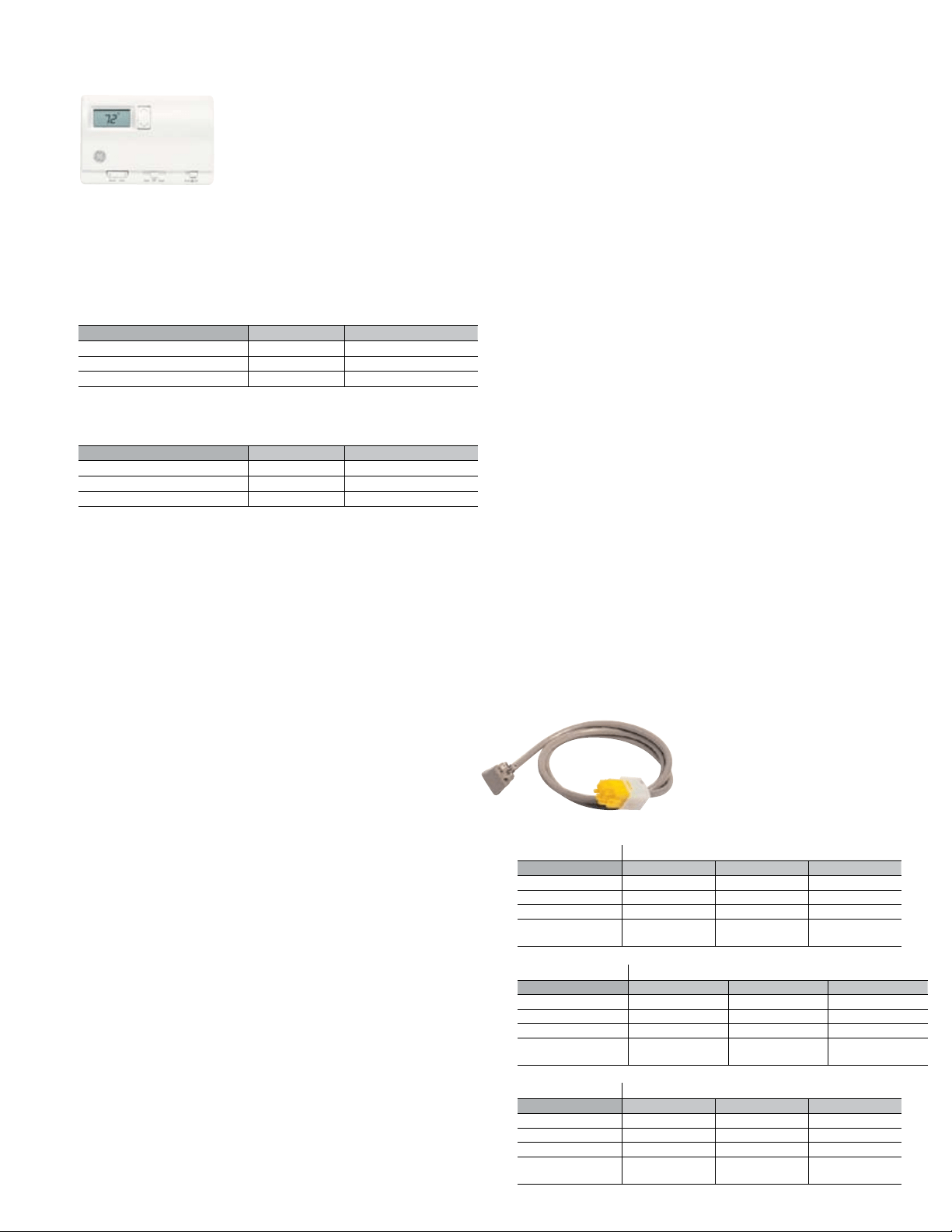
Remote Thermostat
The ZVAC units are controlled by a wall-
mounted thermostat. GE offers a complete
line of thermostats to interface with the units
or most 24-VAC thermostats may be used. If
a non-GE thermostat is used, the compatibility of the thermostat with
the unit is the responsibility of the installer. The unit has an integral
transformer and no external voltage or transformer may be used.
One of the customer-requested features on the ZVAC unit is the
ability for the user to select either HIGH or LOW fan speed operation
at the thermostat. See information on pages 7 and 8.
Maximum wiring length and wire size - AWG 18 up to 66 feet - AWG
20 up to 66 feet - AWG 24 up to 40 feet.
Standard Size Filter (field supplied)
The ZVAC unit uses a standard size 20" by 20" by 1" air
conditioner/furnace filter. The filter is not provided with the unit,
but can be purchased at any building supply or maintenance
equipment supplier. The standard size filter allows the use of
special filters if the owner desires. Regardless of the installation and
the return air method, only one filter may be used in the installation.
Optional: Room Air Temperature Sensor
The Room Air Temperature Sensor accessory, model number
RAVRMS, is available as an option to allow Temperature Limiting and
Freeze Sentinel protection. The Room Air Temperature Sensor has a
nine-foot wiring harness designed to allow the sensor to mount on
the room side of the closet wall. Terminal connectors are located on
the terminal block inside the unit to permit easy connection of the
Room Air Temperature Sensor conductors.
Ductwork (field supplied)
Supply Registers (field supplied)
Ductwork and supply registers are mentioned here as System
Essential Components, because they are necessary to complete
the installation. These components are field supplied since each
installation may have different requirements for the ductwork
and supply registers.
Electrical Information - General
Zoneline Vertical Packaged Terminal Air Conditioners are to be
connected to a single-phase 60 hertz power. Units with the voltage
designator “D” in the 8th character of the model number may be
operated on either nominal 230-volt or 208-volt power. The units are
designed to operate properly on power sources from 197 volts to
253 volts. Units with the voltage designator “E” in the 8th character
of the model number are to be operated on nominal 265-volt power.
This unit is also used on 277-volt power. The units are designed to
operate properly on power sources from 238 volts to 292 volts.
For all installations, feeder, sub-feeder, branch circuit and electrical
protective devices must conform to all local codes. In the absence
of a local code, the National Electrical Code should be followed.
Each unit should be installed on a single branch circuit. More
than one unit per branch circuit is not recommended. All wiring,
including installation of receptacle, must conform to local
electrical regulations and codes. When in doubt, consult the
National Electrical Code.
Power Connection Kits are Required
on Vertical Zoneline
®
Chassis (See chart below.)
The correct kit for the installation is determined by the voltage
and amperage of the electrical circuit and the means of connecting
the unit to the building wiring. If the unit is to be plugged into a
receptacle, a power cord kit would be used; if the unit is to be
permanently connected, a direct connection kit would be used.
Power Connection Kits
See specification sheet for heater
kW and branch circuit ampacity.
RAK3152/3202/3302
230/208 Volt Cord Connection Kit
System Essential Components and Installation
Resistance Heat - Single Stage Cooling/
Single Stage Heating Thermostats
GE Thermostat Model Number Type Low Voltage Conductors
RAK163A1 Mechanical 4
RAK164D1 Digital 5
RAK164P1 Programmable 5
Heat Pump - Single Stage Cooling/
Two Stage Heating Thermostats
GE Thermostat Model Number Type Low Voltage Conductors
RAK147 Mechanical 6
RAK148P1 Programmable 6
RAK148D1 Digital 6
230/208 Volt Line Cord Connected Units
Power Connection RAK3152 RAK3202 RAK3302
Heater kW 2.55/2.09 3.45/2.82 5.0/4.09
Heater Amps 11.0/10.0 15.0/13.6 21.7/19.7
Minimum Circuit Amps
15 20 30
Recommended
Protective Device
15 Amp Time Delay
Fuse or Breaker
20 Amp Time Delay
Fuse or Breaker
30 Amp Time Delay
Fuse or Breaker
265/277 Volt Direct Connected Units
Power Connection RAK5157 RAK5207 RAK5307
Heater kW 2.55 3.45 5.0
Heater Amps 9.7 13.1 18.9
Minimum Circuit Amps
15 20 30
Recommended
Protective Device
15 Amp Time Delay
Fuse or Breaker
20 Amp Time Delay
Fuse or Breaker
30 Amp Time Delay
Fuse or Breaker
230/208 Volt Direct Connected Units
Power Connection RAK4157 RAK4207 RAK4307
Heater kW 2.55/2.09 3.45/2.82 5.0/4.09
Heater Amps 11.0/10.0 15.0/13.6 21.7/19.7
Minimum Circuit 15 20 30
Recommended
Protective Device
15 Amp Time Delay
Fuse or Breaker
20 Amp Time Delay
Fuse or Breaker
30 Amp Time Delay
Fuse or Breaker
Loading ...
Loading ...
Loading ...