Please refer to the engine operator’s manual for engine features and controls.
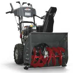
Snowthrower Features and Controls
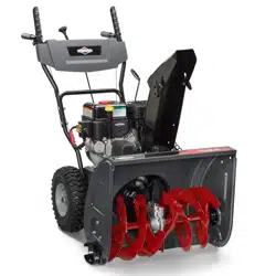
Compare Figure 2 with the table below.
Operation
Before Operating the Snowthrower
WARNING
Read the operator’s manual before operating the machine. This machine can be dangerous if used carelessly.
Never operate the snowthrower without all guards, covers, and shields in place.
Stop the engine whenever leaving the operating position.
Remove the key before unclogging the impeller housing or discharge chute, and before making repairs or adjustments.
When leaving the machine, remove the key.
To reduce the risk of fire, keep the machine clean and free from spilled fuel, oil, and debris.
On electric start models, disconnect the extension cord before operating.
Be sure to check the engine oil level before starting the engine. See the engine operator’s manual for oil recommendations.
Operating the Snowthrower
DANGER
Amputation hazard
The discharge chute contains a rotating impeller to throw snow. Fingers can quickly become caught in the impeller. Never clear or unclog the discharge chute with your hands. Always use a clean-out tool.
Failure to observe these safety instructions will result in traumatic amputation or severe laceration.
Hand contact with the rotating impeller inside the discharge chute is the most common cause of injury associated with snowthrowers. Never use your hands to clean out the discharge chute.
To safely clear a clogged discharge chute, follow these instructions:
Shut OFF the engine.
Wait 10 seconds to be sure the impeller blades have stopped rotating.
Always use a clean-out tool, not your hands.
DANGER
Toxic fume hazard
Engines give off carbon monoxide, an odorless, colorless, poison gas.
Breathing carbon monoxide can cause nausea, fainting, or death.
Start and run the engine outdoors.
Do not run the engine in an enclosed area, even if doors and windows are open.
WARNING
Thrown objects hazard
This machine is capable of throwing objects that could injure bystanders, or cause damage to buildings.
Be sure the operating area is clear of bystanders. Never direct the discharge toward anyone, or toward buildings or cars.
1. Start the engine. Please refer to the engine operator’s manual for instructions.
NOTE: Always set engine speed to FAST (full throttle).
2. Rotate the chute rotation crank (C, Figure 2) to set the direction of the discharge chute.
3. Loosen the wingnut (E) securing the chute deflector. Raise the deflector to throw snow further. Set the deflector to the desired position and tighten the wingnut.
4. Use the speed select lever (B) to select the forward or reverse drive speed. Use lower speeds when clearing wet, heavy snow. Use higher speeds for light snow or transporting.
NOTE: Always release the traction control lever before changing speeds.
5. Fully press the auger control lever (A) to engage the auger. Release the lever to stop the auger.
6. Fully press and hold the traction control lever (D) to engage the traction drive and propel the snowthrower. Release the lever to stop the snowthrower.
Stopping the Snowthrower
1. Release the auger control lever (A, Figure 2).
2. Release the traction control lever (D).
3. Stop the engine. Please refer to the engine operator’s manual for instructions.
Wheel Release - Lock Pins
Wheels equipped with a traction lock pin (A, Figure 3) can be completely released by removing the pin and installing it in the outer axle hole. Reverse this process to engage the drive wheel.
Filling the Fuel Tank
Please refer to the engine operator’s manual for instructions about filling the fuel tank, and for fuel recommendations.
Clearing a Clogged Discharge Chute
DANGER
Amputation hazard
The discharge chute contains a rotating impeller to throw snow. Fingers can quickly become caught in the impeller. Never clear or unclog the discharge chute with your hands. Always use a clean-out tool.
Failure to observe these safety instructions will result in traumatic amputation or severe laceration.
Hand contact with the rotating impeller inside the discharge chute is the most common cause of injury associated with snowthrowers. Never use your hands to clean out the discharge chute.
A clean-out tool (A, Figure 4) is provided with the unit.
To safely clear a clogged discharge chute, follow these instructions:
1. Shut OFF the engine.
2. Wait 10 seconds to be sure the impeller blades have stopped rotating.
3. Always use a clean-out tool, not your hands.
Skid Shoe Heiaht Adjustment
This snowthrower is equipped with two skid shoes secured to the outside of the auger housing. These adjust the height of of the front of the snowthrower.
When removing snow from a hard surface area such as a paved driveway or walk, raise the skid shoes to bring the front of the snowthrower down.
When removing snow from gravel-covered or uneven surfaces, lower the skid shoes to bring the front of the snowthrower up. This will help to prevent rocks and other debris from being picked up and thrown by the augers.
1. Determine the clearance needed between the scraper bar at the bottom of the auger housing and the ground.
2. Place a block with a thickness equal to the desired
3. Loosen the skid shoe mounting nuts (A, Figure 5) and push the skid shoe (B) down until it touches the ground Re-tighten mounting nuts.
4. Set the skid shoe on the other side at the same height.
Maintenance
Maintenance Schedule
Before Each Use
• Check engine oil level
• Perform Safety System Tests
Every 8 Hours or Daily
• Check engine oil level
Every 25 Hours or Annually
• Lubricate control lever linkages
• Lubricate the auger assembly
• Lubricate the discharge chute rotation gear and deflector
• Lubricate the hex shaft and gears
Every 50 Hours or Annually
• Check muffler and spark arrester (if equipped)
• Check tire pressure
Engine Maintenance
Please refer to the engine operator’s manual for engine maintenance schedules and procedures.
Lubricate Control Lever Linkage
Lubricate the control lever linkage at the locations shown in Figure 6.
Lubricate Discharge Chute, Deflector, and Axle Wheel
Lubricate the discharge chute, deflector, and wheel axle at the locations shown in Figure 7.
Lubricate Auger Assembly
Lubricate the auger assembly at the location shown in Figure 8.
Hex Shaft and Gear Lubrication
NOTICE: Do not allow grease or oil to contact the rubber friction wheel or the disc drive plate. If grease or oil comes into contact with the friction wheel, replace it. Do not attempt to clean it. If grease or oil comes into contact with disc drive plate, clean it thoroughly with an alcohol based solvent.
1. Position speed select lever in the first forward gear.
2. Drain fuel to an approved container.
3. Stand the snowthrower up on the auger housing end.
NOTE: When the crankcase is filled with oil, do not leave the snowthrower standing up on the auger housing for an extended period of time.
4. Remove screws (A, Figure 9) and bottom panel (B).
5. Wipe the hex shaft (C, Figure 10) with 5W30 synthetic motor oil, before storage and at the beginning of each season.
6. Install the bottom panel (B, Figure 9) and screws (A).
Auger and Traction Cable Adjustment
NOTE: If the auger or traction cables become stretched or are sagging, adjustment is necessary.
1. Loosen finger nut (A, Figure 11).
2. Hold control cable (B) to keep it from rotating.
NOTE: The cable should not rotate while making adjustment.
3. Turn collar (C) to remove slack but do not over-tighten.
4. Tighten finger nut.
5. Perform snowthrower safety test to ensure proper operation. See Safety System Tests. If necessary, make additional adjustments.
Speed Control Rod Adjustment
If the speed control rod requires adjustment, see an authorized dealer.
Checking Tire Pressure
Tire pressure should be checked periodically. The maximum tire pressure is stamped on the sidewall of the tires. Do not exceed this pressure.
Auger Shear Bolt Replacement
1. Turn the engine OFF, wait for all moving parts to stop, and remove the engine key.
2. Remove the existing shear bolt (A, Figure 12) and locknut (C) from auger shaft (B).
3. Align the bolt holes. Install the replacement shear bolt through the auger shaft. Secure with the locknut.
Gear Box Shear Bolt Replacement
1. Turn the engine OFF, wait for all moving parts to stop, and remove the engine key.
2. Remove the existing shear bolt (A, Figure 13) and locknut (C) from impeller shaft (B).
3. Align the bolt holes. Install the replacement shear bolt through the impeller shaft. Secure with the locknut.
Storage
Equipment
• Thoroughly clean the unit.
• Lubricate the hex shaft (see Maintenance section).
• Make sure all nuts, bolts, and screws are securely fastened. Inspect all visible moving parts for damage, breakage, and wear. Replace if necessary.
• Apply a rust preventative to any bare metal parts of the snowthrower auger and impeller.
• If possible, store the unit indoors and cover it to give protection from dust and dirt.
• If the machine must be stored outdoors, cover it with a heavy tarpaulin.
Fuel System
Fuel can become stale when stored over 30 days. Stale fuel causes acid and gum deposits to form in the fuel system or on essential carburetor parts. To keep fuel fresh, use Briggs & Stratton® Advanced Formula Fuel Treatment & Stabilizer, available wherever Briggs & Stratton genuine service parts are sold.
There is no need to drain gasoline from the engine if a fuel stabilizer is added according to instructions. Run the engine for 2 minutes to circulate the stabilizer throughout the fuel system before storage. If gasoline in the engine has not been treated with a fuel stabilizer, it must be drained into an approved container. Run the engine until it stops from lack of fuel. The use of a fuel stabilizer in the storage container is recommended to maintain freshness.
Engine Oil
While the engine is still warm, change the engine oil. See Changing the Oil in the engine operator’s manual.
Before starting the unit after it has been stored:
• Check all fluid levels. Check all maintenance items.
• Perform all recommended checks and procedures found in this manual.
• Allow the engine to warm up for several minutes before use.
Troubleshooting
Troubleshooting the Snowthrower
Problem
Look for
Remedy
Auger does not stop within 5 seconds after auger control lever is released.
Auger control cable out of adjustment.
Adjust auger control cable. Refer to Maintenance section.
Discharge chute or deflector does not work
Discharge chute or deflector out of adjustment or needs lubrication.
Adjust and/or lubricate control linkage.
Scraper bar does not clean hard surface.
Skid shoes and scraper bar improperly adjusted.
Raise or lower skid shoes and scraper bar.
Unit does not propel itself.
Traction control cable out of adjustment.
Adjust traction control cable. Refer to Maintenance section.
Engine does not start.
Key is in OFF position.
Set key to ON position.
Primer button not pressed (cold engine).
Press primer button twice and restart.
Fuel shut-off valve (if equipped) is in CLOSED position.
Turn valve to OPEN position.
Out of fuel.
Fill fuel tank.
Choke turned to OPEN/RUN) cold engine).
Turn choke to CLOSED/START, set throttle to FAST.
Engine flooded.
Move the choke to OPEN/RUN position, move throttle to FAST position, and crank until the engine starts.
Engine starts hard or runs poorly.
Water in fuel, or old fuel.
Drain tank. (Dispose of fuel at an authorized hazardous waste facility.) Fill with fresh fuel.
Fuel cap vent is blocked.
Clear vent or replace fuel cap.
Excessive vibration.
Loose parts or damaged impeller.
Stop engine immediately. Tighten all hardware. If vibration continues, have the unit serviced by an authorized dealer.
Snowthrower does not stop when traction control lever is released.
Traction control cable out of adjustment.
Adjust traction control cable. Refer to Maintenance section.
Unit does not discharge snow.
Auger control cable out of adjustment.
Adjust auger control cable. Refer to Maintenance section.
Broken auger shear bolt.
Replace auger shear bolt. Refer to Maintenance section.
Broken gear box shear bolt.
Replace gear box shear bolt. Refer to Maintenance section.
Problem
Look for
Remedy
Unit does not discharge snow (continued).
Discharge chute clogged.
Stop engine immediately. Always use the clean-out tool to clear a clogged discharge chute, not your hands. Refer to Discharge Chute Warning in the Operator Safety section.
Foreign object lodged in auger.
Stop engine immediately. Always use the clean-out tool to remove for-eignh object, not your hands. Refer to WARNINGS in the Operator Safety section.
NOTE: For all other problems, contact an Authorized Service Dealer.
Specifications
Engine Brand
Briggs & Stratton
Engine Model Series
Snow Series
Engine Type
4-Cycle
Starting System
Recoil Start and Electric Start 110V 1-2-3 Start Package (if equipped)


 WARNING