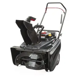
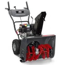
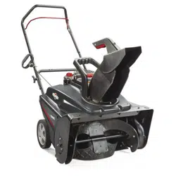
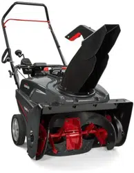
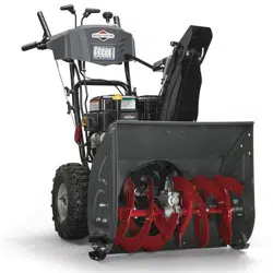
Briggs & Stratton 1696619 Blower
Product's Documents
Below are documents related to this product, you can read online or download:
- Owner's manual - (English) Read Online | Download pdf
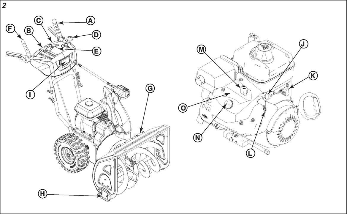
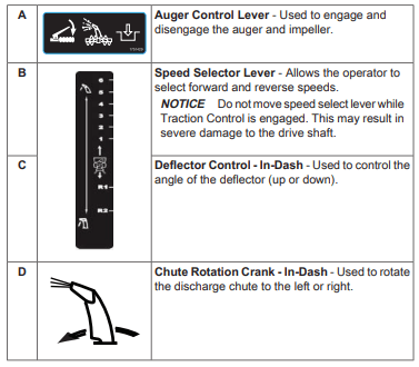
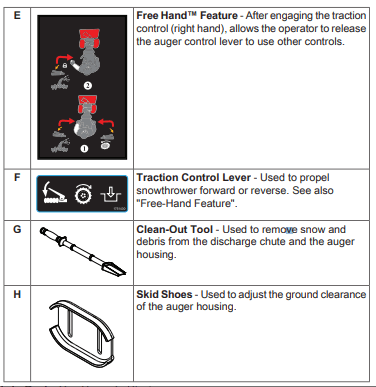
Match the call out letters in Figure 2 to the features and controls listed in the accompanying table
WARNING: This snowthrower is only as safe as the operator. If it is misused, or not properly maintained, it can be dangerous. Remember you are responsible for your safety and those around you.
1. Familiarize yourself with the area in which you plan to operate the snowthrower. Mark off all boundaries of walkways and driveways.
2. Ensure the area to be cleared is free of debris or objects that could be picked up by the auger and thrown from the chute.
WARNING  : This machine is capable of throwing objects that could injure bystanders or cause damage to buildings.
3. Before starting the engine, move the snowthrower outdoors and away from windows and doors.
WARNING  : Engines give off carbon monoxide, an ordorless, colorless, poison gas. Breathing carbon monoxide can cause nausea, fainting, or death.
4. Ensure the operating area is clear of bystanders, especially children.
WARNING  : This snowthrower is capable of amputating hands and feet, and throwing objects. Read and observe all the safety instructions in this manual. Failure to do so could result in death or serious injury.
NOTICE
The engine was shipped from the factory without oil. Before you start the engine, ensure that you add oil according to the instructions in this manual. If you start the engine without oil, it will be damaged beyond repair and will not be covered under the warranty.
Use Briggs & Stratton Synthetic 5W-30 Warranty Certified oil for best performance. Other high-quality detergent oils are acceptable if classified for service SG, SH, SJ or higher. Do not use any additives.

Fuel must meet these requirements:
NOTICE
Do not use unapproved gasolines, such as E15 and E85. Do not mix oil in gasoline or modify the engine to run on alternate fuels. Use of unapproved fuels will cause engine damage that will not be covered under warranty.
At altitudes over 5,000 feet (1524 meters), a minimum 85 octane / 85 AKI (89 RON) gasoline is acceptable. To remain emissions compliant, high altitude adjustment is required. Operation without this adjustment will cause decreased performance, increased fuel consumption, and increased emissions. See an authorized service dealer for high altitude adjustment information. Operation altitudes below 2,500 feet (762 meters) with the high altitude adjustment is not recommended.
WARNING  :
:
Fuel and its vapors are extremely flammable and explosive. Always handle fuel with extreme care.
Failure to observe these safety instructions can cause a fire or explosion which could result in serve burns or death
Starting Engine
WARNING  :
:
Fuel and its vapors are extremely flammable and explosive. Always handle fuel with extreme care.
Failure to observe these safety instructions can cause a fire or explosion which could result in serve burns or death.
1. Ensure the auger control (A, Figure 5) and traction control (K) are disengaged.
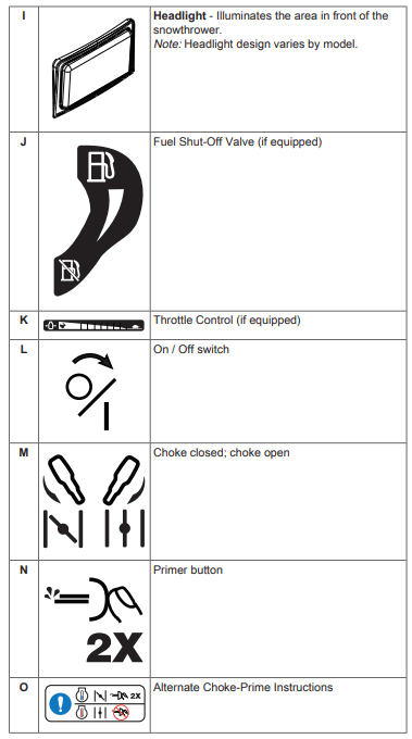
2. Turn the fuel shut-off valve (C) (if equipped) to the Open position.
3. Move the throttle control (D) (if equipped) to the Fast position.
4. Insert the ignition key (E) and turn it to the ON position or insert the push/pull key.
5. Turn the choke control (F) to the Closed position.
Note: Choke is usually not needed when starting a warm engine.
6. Press the primer (G) two times.
Note: Primer is usually not needed when starting a warm engine.
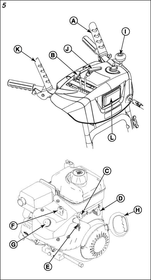
7. For rewind start: Firmly hold the starter cord handle (H). Pull the handle slowly until resistance is felt, then pull rapidly.
WARNING  : Rapid retraction of the starter cord (kickback) will pull your hand and arm toward the engine faster than you can let go. Broken bones, fractures, bruises, or sprains could result.
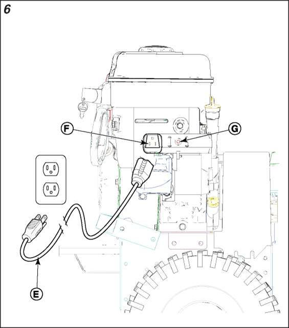
8. For electric start: Connect the extension cord (E, Figure ^ 6) to the starter box (F) on the engine, and then to the wall receptacle. Press the starter box pushbutton (G). After the engine starts, disconnect the extension cord from the wall ^ receptacle and then from the starter box.
WARNING  : Damaged or ungrounded power cords could cause electric shock. Electric shock could cause severe burns or death.
NOTICE To extend the life of the starter, use short starting cycles (five seconds maximum). Wait one minute between starting attempts.
If the engine does not start after repeated attempts, contact an authorized service dealer or go to our website.
9. Allow the engine to warm up for several minutes. Gradually move the choke control (F, Figure 5) to the Open position
WARNING
Ice, gravel, or other unintended objects can be picked up by the auger and thrown from the chute with force
Objects thrown from the chute could cause death, serious injury, or property damage
Note: Always release the traction control lever before changing speeds.
The auger and impeller work together to break up the snow as the snowthrower moves forward and throws it out the discharge chute.
DANGER  : The snowthrower contains a rotating auger and impeller to throw snow. Fingers or feet can quickly become caught in the auger or impeller resulting in traumatic amputation or severe laceration.
NOTICE: Do not move the speed select control while the traction control is engaged. This may result in damage to the drive system.
1. To drive forward, shift the speed select control (B, Figure 5) into one of the forward positions. Select a lower number for heavy snow, a middle number for light snow, and a higher number for moving without snow removal.
2. Press and hold down the traction control (K) on the right handle.
3. To stop, release the traction control. Unit must stop immediately. If it does not;
4. To drive backward, shift the speed select control into one of the reverse positions.
5. Press and hold down the traction control on the right handle.
6. To stop, release the traction control. Unit must stop immediately. If it does not;
NOTICE: Do not overload the machine capacity by attempting to clear snow at too fast of a rate.
Some models are equipped with the Free Hand™ feature, which allows the operator to release the auger control to reach other controls without stopping the unit. If your model is equipped with Free Hand, it will have the decal shown in Figure 7 affixed to the dash panel.
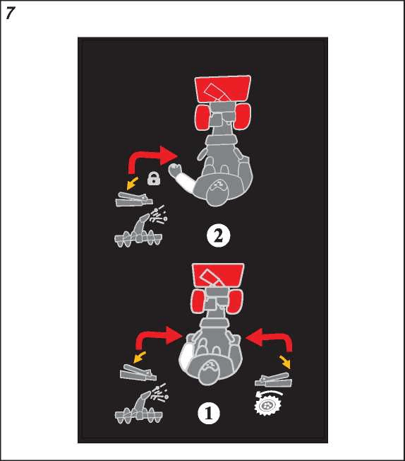
Note: Free Hand cannot be actuated by releasing the traction control.
DANGER ® : The discharge chute contains a rotating impeller to throw snow. Fingers can quickly become caught in the impeller resulting in traumatic amputation or severe laceration. Never clear a clogged discharge chute with your hands. Always use a clean-out tool.
To safely clear a clogged discharge chute, follow these instructions:
Some models are equipped with a headlight (L, Figure 5) to help illuminate the area in front of the snowthrower. The headlight is on whenever the engine is running. There is no switch
One or both wheels can be temporarily disengaged from the drive axles for ease of handling when transporting the unit.
1. Open the pull ring (A, Figure 10) over the wheel hub.
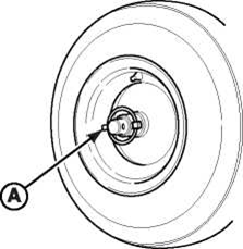
2. Insert the retaining pin through the outer hole in the axle and close the pull ring over the axle.
3. To engage the wheel and axle, align the wheel hub and the inner axle hole, then install the retaining pin fully and close the pull ring over the wheel hub.
We recommend contacting an authorized service dealer for all maintenance, adjustments, and servicing of the unit. Some routine maintenance tasks can be performed by the owner. Refer to the maintenance schedule and procedures that follow.
CAUTION: All the components used to build this product must remain in place for proper operation. Replacement parts must be of the same design and installed in the same position as the orginial parts. Other parts may not perform as well, may damage the unit, and may result in injury.
WARNING  : This snowthrower must be properly maintained to ensure safe operation and performance. Failure to observe the safety instructions in this manual could result in death or serious injury
First 5 Hours
Change oil
Before Each Use
After Each Use
Remove accumulated snow and slush to prevent freezing of the controls, wheels, discharge chute, and auger
Every 25 Hours or Annually
Maintenance, replacement, or repair of the emissions control devices and systems may be performed by any non-road engine repair establishment or individual. However, to obtain “no charge” emissions control service, the work must be performed by a factory authorized dealer.
Used oil must be disposed of properly. Do not discard with household waste. Check with your local authorities, service center, or dealer for safe disposal or recycling facilities.
Use Briggs & Stratton Synthetic 5W-30 Warranty Certified oil for best performance. Other high-quality detergent oils are acceptable if classified for service SG, SH, SJ or higher. Do not use any additives.
1. With the engine stopped but still warm, turn the ignition key to the OFF position and remove it or pull out the push/pull key (if equipped).
WARNING  : Fuel and its vapors are extremely flammable, which could cause burns or fire resulting in death or serious injury.
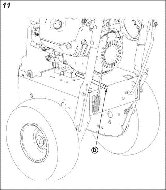
2. Remove the oil drain plug (D, Figure 11) and tilt the snowthrower slightly to drain the oil into an appropriate container.
3. After the oil has drained, install and tighten the oil drain plug (D).
4. Place the unit on a level surface.
5. Clean the oil fill area of any moisture or debris.
6. Remove the dipstick (A, Figure 12) and wipe it with a clean cloth. Set it aside.
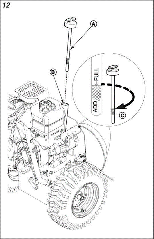
7. To add oil, pour slowly into the engine oil fill tube (B). See Specifications for the oil capacity. Do not overfill.
8. Wait one minute before checking the oil level.
9. Insert and tighten the dipstick, then remove it again to check the oil level. It should be at the top of the full indicator (C).
10. When the oil level is at the top of the full indicator, install and tighten the dipstick.
DANGER 
This snowthrower contains a rotating auger to collect snow. Fingers can quickly become caught and traumatic amputation or severe laceration will result.
Turn the engine OFF, wait for all moving parts to stop, and remove the ignition key or push/pull key before performing any maintenance or repairs.
WARNING 
lf struck by the auger or impeller, objects such as gravel, rocks, or other debris may be thrown with sufficient force to cause personal injury, property damage, or damage to the snowthrower.
Skids shoes are secured to either side of the auger housing. They can be adjusted to increase or decrease the distance between the scraper bar and the surface to be cleared.
Set the skid shoes at the proper height to maintain ground clearance for the type of surface being cleared.
1. Shut the engine off and remove the key.
2. Determine the scraper bar clearance needed for the surface to be cleared
3. Place the unit on a level surface
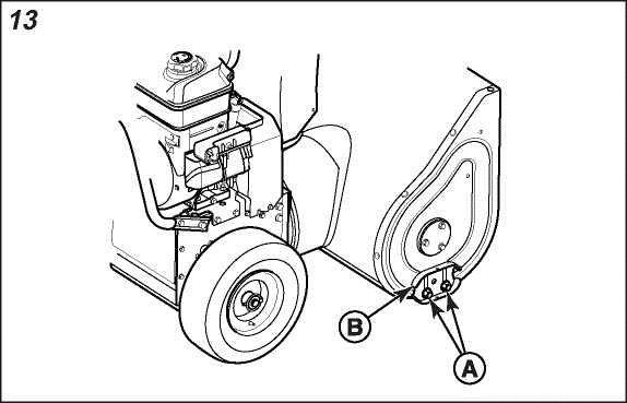
4. Loosen the skid shoe mounting nuts (A, Figure 13) on the skid shoe (B).
5. Under each end of the scraper bar, place a wooden block of the same thickness as the desired clearance height.
6. Allow each skid shoe to firmly touch the surface. Then tighten the mounting nuts.
NOTICE: To prevent contact with the auger, ensure the mounting nuts are to the outside of the auger housing.
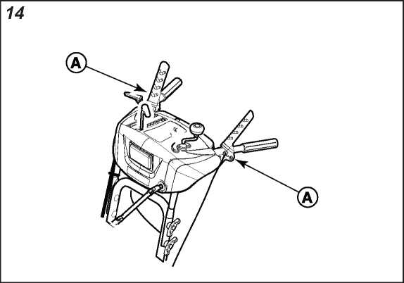
Lubricate the control lever linkage (A) at the locations shown in Figure 14. Use fresh, clean engine oil.
NOTICE: Do not allow grease or oil to contact the rubber friction wheel or the disc drive plate. If grease or oil comes into contact with the friction wheel, replace it. Do not attempt to clean it. If grease or oil comes into contact with disc drive plate, clean it thoroughly with an alcohol based solvent.
1. Shut off the engine and remove the key.
2. Position speed select lever in the first forward gear.
WARNING: Fuel and its vapors are extremely flammable, which could cause burns or fire resulting in death of serious injury.
3. Stand the snowthrower up on the auger housing end.
Note: When the crankcase is filled with oil, do not leave the snowthrower standing up on the auger housing for an extended period of time.
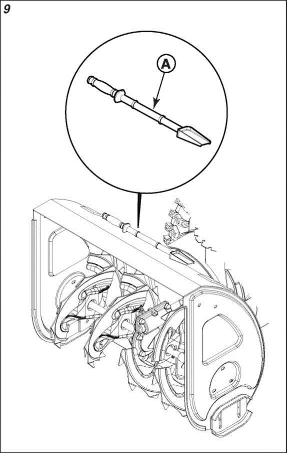
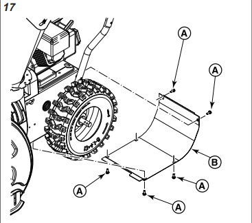
4. Remove screws (A, Figure 17) and bottom panel (B).
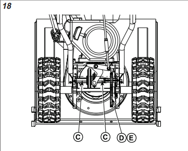
5. Wipe the hex shaft (C, Figure 18) with motor oil, before storage and at the beginning of each season.
6. Lubricate the sprocket (D) and chain (E) with motor oil, before storage and at the beginning of each season.
7. Install the bottom panel (B, Figure 17) and screws (A)
DANGER^: The snowthrower contains a rotating auger and impeller to throw snow. Fingers or feet can quickly become caught in the auger or impeller resulting in traumatic amputation or severe laceration.
Follow the adjustment procedure to ensure the cables are not over-tightened.
The auger and impeller should rotate only when the auger control is engaged and must stop within 5 seconds when the auger control is released. If the auger and impeller do not rotate or do not stop as described, adjust the control cable or contact an authorized service dealer to adjust the control cable.
The unit should only move when the traction control is engaged and must stop immediately when the traction control is released. If the unit does not stop as described, adjust the control cable or contact an authorized service dealer to adjust the control cable.
1. Shut off the engine and remove the key.
2. Loosen jam nut (A, Figure 19).
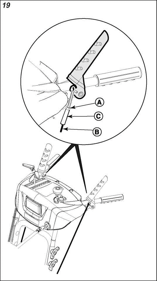
3. Hold control cable (B) to keep it from rotating.
Note: The cable should not rotate while making adjustment.
4. Turn collar (C) to remove slack but do not over-tighten.
5. Tighten jam nut.
6. After adjustment, check the operation of the auger and traction controls, as well as the Free Hand feature using the tests below:
Test 1 -Auger/lmpeller Control
With the engine running:
Test 2 - Traction Drive Control
With the engine running and speed control in 1st gear:
Test 3 - Free Hand Feature
With the engine running:
7. If the unit does not operate as described, DO NOT use it. Contact an authorized service dealer to have the unit inspected and adjusted or repaired.
DANGER  : The snowthrower contains a rotating auger and impeller to throw snow. Fingers or feet can quickly become caught in the auger or impeller resulting in traumatic amputation or severe laceration.
1. Shut off the engine and remove the engine key.
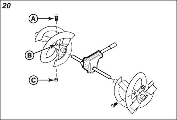
2. Remove the existing shear bolt (A, Figure 20) and locknut (C).
3. Add grease at the auger grease fittings, (if equipped). Spin the auger to lubricate the auger shaft.
Note: Some models are not equipped with grease fittings and are exempt from this step.
4. Align the bolt holes. Install the new shear bolt through the auger shaft (B). Secure with the locknut (C).
DANGER  : The snowthrower contains a rotating auger and impeller to throw snow. Fingers or feet can quickly become caught in the auger or impeller resulting in traumatic amputation or severe laceration.
WARNING 
Explosion hazard
Over-inflation of tires may cause them to explode, which could result in serious injury.
Do not inflate the tires above the maximum pressure.
Tire pressure should be checked periodically. Recommended tire pressure varies by tire manufacturer. A good rule of thumb is to inflate the tire up to, but not exceeding, the “Max Inflation” stamped on the side-wall of the tire.
At the end of the season, or whenever the unitwill be stored for 30 days or more, follow the storage checklist below.
WARNING  : Gasoline is highly flammable and its vapors are explosive. Fumes may travel to a distant ignition source and an explosion and/or fire may result.
Engine:
Fuel can become stale when stored more than 30 days. Stale fuel can cause acids and gum deposits to form in the fuel system and the carburetor. To keep fuel fresh, add Briggs & Stratton Advanced Formula Fuel Treatment and Stabilizer.
Snowthrower:
Returning the unit to Service:
Perform the inspection or repair as indicated in the Troubleshooting Chart.
| Problem | Look for | Remedy |
Auger does not stop within 5 seconds after auger control lever is released. | Auger control cable out of adjustment. | See Adjusting the Auger and Traction Cable. |
Discharge chute or deflector does not work. | Discharge chute or deflector out of adjustment or needs lubrication. | Adjust and/or lubricate control linkage. |
Scraper bar does not clean hard surface. | Skid shoes and scraper bar improperly adjusted. | See Adjusting the Skid Shoe Height. |
Unit does not propel itself. | Traction control cable out of adjustment. | See Adjusting the Auger and Traction Cable. |
Engine does not start. | Key is in OFF position. | Turn key to ON position. |
| Primer button not pressed (cold engine). | Press primer button twice and restart. | |
Fuel shut-off valve (if equipped) is in CLOSED position. | Turn valve to OPEN position. | |
Out of fuel. | Fill fuel tank. | |
Choke turned to OPEN/RUN (cold engine). | Turn choke to CLOSED/START, set throttle to FAST. | |
| Engine flooded | Move the choke to OPEN/RUN position, move throttle to FAST position, and crank until the engine starts. | |
Engine starts hard or runs poorly. | Water in fuel, or old fuel. | Fill with fresh fuel. |
Fuel cap vent is blocked. | Clear vent or replace fuel cap. | |
Excessive vibration. | Loose parts or damaged impeller. | Stop engine immediately. Tighten all hardware. If vibration continues, have the unit serviced by an Authorized Dealer |
Snowthrower does not stop when traction control lever is released. | Traction control cable out of adjustment. | See Adjusting the Auger and Traction Cable. |
Unit does not discharge snow. | Auger control cable out of adjustment. | See Adjusting the Auger and Traction Cable. |
Broken auger shear bolt. | See Replacing the Auger Shear Bolt. | |
Broken impeller shear bolt. | See Replacing the Auger Shear Bolt. | |
Discharge chute clogged. | STOP THE ENGINE! Ensure that the auger and impeller have stopped rotating. Use a clean-out tool to remove snow from the discharge chute. Never clear a clogged discharge chute with your hands! See Clearing a Clogged Discharge Chute. | |
Foreign object lodged in auger. | STOP THE ENGINE! Ensure that the auger and impeller have stopped rotating. Use a clean-out tool to remove foreign object. Never clear a lodged object with your hands! See Clearing a Clogged Discharge Chute. |
For all other issues, contact an authorized service dealer.
The spark ignition system on this snowthrower complies with Canadian standard ICES-002.
Item | Model 130000 | Model 150000 |
Armature air gap | .010 - .014 inch (,25 - ,36 mm) | .010 - .014 inch (,25 - ,36 mm) |
Intake Valve Clearance | .004 - .006 inch (,10 - ,15 mm) | .004 - .006 inch (,10 - ,15 mm) |
Exhaust Valve Clearance | .006 - .008 inch (,15 - ,20 mm) | 009-.011 inch (,23-,28 mm) |
Oil Capacity | 18-20 oz(,54- ,59 L) | 18 - 20 oz (,54-,59 L) |
Sparkplug gap | 030 inch (,76 mm) | .030 inch (,76 mm) |
Engine power will decrease 3.5% for every 1,00 feet (300 meters) above sea level and 1 % for every 10 degrees F (5.6 degrees C) above 77 Degrees F (25 Degrees C). The engine will operate satisfactorily at an angle up to 15 degrees.
The gross power rating for individual gasoline engine models is labeled in accordance with SAE (Society of Automotive Engineers) code J1940 Small Engine Power & Torque Rating Procedure, and is rated in accordance with SAE J1995. Torque values are derived at 2600 RPM for those engines with “rpm” called out on the label and 3060 RPM for all others; horsepower values are derived at 3600 RPM. The gross power curves can be viewed at. Net power values are taken with exhaust and air cleaner installed whereas gross power values are collected without these attachments. Actual gross engine power will be higher than net engine power and is affected by, among other things, ambient operating conditions and engine-to-engine variability. Given the wide array of products on which engines are placed, the gasoline engine may not develop the rated gross power when used in a given piece of power equipment. This difference is due to a variety of factors including, but not limited to, the variety of engine components (air cleaner, exhaust, charging, cooling, carburetor, fuel pump, etc.), application limitations, ambient operating conditions (temperature, humidity, altitude), and engine-to-engine variability. Due to manufacturing and capacity limitations, Briggs & Stratton may substitute an engine of higher rated power for this engine.