Loading ...
Loading ...
Loading ...
EN – 11
3. Release attachment clutch lever.
4. Align holes in mount brackets with holes in frame and
secure housing to frame with two hex bolts, but DO
NOT tighten.
IMPORTANT: Unit must be on a flat, level surface during
steps 5 – 7.
5. Check tire pressure and adjust if necessary. Refer to
Operator’s Manual for specification.
6. Torque hex bolts installed in step 4 to
33.8 – 70.1 N•m (24.9 – 51.7 lb-ft).
7. Loosen skid shoe hardware and adjust skid shoes.
Refer to Operator’s Manual for adjustment procedure.
See Figure 14.
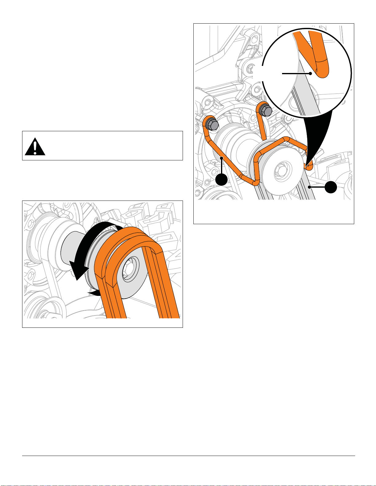
8. Reinstall attachment drive belts onto attachment
sheave.
To assist belt installation, slowly pull recoil starter handle
while gently guiding belts onto attachment sheave.
See Figure 15.
9. Reinstall belt finger and secure with two flat steel
washers, two locking washers and two hex bolts.
10. Check belt finger clearance:
• Engage attachment clutch lever and make sure belt
finger located opposite belt idler is less than 3.2 mm
(1/8") from belt, but not touching the belt.
• If needed, adjust clearance by loosening hex bolts,
repositioning belt finger, and tightening bolts.
11. Reinstall belt cover and secure left side with tapping
screw. Position right side under tapping screw and
tighten.
IMPORTANT: For Model 921326, advance to step 15.
Models 921045, 921046, 921047, 921048, 921049,
921323, 921324, 921325
12. Reinstall short end of chute rotation rod into dash
panel until opposite end clears chute gears.
13. Insert chute rotation rod into chute gear and secure
with spring clip.
14. Advance to step 20.
Model 921326
15. Insert hex rod end without ears into dash panel until
opposite end clears chute gears.
16. Position discharge chute facing forward.
17. Position chute rotation lever upright and insert hex rod
through chute gear until it stops. Secure with hairpin.
18. Insert chute lock cable through hole in dash panel and
insert cable snap into chute control assembly.
19. Remove hairpin from chute control assembly and
reinstall cable eyelet onto assembly. Reinstall hairpin.
See Figure 4.
All Models
20. Reinstall gear cover and secure with tapping screw.
21. Reinstall chute deflector cable into J-clamp on engine
mount.
WARNING: AVOID INJURY. Attachment sheave
edges are sharp. Wear thick gloves to install
belts onto attachment sheave.
Figure 14
Figure 15
1. Belt Finger
2. Attachment Drive Belts
Measure
Here
1
2
Loading ...
Loading ...
Loading ...