Loading ...
Loading ...
Loading ...
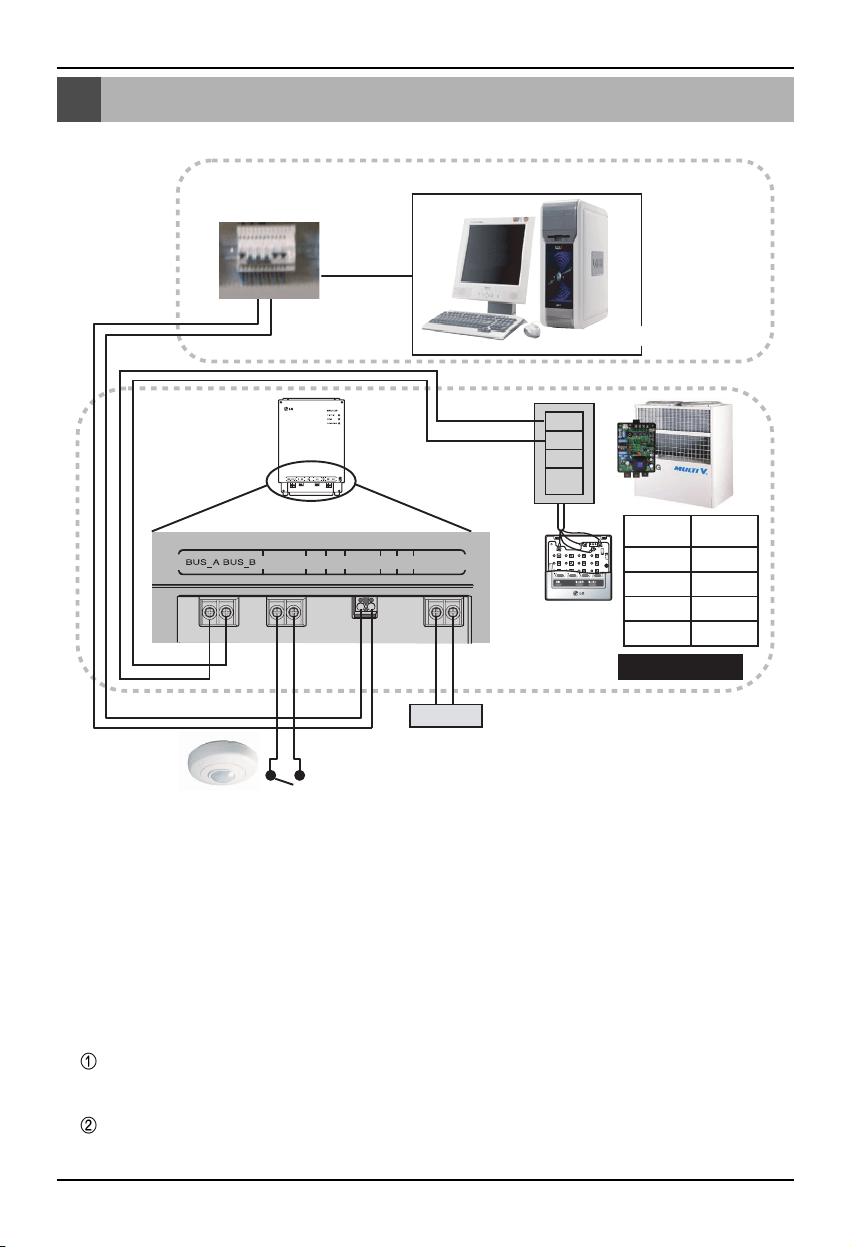
BNU-LW wiring order
12 Lonworks Gateway
BNU-LW wiring order
A
B
+10V
GND
TP/FT-10
Power
BMS Control (PC)
Fire detection sensor
(Use DC 12V or below)
F1 F2 LAN LON PWR 12V GND
PI485
terminal
Central
controller
PI485
VOC
GND
C
D
10V
GND
BUS_A
BUS_B
LG does NOT supply this section ( Connection and Installation)
LonWorks
Adaptor
LG supply
[Wiring sequence]
1. Connect 485 communication line
- Pay attention to BUS A and BUS B polarity
(Refer to the G/W manual for DIP S/W
information for 485 G/W.)
2. Connect the Lonworks communication line
(TP/FT-10)
- No polarity.
3. Power supply (Select one from No. 1 or 2)
Use DC 12V adapter
- Connect to No. 6 jack from name of each
part.
Supply DC 12V to installation site
- Connect 12V and GND to No. 7 and 8
terminals.
4. Interface with simple central controller
- Set the DIP S/W No. 2 of the simple central
controller to ON and configure the setting
according to the rotary S/W address. (Refer
to setting part when connection to simple
central controller (page 20) for details.)
5. Connect fire detection sensor
- When the signal of DC 12 or below is
transmitted in case of a fire, the indoor unit
and ventilation product that is connected to
BNU-LW will all be turned off.
Loading ...
Loading ...
Loading ...