ENGLISH ITALIANO ESPAÑOL FRANÇAIS DEUTSCH CHINESE
LG
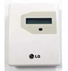
BNU-LW(Lonworks Gateway)
Installation Manual
LG
IMPORTANT
• Please read this Installation Manual carefully and
thoroughly before installing and operating your room air
conditioner.
• Please retain this Installation Manual for future reference
after reading it thoroughly.

2 Lonworks Gateway
BNU-LW (Lonworks Gateway)
TABLE OF CONTENTS
Safety Precautions.................................................................................................3
Overall system diagram.........................................................................................7
External wiring diagram ........................................................................................8
How to set the address for the central controller of the indoor unit
connected to BNU-LW (Lonworks Gateway).......................................................8
Communication line specification .......................................................................9
Name of each part................................................................................................10
Installation order..................................................................................................11
BNU-LW wiring order ...........................................................................................12
Air conditioner/ventilation function table..........................................................13
Air conditioner indoor unit function ...................................................................13
Ventilation indoor unit function..........................................................................14
BNU-LW remote diagnosis function...................................................................15
Setting method..................................................................................................15
Configuration ....................................................................................................16
Setting the indoor unit address..........................................................................18
Setting the indoor unit address .........................................................................18
Interfacing with simple central controller..........................................................19
Appendix...............................................................................................................20
A/C Objects.......................................................................................................20
Air conditioner control/monitoring point ............................................................21
Ventilation control/monitoring point...................................................................22
Network variables .............................................................................................23
Safety Precautions
Installation Manual 3
ENGLISH
Do not operate or stop
the unit by inserting or
pulling out the power
plug.
• It will cause electric shock
or fire due to heat
generation.
Ask for Product
equipment at the service
center or establishment
certainly at the specialty
store.
• It can cause an accident,
electric shock, explosion
or injury.
Use standard parts.
• Use of non standard parts
can cause electric shock,
explosion, injury,
breakdown.
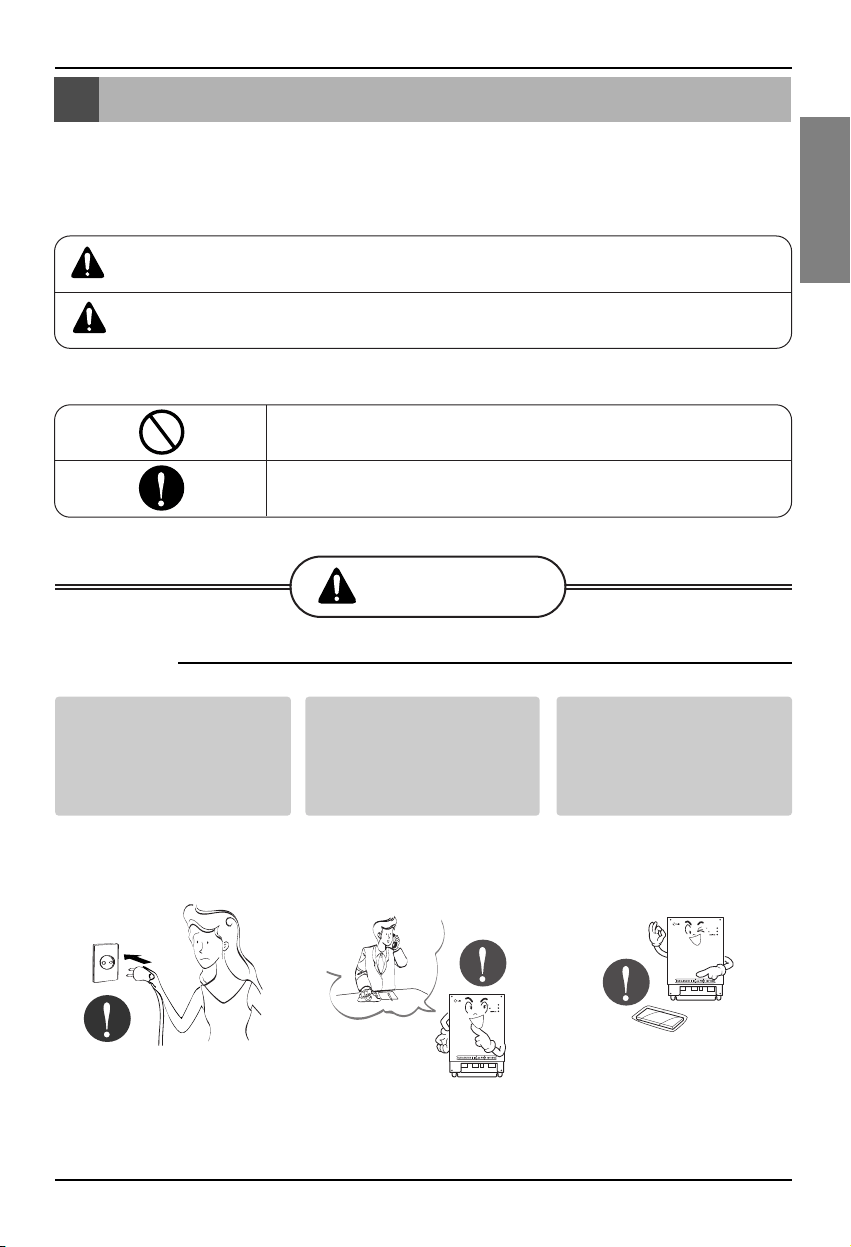
■ Operation
BNU-LW
BNU-LW
Safety Precautions
To prevent injury to the user or other people and property damage, the following instructions
must be followed.
■ Incorrect operation due to ignoring instruction will cause harm or damage. The seriousness is
classified by the following indications.
■ Meanings of symbols used in this manual are as shown below.
WARNING
CAUTION
This symbol indicates the possibility of death or serious injury.
This symbol indicates the possibility of injury or damage.
Be sure not to do.
Be sure to follow the instruction.
WARNING
Standard Parts
Safety Precautions
4 Lonworks Gateway
If water enters the product, turn the power
switch of the main body of appliance off.
• After taking the power-plug out from the
socket, contact the service center.
Keep the product away from the places
which can have moisture.
• Water may enter the unit and degrade the
insulation. It may cause an electric shock.
BNU-LW
BNU-LW
■ During usage
While re-installing the
established product, notify
the service center or
establishment specialty
store.
• It can cause an accident,
electric shock, explosion,
injury.shock.
Do not use the power cord
near Flammable gas or
combustibles, such as
gasoline, benzene, thinner,
etc.
• It may cause an explosion
or fire
Do not disjoint randomly or
repair and remodel the
product.
• It may cause fire and
electric shock
BNU-LW
BNU-LW
Wax
Thinner
BNU-LW
Do not change or extend the
conductor at random.
• It can cause fire and
electric shock.
Do not use concert with in
the octopus-like legs way.
• It can cause fire and
electric shock
Unplug the unit if strange
sounds, smell, or smoke
comes from it.
• It may cause fire and
electric shock accident.
BNU-LW
Safety Precautions
Installation Manual 5
ENGLISH
Do not put firearms near
product.
• It can cause fire.
Do not put an electric heater
or conductor near to the
product.
• It can cause fire and
electric shock.
Do not spill water inside
product.
• It can cause electric
shock and breakdown.
BNU
-LW
BNU-LW
BNU-LW
Do not place heavy goods
on wire.
• It can cause fire and
electric shock.
Hold the plug by the head of
the power plug when taking
it out.
• It may cause electric
shock and damage.
Do not place heavy goods
on product.
• It can cause product
breakdown.
BNU-LW
BNU-LW
That increase in case of
product was been flood
certainly in the service
center or establishment
specialty store commit .
• I am responsible for fire
and electric shock.
Protect the product from
handling by a children.
• It can cause accident and
product breakdown.
Do not apply shock to
product.
• I am responsible for
breakdown in case of
shock to product.
BNU-LW
BNU-LW
BNU-LW
Safety Precautions
6 Lonworks Gateway
■ During usage
CAUTION
Clean by soft hands using a
cleaning material like a soft
cloth.
• It can result in fire and
product transformation.
Do not place any live part on
the surface having water.
• It can cause product
breakdown.
Use recommended Adapter.
• Otherwise it can result in
product breakdown
BNU-LW
Wax
Thinner
BNU-LW
BNU-LW
Avoid contact to the metallic
goods such as necklace,
coin, key, a watch which
may touch the battery even
for a short-time.
• It may cause product
breakdown and injury.
Hold the plug by the head of
the power plug when taking
it out.
• It may cause electric
shock and damage.
BNU-LW
Overall system diagram
Installation Manual 7
ENGLISH
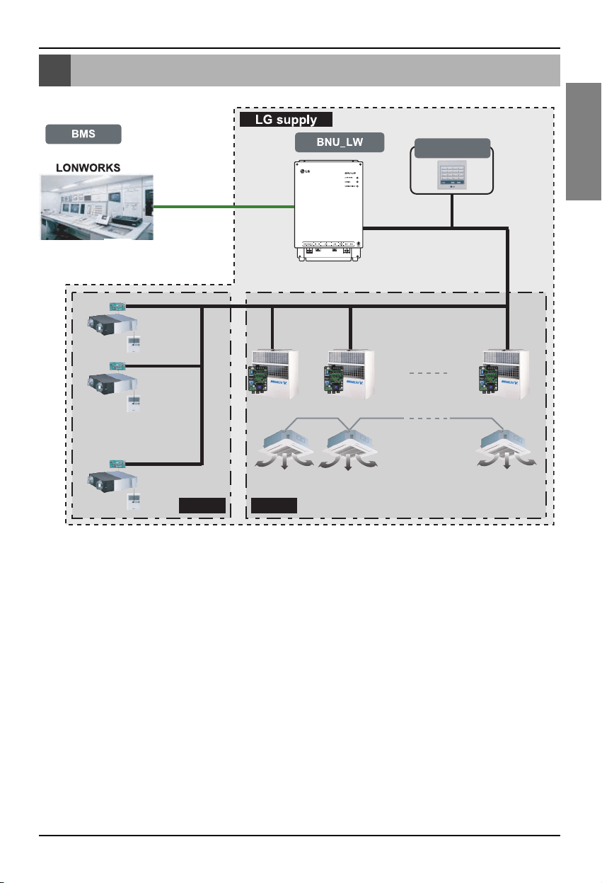
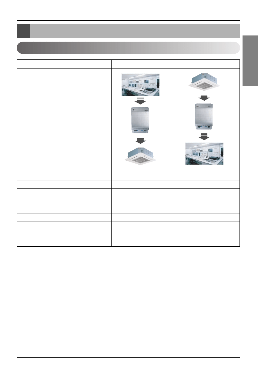
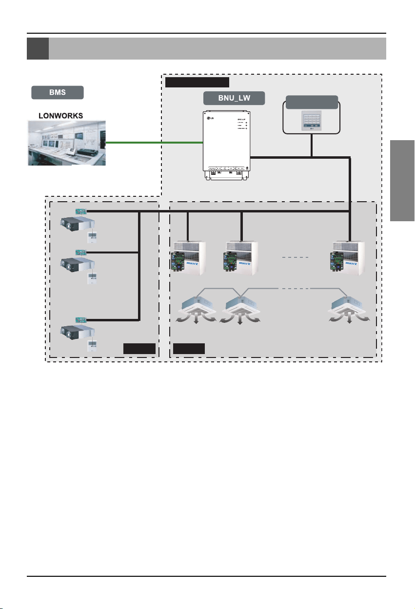
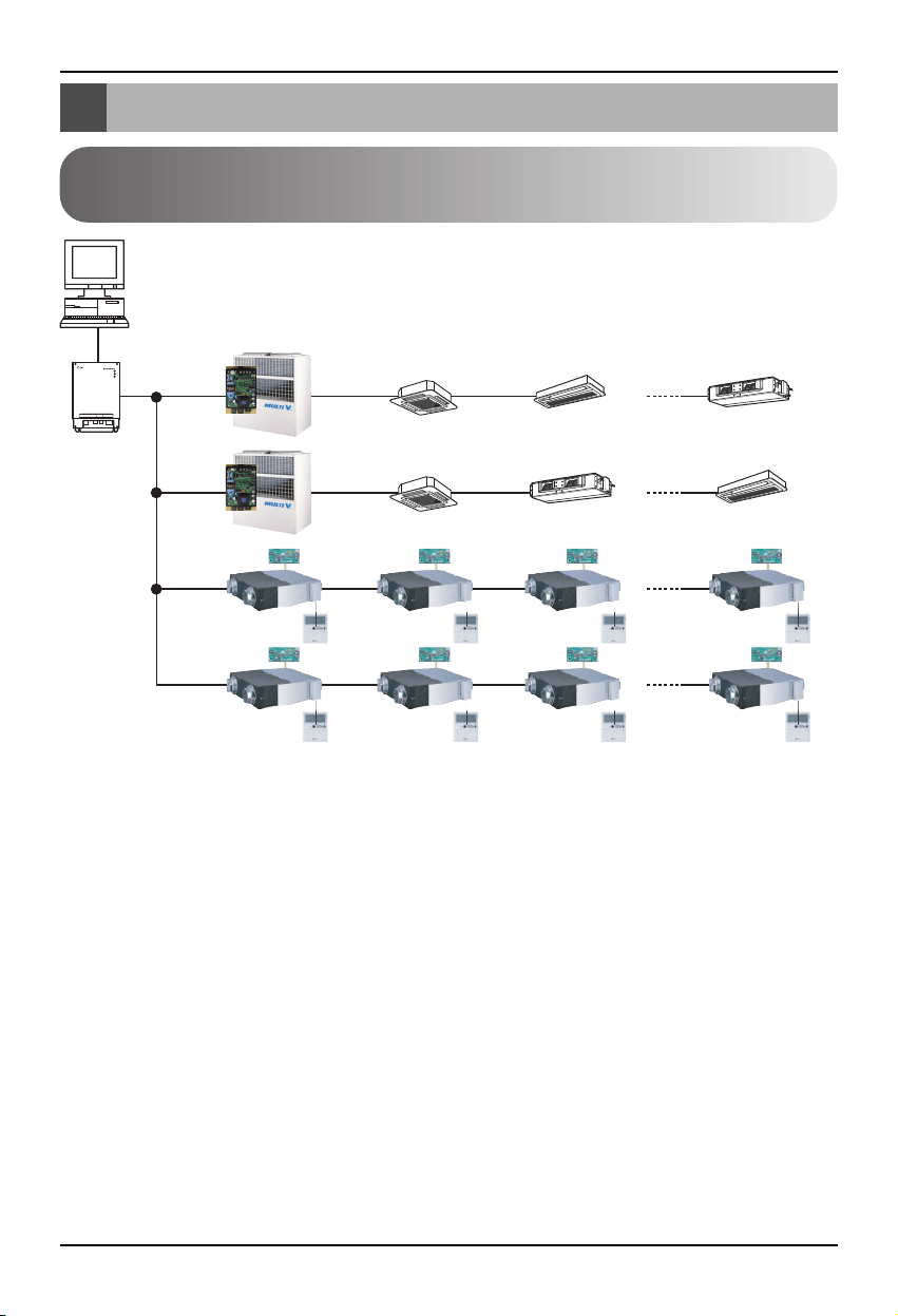
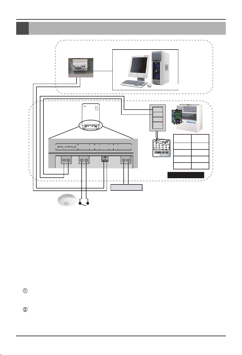
Overall system diagram
Simple central
controller
Ventilation A/C
485 communication
* Can be connected to 64 indoor units (Ventilation+Air conditioner)
* PNF-B16A1 (Lon Gateway) can be used in connection with the simple central
controller.

External wiring diagram
8 Lonworks Gateway
LON protocol
BMS system
BNU-LW
RS485
RI485 Central controller address(0.0) (0.1) ............(0.F)
Central controller address(1.0)
Central controller
address(2.0)
Central controller
address(2.4)
(2.1) (2.2) (2.3)
(2.5) (2.6) (2.7)
(1.1)............(1.F)
Air conditioner
RI485
<Maximum number of connected indoor unit: 64 units>
• When the address of the indoor unit of the air conditioner is duplicated with that of the ventilation
unit, it will not operate normally.
• Maximum of 64 units of the indoor unit (Air conditioner+Ventilation) can be connected to the BNU-
LW.
• It is recommended to connect 16 units of PI485 and maximum of d32 PI485 units to the BNU-LW.
• Ventilation products cannot be interfaced with the simple central controller.
External wiring diagram
How to set the address for the central controller of
the indoor unit connected to BNU-LW (Lonworks Gateway)
External wiring diagram
Installation Manual 9
ENGLISH
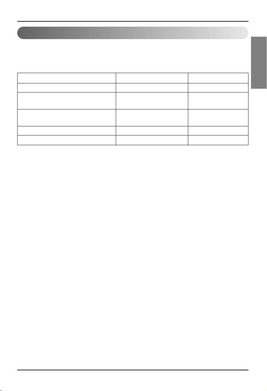
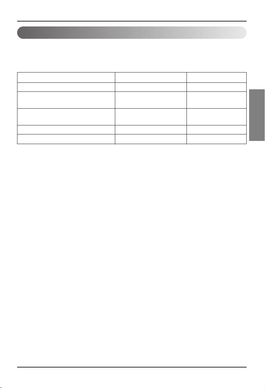
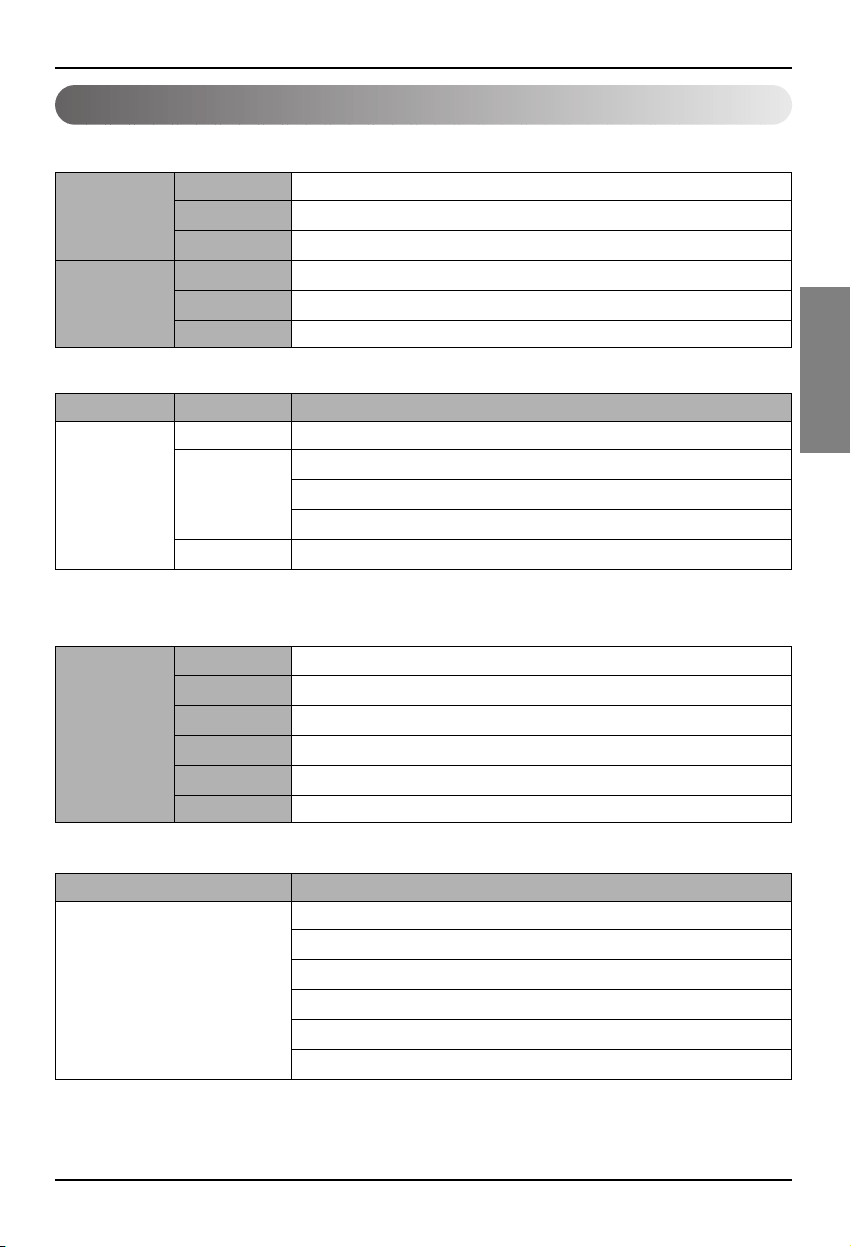
1. RS-485 communication line specification: 0.75mm
2
or above 2C shield, product to product: 200M,
total length: 1km
2. FT-10 communication line: Refer to the following table.
* Nod to node distance (max): 250m, maximum distance: 450m
* AWG: American Wire Gauge
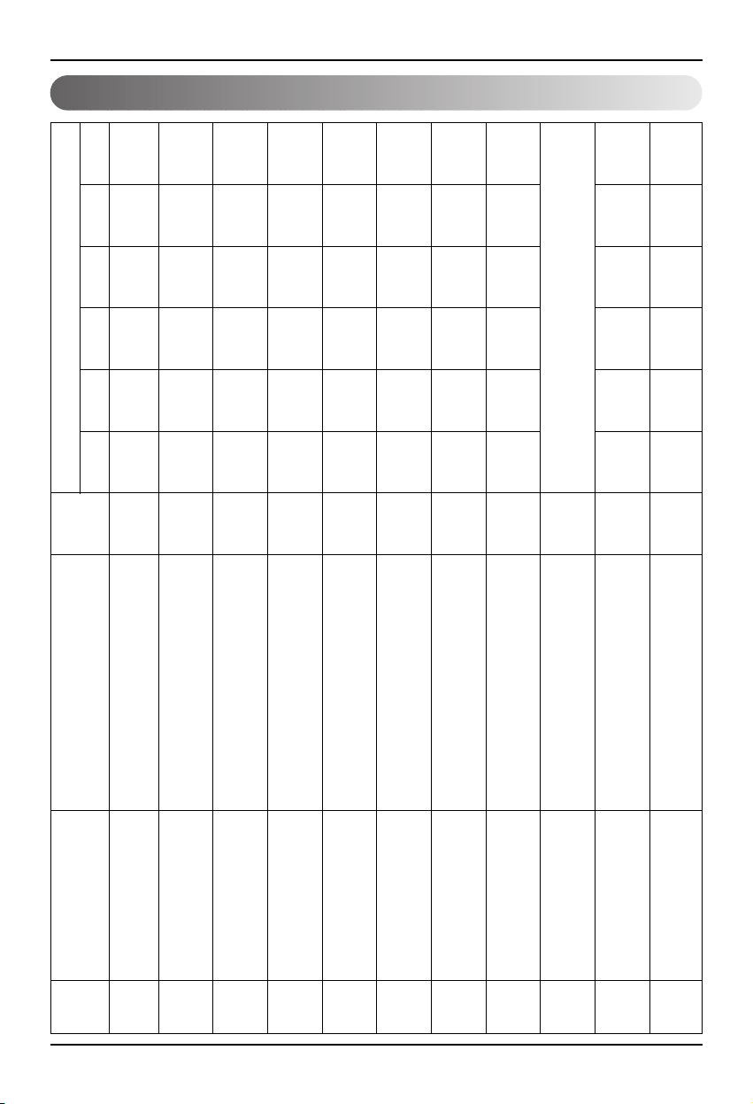
Cable Type Line thickness (AWG) Diameter
TIA 568A Category 5 cable 24 0.5mm
Belden 88471 (PVC jacket) or 16 1.3mm
equivalent cable
Belden 85102(Tefzel jacket) or 16 1.3mm
equal cable
Level IV cable 22 0.65mm
JY(st)Y 2x2x0.8 20.4 0.8mm
Communication line specification
Name of each part
10 Lonworks Gateway
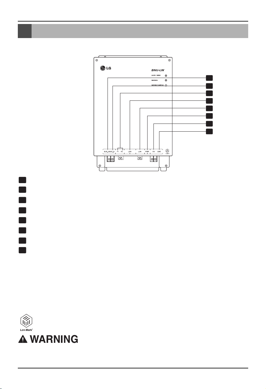
Name of each part
1
2
3
4
5
6
7
8
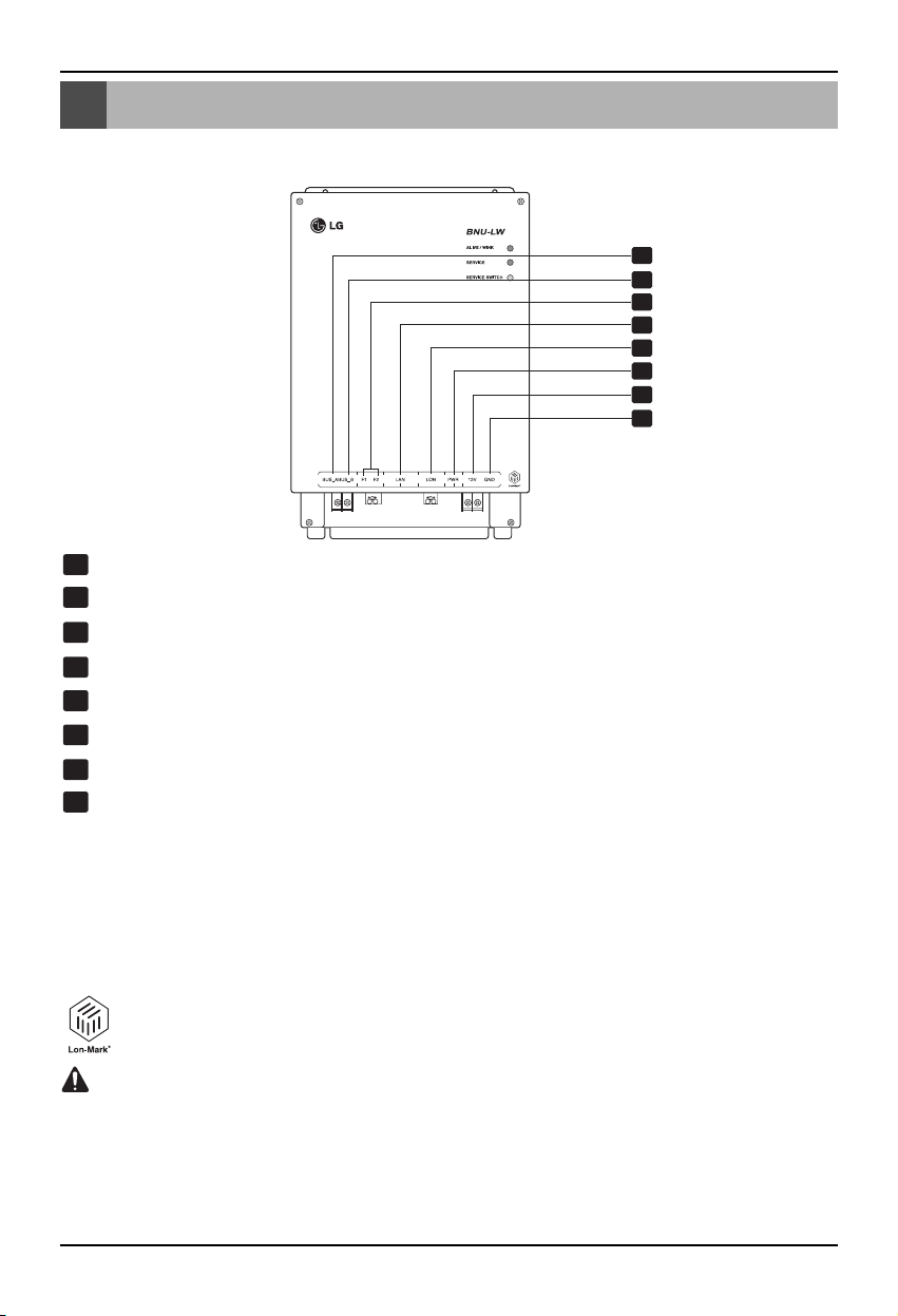
BUS_A: 485 communication line A (+)
BUS_B: 485 communication line B (-)
F1, F2: Fire detection function (external device) contact point connection
LAN: LAN port necessary for web function
LON: TP/FT-10 communication line (Lonworks system communication line) non-polarity
PWR: Connection to DC 12V power adapter
12V: Connection when not using DC 12V power adapter
GND: Connection when not using GNS adapter
ALIVE/WINK: It flashes every 1 second when it is normal
It flashes 5 times when receiving WINK command from Lonworks system
(Green)
SERVICE: It is turned off when it is normal and flashes when it is not connected to the
Lonworks system. It is turned on when the service switch is pressed.
SERVICE SWITCH: When you press the switch the Neuron ID is transmitted to the
Lonworks system, and the service LED is turned on.
BNU-LW (PNF-B16A1) product is a product certified of LON-MARK, an international
standard. (Lon Mark Version 3.3)
1
8
2
3
4
5
6
7
LONWORKS GATEWAY
No. 6 and No. 7,8 are all for power supply. Therefore, only one of two combinations should be used.
When DC 12V is used for the power, Connect No. 6 to the power (not necessary to use No. 7,8.)
When DC 12V is NOT used for the power, Connect No. 7, 8 to the power (not necessary to use No. 6.)
Installation order
Installation Manual 11
ENGLISH
Installation order
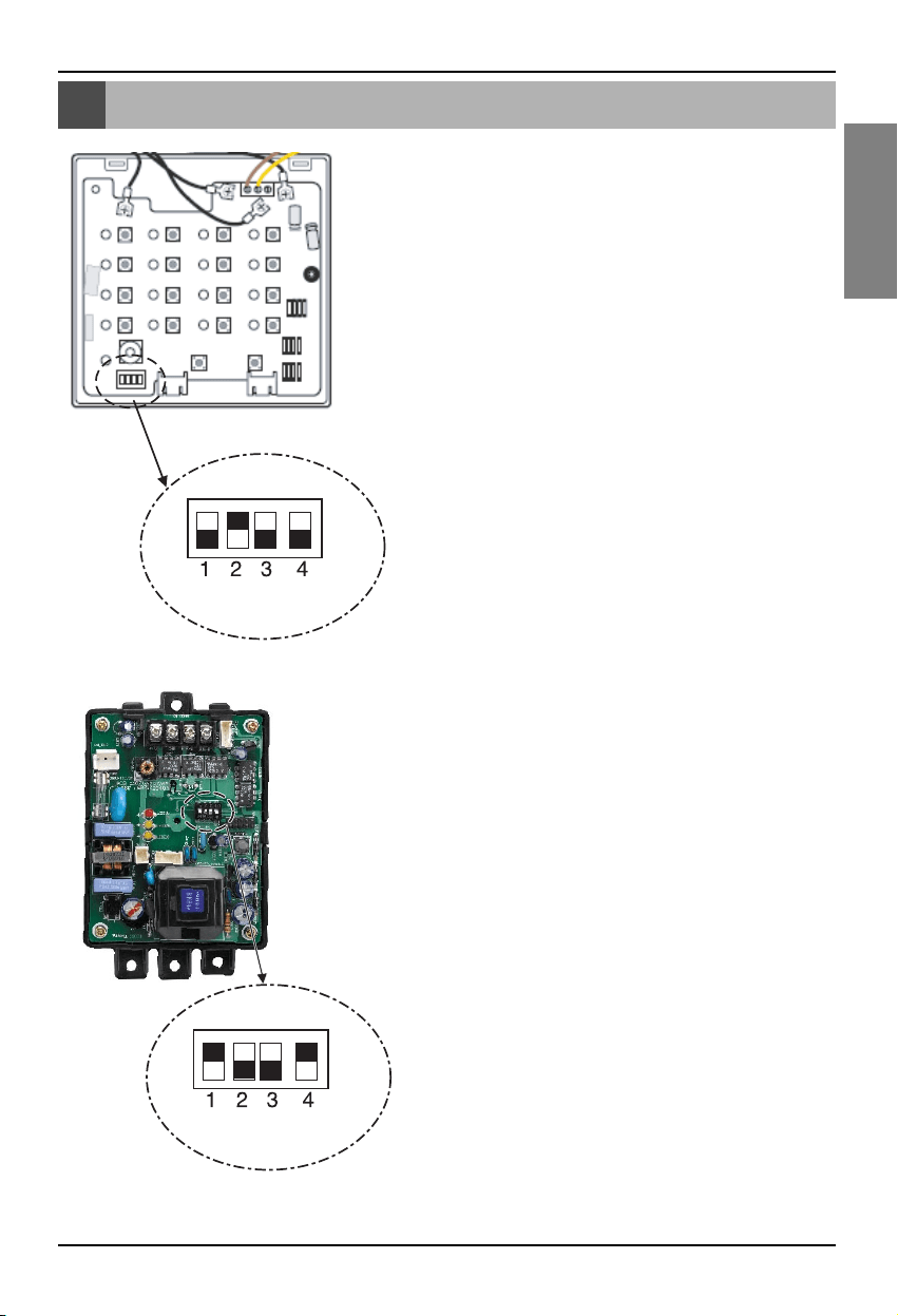
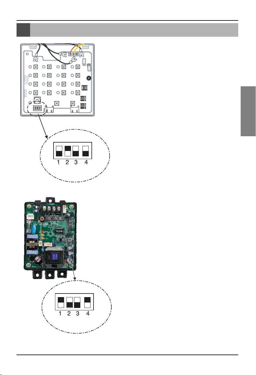
1. Install the product according to the setting of the central controller address of the indoor unit and the
DIP S/W of PI485. (Set the DIP switch No. 4 to ON.)
(Refer to the PI485 installation manual for details.)
2. Connect BUS_A and BUS_B (485 communication line) while paying attention to the connecting
polarity. (Refer to the next page.)
3. LON (TP/FT-10 line‡Lonworks Gateway communication line connection) TP/FT-10 communication
line does not have polarity. Connect the 2 communication lines to BMS.
4. PWR (Power supply)
You can select either one of the two for the power supply.
Use DC 12V power adapter
Connect to No. 6 in name of each part.
When separate DC12 can be supplied
Connect 12V and GND to No. 7 and 8 terminals.
5. When you press the service switch after connecting to the Lonworks system, the service LED is
turned on and the neuron ID is automatically transmitted to the Lonworks system.
6. Check whether the service LED is in normal condition (OFF condition) within 10 minutes. If the
service LED is in normal condition, the installation has been done normally.
7. When using the fire detection port, connect the two terminals of the fire diction sensor to F1 and F2.
(Fire detection sensor must be used for DC output of 12V or below.)
8. After the installation, connect the LAN cable between the PCs to use the web server so that you
can check whether the LG product has been installed normally. – Refer to the remote diagnosis
function part (page 16) for details.
When connecting the signal line to the terminal of Lonworks Gateway, always use a
manual driver.
(Careful attention is required not to damage the terminal block and PCB.)
BNU-LW wiring order
12 Lonworks Gateway
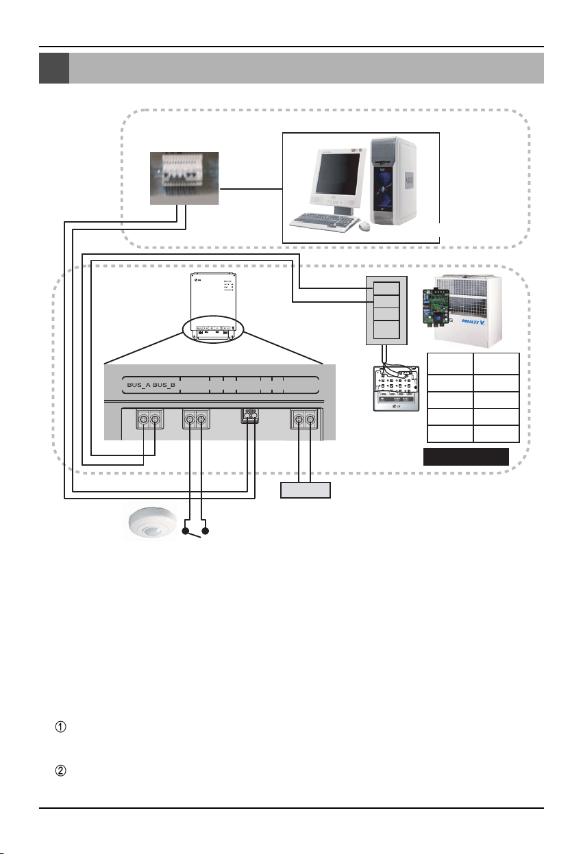
BNU-LW wiring order
A
B
+10V
GND
TP/FT-10
Power
BMS Control (PC)
Fire detection sensor
(Use DC 12V or below)
F1 F2 LAN LON PWR 12V GND
PI485
terminal
Central
controller
PI485
VOC
GND
C
D
10V
GND
BUS_A
BUS_B
LG does NOT supply this section ( Connection and Installation)
LonWorks
Adaptor
LG supply
[Wiring sequence]
1. Connect 485 communication line
- Pay attention to BUS A and BUS B polarity
(Refer to the G/W manual for DIP S/W
information for 485 G/W.)
2. Connect the Lonworks communication line
(TP/FT-10)
- No polarity.
3. Power supply (Select one from No. 1 or 2)
Use DC 12V adapter
- Connect to No. 6 jack from name of each
part.
Supply DC 12V to installation site
- Connect 12V and GND to No. 7 and 8
terminals.
4. Interface with simple central controller
- Set the DIP S/W No. 2 of the simple central
controller to ON and configure the setting
according to the rotary S/W address. (Refer
to setting part when connection to simple
central controller (page 20) for details.)
5. Connect fire detection sensor
- When the signal of DC 12 or below is
transmitted in case of a fire, the indoor unit
and ventilation product that is connected to
BNU-LW will all be turned off.
Air conditioner/ventilation function table
Installation Manual 13
ENGLISH
Air conditioner/ventilation function table
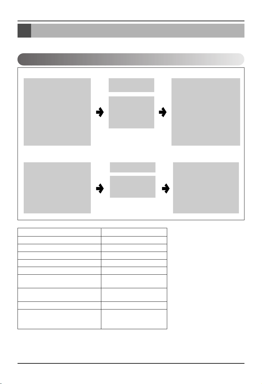
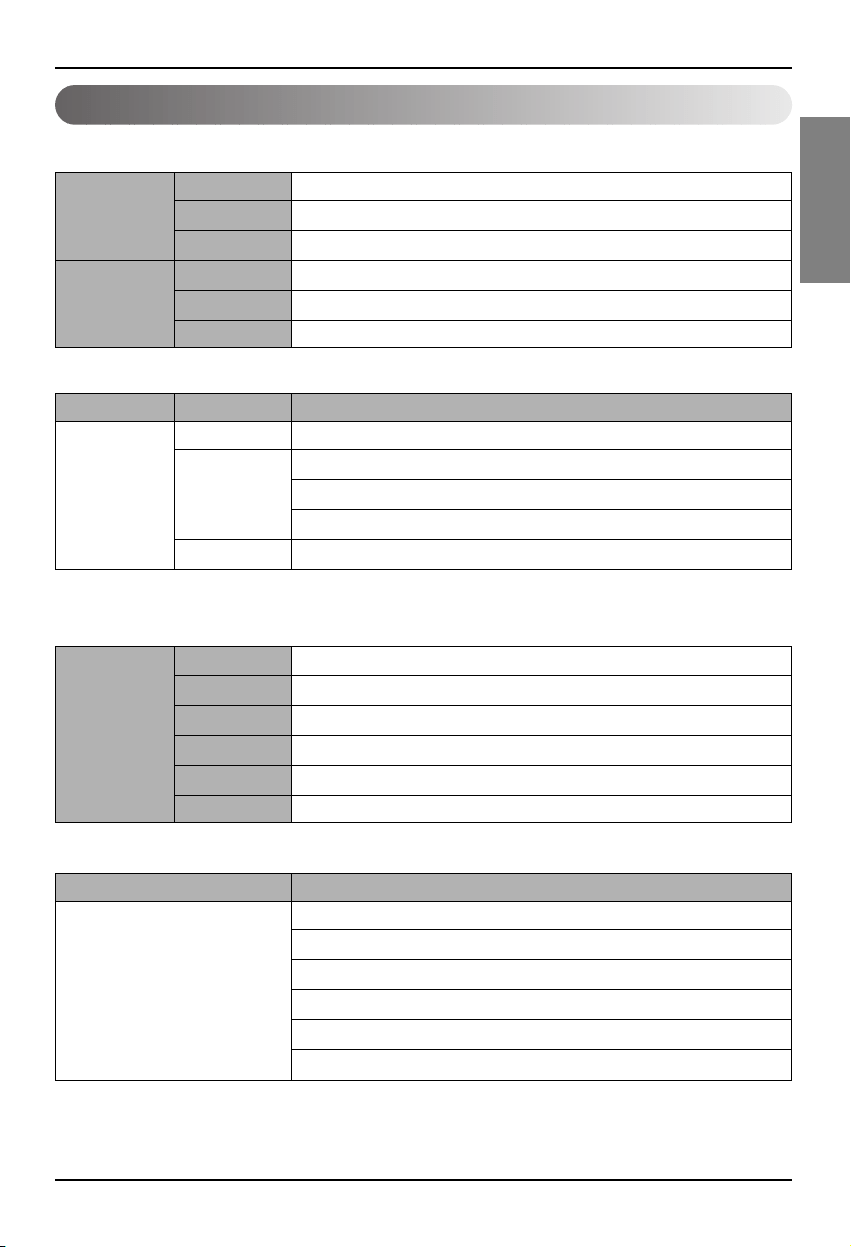
Air conditioner indoor unit function
Indoor unit individual control O O
Operating mode change O O
Fan level change O O
Temperature adjustment function O O
Lock function O O
Automatic fan direction O O
Indoor unit temperature check X O
Error check X O
Simultaneous operation/stop O X
Function
BMS
BNU-LW
Air conditioner
BMS
BNU-LW
Air conditioner
Classification Control Monitoring
Binding (connection) function: Binding function refers to the case when the output of a unit has been
bound to the input of another unit and the process of input change from
the output change. The binding function is possible with Lon unit of
other manufacturer.
Ex) When the ON/OFF output of the indoor unit No. 1 is bound to ON/OFF input of indoor unit of No. 2
and when the indoor unit No. 1 is turned on, the indoor unit No. 2 also gets turned on from
receiving the signal.

Air conditioner/ventilation function table
14 Lonworks Gateway
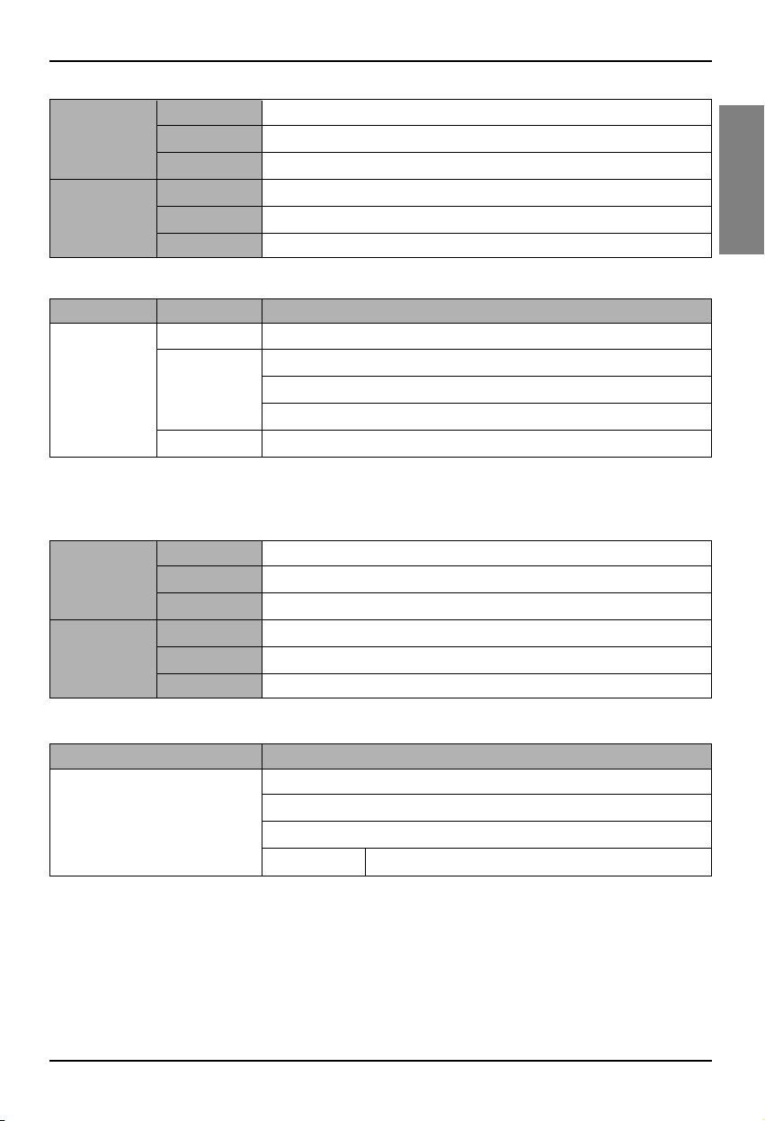
Ventilation indoor unit function
Indoor unit individual control O O
Operating mode change O O
Fan level change O O
User operation mode
OO
(Quick ventilation, power save, heating)
Lock function O O
Error check X O
Simultaneous operation/stop O X
Function
BMS
BNU-LW
Ventilation
BMS
BNU-LW
Ventilation
Classification Control Monitoring
Binding (connection) function: Binding function refers to the case when the output of a unit has been
bound to the input of another unit and the process of input change from
the output change. The binding function is possible with Lon unit of
other manufacturer.
Ex) When the ON/OFF output of the indoor unit No. 1 is bound to ON/OFF input of indoor unit of No. 2
and when the indoor unit No. 1 is turned on, the indoor unit No. 2 also gets turned on from
receiving the signal.
BNU-LW remote diagnosis function
Installation Manual 15
ENGLISH
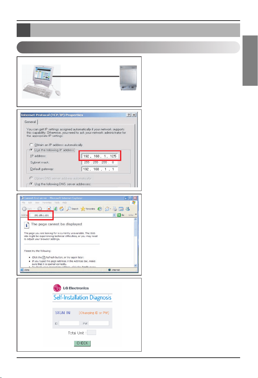
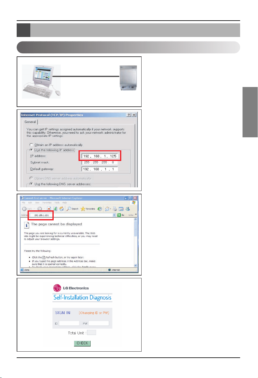
1. Connect the LAN line between the PC
and the LAN port of the BNU-LW.
2. Set the network IP of the used PC to
192.168.1.xxx (except 101).
3. Enter 192.168.1.101 in the Internet
Explorer.
4. The above picture is shown when
connected normally.
• Initial ID: lonwork
• Initial password: lonwork
• Enter the total number of connected
indoor units in the Total Unit block.
BNU-LW remote diagnosis function
Setting method
LAN(cross cable)
BNU-LW remote diagnosis function
16 Lonworks Gateway
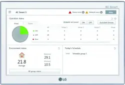
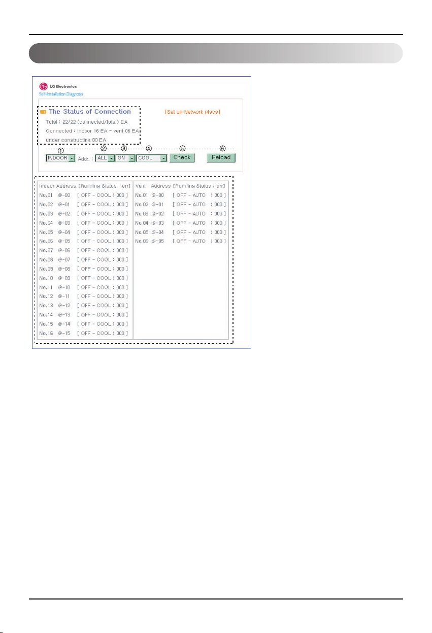
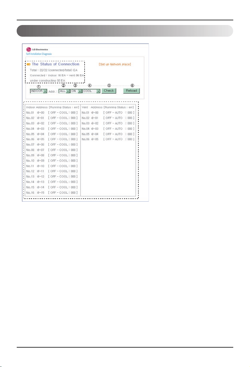
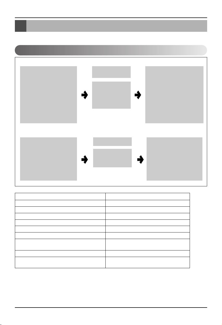
Configuration
• After entering the ID and password,
the air condition and ventilation
products currently connected are
displays as shown in the picture.
• “A” part displays the number of air
condition and ventilation products
are currently connected.
• When you would like to control a
product ➀ Select the product – ➁
Set the address – ➂ Command
ON/OFF – ➃ Select the mode – ➄
Click on check to control the
product.
• When you would like to check the
current status ➅ Click on Reload
and you will be able to check the
current indoor unit status in the “B”
part.
• When you would like to change the
IP, click on [Set up Network place]
to change the IP.
"A"
"B"
BNU-LW remote diagnosis function
Installation Manual 17
ENGLISH
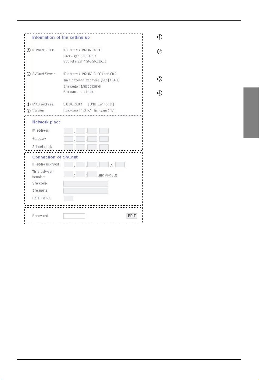
A
B
C
D
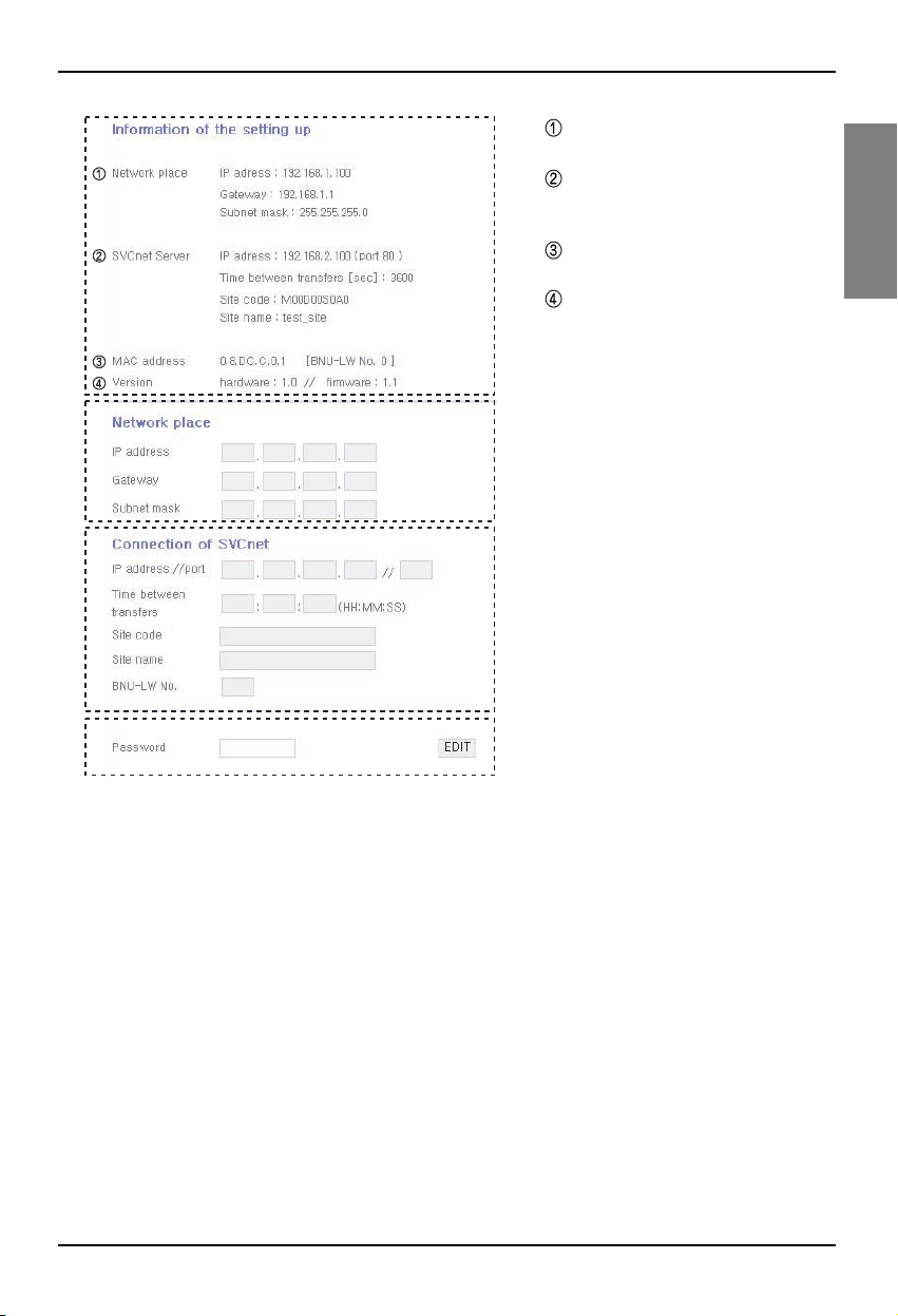
A: It displays the current IP, Gateway,
Subnet mask information.
When you would like to use the
SVCnet Server, it displays the
SVCnet Server information.
It displays the MAC address
information.
It displays the current version
information of the BNU-LW.
B: When you would like to change the IP
and Gateway, Subnet mask
information, press the Edit button next
to the information you would like to
change.
C: This is the space to enter the SVCnet
Server information to connect.
SVCnet Server is the service that
monitors the air conditioner status
connected to BNU-LW through the
LAN in the future by the LG
Electronics Service Center to provide
early notification in case of a problem.
D: In order to prevent the network or
arbitrary change, a security function
has been applied for you to enter the
initial login password to change the
network setting.
Setting the indoor unit address
18 Lonworks Gateway
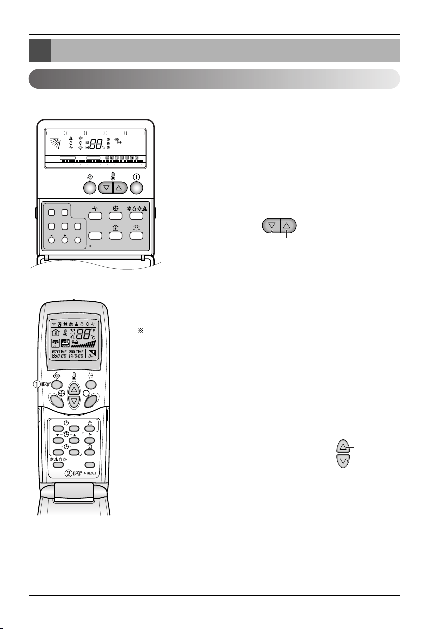
Setting the indoor unit address
Setting the indoor unit address
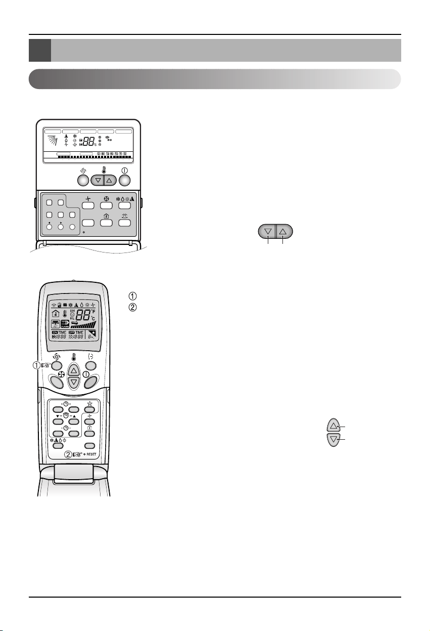
When using the wired remote controller
When using the wireless remote controller
Timer Cancel
Program Week
Hour Min
Holiday
Set/Clr
RESET
ZONE
1234
Operation unit
Humidify
JET
AUTO
AUTO SWING OPERATION
FAN SPEED
Program set
SUB FUNCTION
SET TEMP
Room Temp
HI
MED
LO
Heater
Defrost
Filter
Preheat
Out door
Time
Timer
On
Set no. Time
Off
01 03 05 07 09 11 13 15 17 19 21 23
Plasma
ON OFF
SET
CANCEL
PLASMA
Group No. Indoor unit No.
Temperature adjustment
Temperature
1. Press the week day and reservation set/cancel buttons
simultaneously for 3 seconds.
2. By using the temperature adjustment button, set the indoor unit
address.
Setting range: 00~FF
3. When you press the week day and reservation set/cancel
buttons simultaneously for 3 seconds, the address setting is
completed.
Address setting mode
1. ➀ Press the top left button for more than 3 seconds. ➁ While the top left
button pressed, press the Reset button .
The wireless remote controllers have different shapes according to
the model.
2. By using the temperature adjustment button, set the indoor unit address.
Setting range: 00~FF
3. After setting the address, press the ON/OFF button toward the indoor
unit 1 time.
4. The indoor unit will display the set address to complete the address
setting. (The address display time and method can differ by the indoor
unit type.)
5. Reset the remote controller to use the general
operation mode.
Address check mode
1. With the top right button pressed, press the Reset
button.(Press the left button for more than 3
seconds.)
2. Press the ON/OFF button toward the indoor unit 1 time, and the indoor
unit will display the set address in the display window. (The address
display time and method can differ by the indoor unit type.)
3. Reset the remote controller to use the general operation mode.
❈ The above function might not work for some remote controllers depending on the manufactured
date of the wired/wireless remote controller.
It is not relevant for the consumer use and you can set the address with a remote controller that has
the address setting functionality during the installation.
Group No.
Indoor unit No.
Temperature
adjustment
Interfacing with simple central controller
Installation Manual 19
ENGLISH
Interfacing with simple central controller
How to interface with simple central
controller
• When interfacing with simple central controller, turn the DIP
S/W No. 2 of the simple central controller ON.
• Set the rotary S/W to the group address of the indoor unit you
would like to control.
How to set PI-485
How to set PI-485
• BNU-LW uses LGAP communication protocol.
You can set the DIP S/W No. 1 and No. 4 of PI-485 ON.
Appendix
20 Lonworks Gateway
Appendix
A/C Objects
• The appendix carries information necessary for interfacing with BMS and not necessary for actual
installation.
Standard Fundtion Block
SCC(8500)FB
Indoor/
Ventilator unit
Network Varlables
SNVT
_
switch nviOnOff
SNVT
_
hvac
_
mode nviHeatCool
SNVT
_
switch nviFanSpeedcmd
SNVT
_
switch nviLock
SNVT
_
switch nviSwing
SNVT
_
switch nviSetPoint
SNVT
_
switch nviUser
SNVT
_
switch nviSpaceTemp
SNVT
_
switch nvoOnOff
SNVT
_
hvac
_
mode nvoHeatCool
SNVT
_
switch nvoFanSpeed
SNVT
_
switch nvoLock
SNVT
_
switch nvoSwing
SNVT
_
temp
_
P nvoSetPoint
SNVT
_
hvac
_
status nvoUnitStatus
SNVT
_
count nvoUser
SWITCH(3200)FB
Total
Control
SNVT
_
switch
nviTotalOnOff
_
Indoor
SNVT
_
switch
nviTotalOnOff
_
Vent
SNVT
_
switch nvoSwitch
• You can enable control and monitoring as shown in the figure for one air conditioner/ventilation unit.
• The network variable can differ from the actual.
(Refer to the XIF file for correct network variable.)
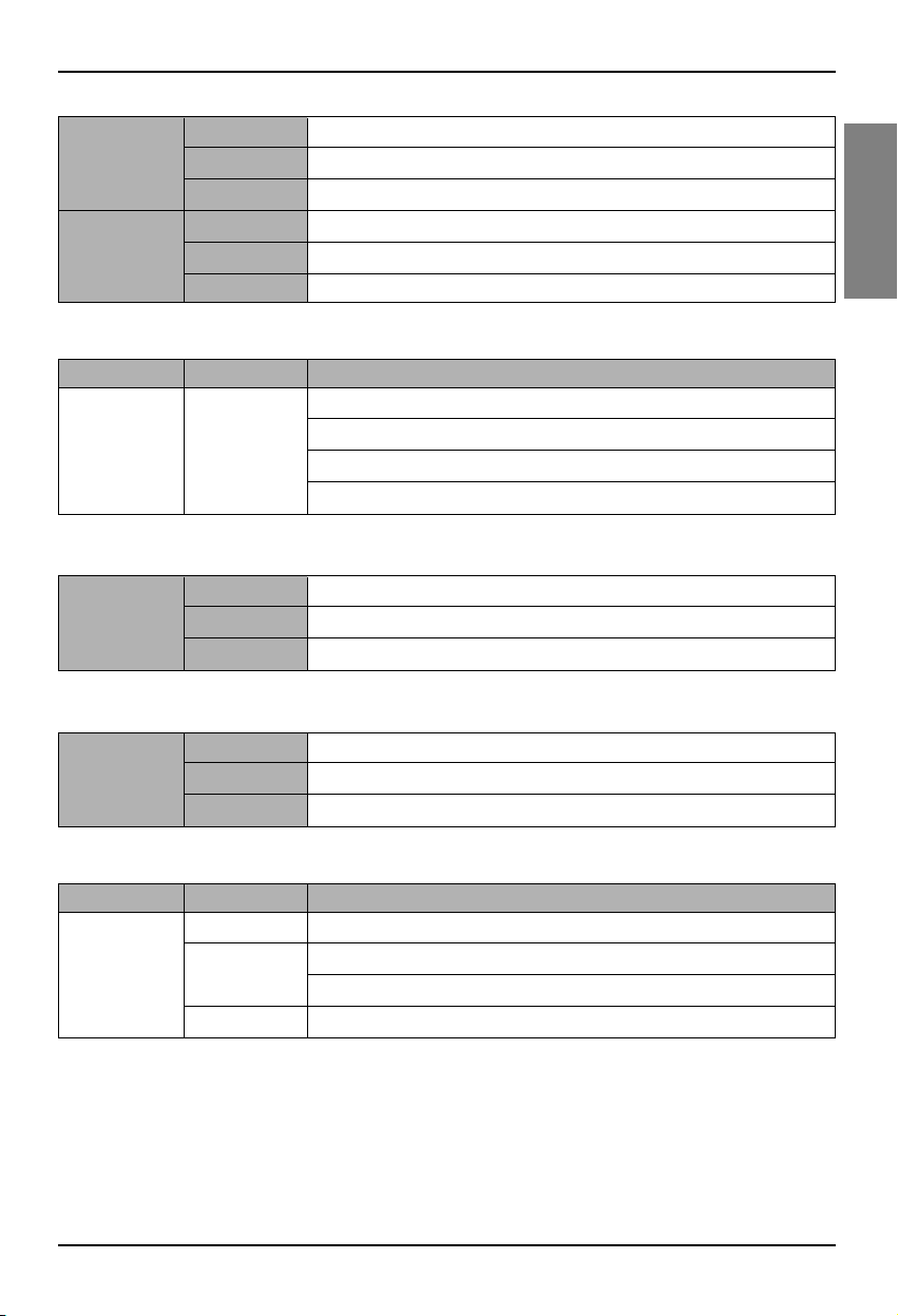
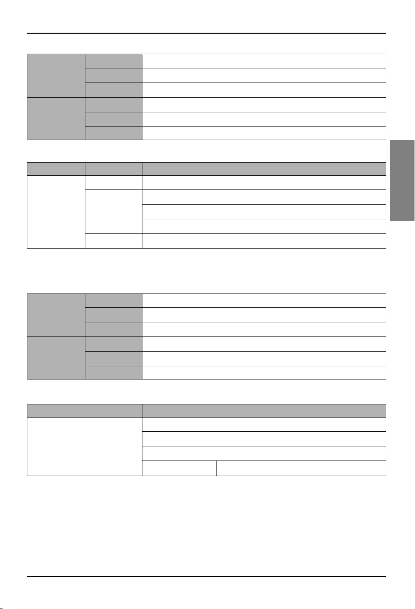
Control Monitoring
On/Off command
Mode selection command
Fan level selection command
Indoor unit lock command
Fan direction command
Temperature setting command
Ventilation additional function command
(Only applies for ventilation product)
Air conditioner total On/Off control
Ventilation total On/Off control
On/Off status monitoring
Mode status monitoring
Fan level status monitoring
Lock status monitoring
Fan direction status monitoring
Temperature setting status
monitoring
Current temperature monitoring
Error display
Ventilation additional function
status monitoring (Only applies
for ventilation product)
Appendix
Installation Manual 21
ENGLISH
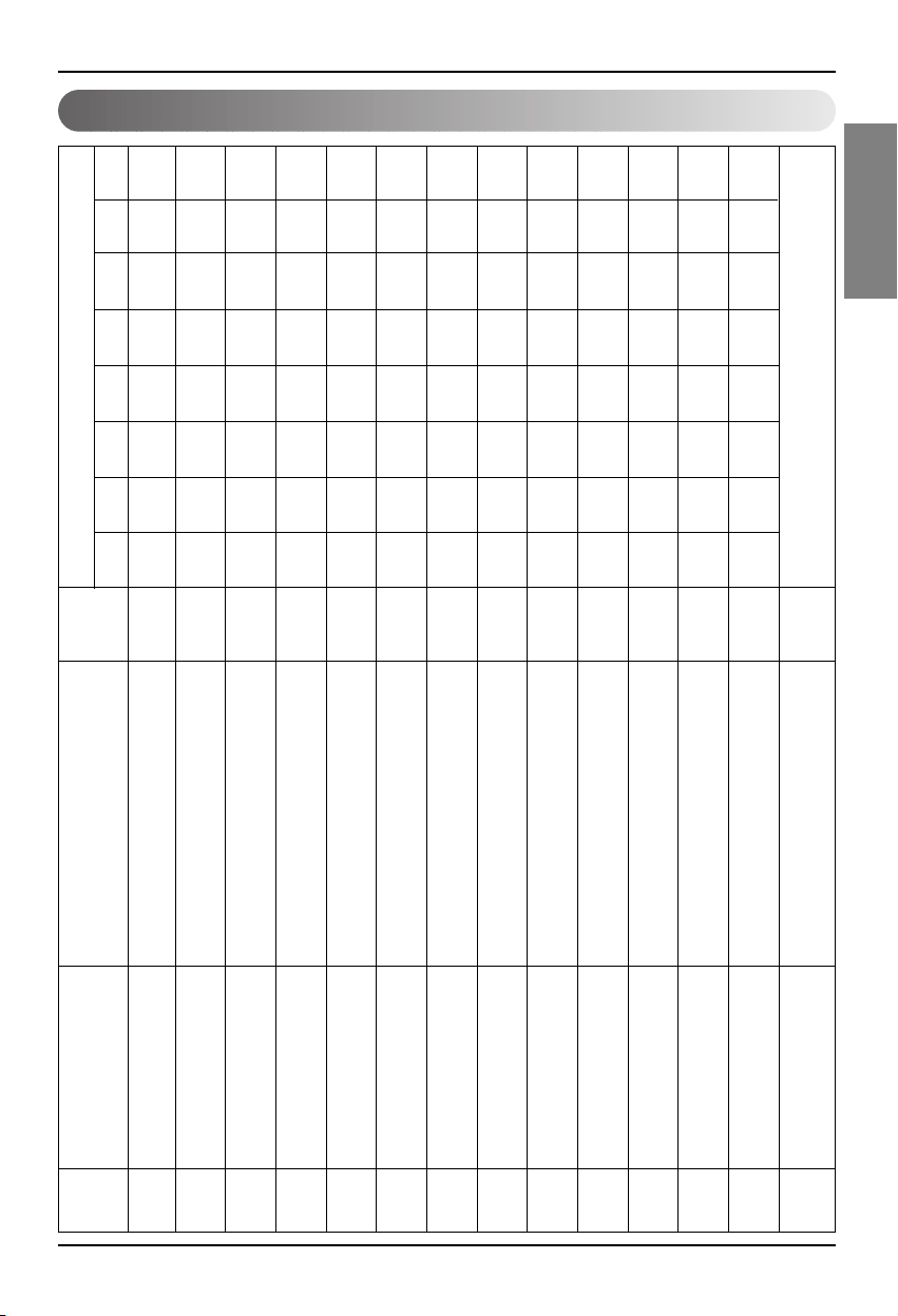
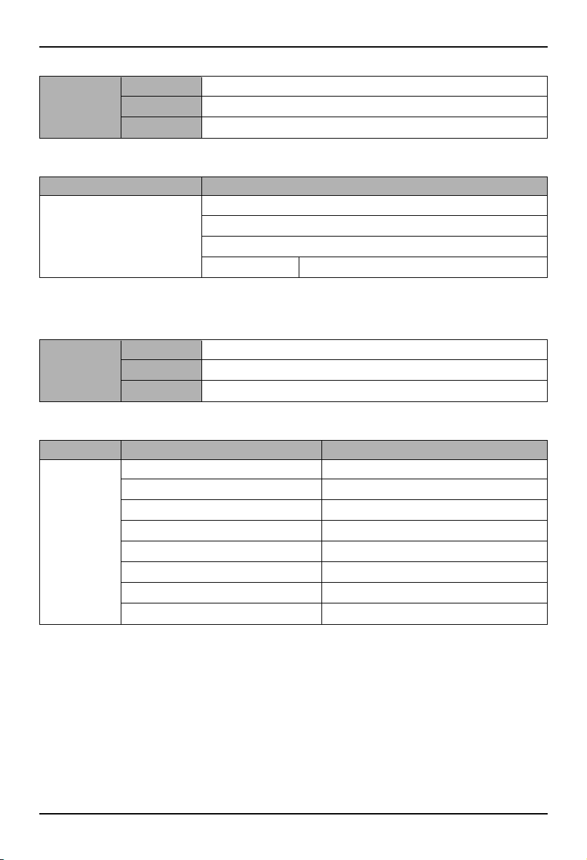
Air conditioner control/monitoring point
1 ON/OFF (setting) SNVT_switch nviOnOff_nn input Stop
Operation
2 ON/OFF (status) SNVT_switch nvoOnOff_nn output Stop
Operation
3 Lock (setting) SNVT_switch nviLock_nn input Cancel Setting
4 Lock (status) SNVT_switch nvoLock_nn output Cancel Setting
5 Operation Mode (setting) SNVT_hvac_modenviHeatCool_nn input Auto Heating Cooling Fan Dry
6 Operation Mode (status) SNVT_hvac_mode nviHeatCool_nn output Auto Heating Cooling Fan Dry
7 Swing(setting) SNVT_switch nviSwing_nn input Cancel Setting
8 Swing(status) SNVT_switch nvoSwing_nn output Cancel Setting
9 Fan speed(setting) SNVT_switch nviFanSpeedCmd_nn input Low Med High Auto
Super Low
10 Fan speed(status) SNVT_switch nvoFanSpeed_nn output Low Med High Auto
Super Low
11 Set Room Temperature SNVT_temp_p nviSetPointCmd_nn input °C
12 Set Room Temperature SNVT_temp_p nvoSetPoint_nn output °C
13 Room Temperature SNVT_temp_p nvoSpaceTemp_nn output °C
14 Error Code SNVT_hvac_status nvoUnitStatus_nn output no errorRefer to the LG Air Conditioner Error Code.
Point
No.
Name
Object
Type
Unit
code 0 code 1 code 2 code 3 code 4 code 5 code 9 code
14
Object Name
(nn: Air conditioner and ventilation
group/indoor unit address)
Appendix
22 Lonworks Gateway
Ventilation control/monitoring point
1 ON/OFF (setting) SNVT_switch nviOnOff_nn input Stop Operation
2 ON/OFF (status) SNVT_switch nvoOnOff_nn output Stop Operation
3 Lock (setting) SNVT_switch nviLock_nn input Cancel Setting
4 Lock (status) SNVT_switch nvoLock_nn output Cancel Setting
5 Operation Mode (setting) SNVT_hvac_modenviHeatCool_nn input Auto
Heat exchange
Normal
6 Operation Mode (status) SNVT_hvac_mode nviHeatCool_nn output Auto
Heat exchange
Normal
7 Fan speed(setting) SNVT_switch nviFanSpeedCmd_nn input Low High Very high
8 Fan speed(status) SNVT_switch nvoFanSpeed_nn output Low High Very high
9 Error Code SNVT_hvac_status nvoUnitStatus_nn output Refer to the LG Air Conditioner Error Code.
10 User Mode(setting) SNVT_count nviUser_nn output Quick
Power save
heat
11 User Mode(status) SNVT_count nvoUser_nn output Quick
Power save
heat
Point
No.
Name
Object
Type
Unit
code 0 code 1 code 2 code 3 code 5 code 9
Object Name
(nn: Air conditioner and ventilation
group/indoor unit address)
Appendix
Installation Manual 23
ENGLISH
Network variables
1) Individual operation/stop input/output (Air conditioner/ventilation)
Valid Range
SNVT_switch
( Index : 95 )
NV Filed Operation
Function Operation/stop input
Input Using NV Network input variable : SNVT_switch nviOnOff_n
Operation It controls the operation/stop of each product (air conditioner/ventilation)
Function Operation/stop status display
Output Using NV Network output variable : SNVT_switch nvoOnOff_n
Operation It monitors the operating status of each product (air conditioner/ventilation)
2) Operating mode input/output (Air conditioner/ventilation)
Function Operating mode command input
Input Using NV Network input variable : SNVT_hvac_mode nviHeatCool_n
Operation It controls the operating mode of each air conditioner/ventilation product.
Function Operating mode status display
Output Using NV etwork output variable : SNVT_hvac_mode nvoHeatCool_n
Operation It monitors the operating status of each air conditioner/ventilation product.
value not used (set in 0% usually)
0 = Air conditioner/ventilation product OFF
state 1 = Air conditioner/ventilation product ON
Default Value
HVAC_AUTO : 0 = AUTO mode(air conditional), Auto (ventilation)
HVAC_HEAT : 1 = Heat mode(air conditional), heat exchange(ventilation)
HVAC_COOL: 3 = Cool mode (cool)
HVAC_FAN_ONLY: 9 = Fan mode (fan) normal ventilation
HVAC_DEHUMID:14=Dry Mode (dehumidication)
Default Value
Valid Range
SNVT_hvac_mode
( Index : 108 )
NV Operation

Appendix
24 Lonworks Gateway
1: Air conditioner, ventilation low fan
2: Air condition med fan, ventilation high fan
value 3: Air condition high fan, ventilation very high fan
4: Air condition, ventilation auto fan
5. Air conditioner super low fan
state 0: Product not applied, 1: Product applied
Default Value
3) Fan level command input/output (Air conditioner/ventilation)
Valid Range
SNVT_switch
( Index : 95 )
NV Filed Operation
Function Fan level command input
Input Using NV Network input variable : SNVT_switc nviFanSpeedCmd_n
Operation It controls the fan level of each indoor unit.
Function Fan level status display
Output Using NV Network output variable : SNVT_switch nvoFanSpeed_n
Operation It monitors the fan level of each product (air conditioner/ventilation)
value not used (set in 0% usually)
0 = Air conditioner/ventilation product lock OFF
state 1 = Air conditioner/ventilation product lock ON
Default Value
4) Lock input/output (Air conditioner/ventilation)
Valid Range
SNVT_switch
( Index : 95 )
NV Filed Operation
Function Lock setting command input
Input Using NV Network input variable : SNVT_switch nviLock_n
Operation It controls the lock status of each product (air conditioner/ventilation)
Function Lock status display
Output Using NV Network output variable : SNVT_switch nvoLock_n
Operation It monitors the lock status of each product (air conditioner/ventilation)
Appendix
Installation Manual 25
ENGLISH
value not used (set in 0% usually)
0 = Fan direction fixed for air conditioner product
state 1 = Fan direction auto for air conditioner product
Default Value
5) Fan direction auto input/output (Only applies to air conditioner)
Valid Range
SNVT_switch
( Index : 95 )
NV Filed Operation
Function Fan direction auto command input
Input Using NV Network input variable : SNVT_switch nviSwing_n
Operation It controls the fan direction of each product (air conditioner/ventilation)
Function Fan direction auto status display
Output Using NV Network output variable : SNVT_switch nvoSwing_n
Operation It monitors the fan direction of each product (air conditioner/ventilation)
6) Temperature setting input/output (Only applies to air conditioner)
Function Set temperature range input
Input Using NV Network input variable : SNVT_switch nviSetPoint_n
Operation It controls the temperature setting of each product (air conditioner/ventilation)
Function Set temperature range status display
Output Using NV Network output variable : SNVT_switch nvoSetPoint_n
Operation It monitors the set temperature of each product (air conditioner/ventilation)
At Cool mode : 18 ~ 30°C
At Heat mode : 18 ~ 30°C
At Dry mode and Fan mode : Not available
Default Value
Valid Range
SNVT_switch
( Index : 95 )
NV Operation

Appendix
26 Lonworks Gateway
7) Indoor temperature status display (Only applies to air conditioner)
Function Indoor temperature status display
Output Using NV Network output variable : SNVT_switch nvoSpaceTemp_n
Operation It monitors the indoor temperature.
8) Error output (Air conditioner/ventilation)
Function Error status display
Output Using NV Network input variable : SNVT_hvac_Status nvoUnitStatus_n
Operation It monitors the error status of each product (air conditioner/ventilation)
At Cool mode : 10 ~ 40°C
At Heat mode : 10 ~ 40°C
At Dry, Fan mode : Not available
Default Value
Valid Range
SNVT_switch
( Index : 95 )
NV Operation
Mode Currently operating mode display
Heat_output_primary Not used
Heat_output_Secondary Not used
Cool_output Not used
Cool_output Not used
Econ_output Not used
fan_output Not used
In_alarm Error code display
Valid Range
SNVT_switch
( Index : 112 )
NV Filed Operation
* Refer to the Error Code table of the product manual for the error code.
Appendix
Installation Manual 27
ENGLISH
10) Total operation/stop air conditioner indoor unit
Function Total stop command input
Input Using NV Network input variable : SNVT_switch nviTotalONOFF_indoor
Operation It turns ON or OFF all the indoor units.
11) Total operation/stop ventilation indoor unit
Function Total stop command input
Input Using NV Network input variable : SNVT_switch nviTotalONOFF_indoor
Operation It turns ON or OFF all the ventilation units.
0 = Not used
value
1 = Quick mode
2 = Power save mode
3 = Heat
9) Ventilation function command (Only applies to ventilation product)
Valid Range
SNVT_count
( Index : 8 )
NV Filed Operation
Function Ventilation user operating mode input
Input Using NV Network input variable : SNVT_count nviUser_n
Operation It controls the product function of each ventilation product.
Function Ventilation user operating mode status
Output Using NV Network output variable : SNVT_count nvoUser_n
Operation It monitors the function status of each ventilation product.
value not used
state
1 = All ON indoor/Vent unit
0 = All OFF indoor/Vent unit
Default Value
Valid Range
SNVT_switch
( Index : 95 )
NV Filed Operation

Memo
28 Lonworks Gateway

ITALIANO
LG
BNU-LW(Lonworks Gateway)
LG
Importante
• Leggere per intero questo manuale
d'intallazione prima di installare il prodotto.
• Dopo aver letto interamente il manuale,
conservarlo per riferimento futuro
Manuale d'installazione

2 Lonworks Gateway
BNU-LW (Lonworks Gateway).
SOMMARIO
Precauzioni per la sicurezza .................................................................................3
Schema generale del sistema...............................................................................7
Schema del cablaggio esterno .............................................................................8
Impostazione dell’indirizzo dell’unità di controllo centrale dell’unità interna
collegata al BNU-LW (Lonworks Gateway).........................................................8
Specifiche linea di comunicazione......................................................................9
Identificazione delle parti ....................................................................................10
Sequenza di installazione....................................................................................11
Ordine di cablaggio BNU-LW ..............................................................................12
Tabella delle funzioni condizionatore/ventilazione...........................................13
Funzionamento dell’unità interna del condizionatore intern .............................13
Funzionamento unità interna di ventilazione ....................................................14
Funzionamento diagnosi remota BNU-LW ........................................................15
Metodo di impostazione....................................................................................15
Configurazione..................................................................................................16
Impostazione dell’indirizzo dell’unità interna....................................................18
Impostazione dell’indirizzo dell’unità intern.......................................................18
Interfacciamento con l’unità di controllo centrale semplice............................19
Appendice.............................................................................................................20
Oggetti A/C .......................................................................................................20
Punto di monitoraggio/controllo condizionatore................................................21
Punto di monitoraggio/controllo ventilazione ....................................................22
Punto di monitoraggio/controllo ventilazione ....................................................23
Precauzioni per la sicurezza
Manuale d'installazione 3
ITALIANO
Non avviare o arrestare
l’unità inserendo o
estraendo la spina
dell’alimentazione.
• Ciò causerà scosse
elettriche o incendio
dovuti alla generazione di
calore.
Rivolgersi al Servizio di
assistenza tecnica autorizzata
o al negozio specializzato per
informazioni sul prodotto e
sul suo utilizzo.
•
L'utilizzo improprio del
prodotto può causare
scosse elettriche, esplosioni
o lesioni personali.
Utilizzare solo
componenti standard.
• L'uso di parti diverse può
causare scosse elettriche,
esplosioni, lesioni alla
persona e guasti.
■ In funzionamento
BNU-LW
BNU-LW
Precauzioni per la sicurezza
Per evitare infortuni all'utente o a terzi e danni alla proprietà, attenersi alle seguenti istruzioni.
■ L’uso errato causato dalla mancata osservanza delle istruzioni può causare danni o lesioni.
L’importanza è classificata dalle seguenti indicazioni.
■ Il significato dei simboli utilizzati in questo manuale è spiegato di seguito.
Attenzione
Avvertenza
Questo simbolo indica la possibilità di decesso o di grave infortunio.
Questo simbolo indica il rischio di lesioni alla persona o di danni alla proprietà.
Azione/operazione da non fare.
Attenersi alle istruzioni.
Attenzione
Componenti standard

Precauzioni per la sicurezza
4 Lonworks Gateway
In caso di ingresso di acqua nel prodotto,
spegnere l’interruttore di alimentazione del
corpo principale dell’apparecchio.
• Dopo avere rimosso il cavo dalla presa,
contattare il centro di assistenza.
Tenere il prodotto lontano da ambienti
umidi.
• L'eventuale ingresso di acqua nell'unità
potrebbe deteriorarne l’isolamento. Ciò
potrebbe causare scosse elettriche.
BNU-LW
BNU-LW
■ Durante l’uso
Se è necessario reinstallare
il prodotto, informare il
centro di assistenza tecnica
o il rivenditore specializzato.
•
L'utilizzo improprio del
prodotto può causare scosse
elettriche, esplosioni o lesioni
personali.
Non utilizzare il cavo di
alimentazione in prossimità
di gas infiammabili o
combustibili, quali benzina,
benzene, solventi, ecc..
• Ciò potrebbe causare
l'insorgere di incendi o di
esplosioni.
Non smontare o riparare o
apportare modifiche al
prodotto.
•
Ciò potrebbe causare
incendi e scosse elettriche.
BNU-LW
BNU-LW
Wax
Thinner
BNU-LW
Non modificare o prolungare
il cavo di alimentazione.
• Ciò potrebbe causare
incendi e scosse
elettriche.
Non usare con cavi
intrecciati o sovrapposti.
• Ciò potrebbe causare
incendi e scosse
elettriche.
Scollegare l’unità in caso di
rumori, odori o fumo
anomali.
•
Ciò potrebbe causare
incendi e scosse elettriche.
BNU-LW
Precauzioni per la sicurezza
Manuale d'installazione 5
ITALIANO
Tenere lontano da armi da
fuoco.
• Ciò potrebbe causare
incendi.
Tenere il prodotto lontano
da riscaldatori e cavi
elettrici.
•
Ciò potrebbe causare
incendi e scosse elettriche.
Non far gocciolare acqua
all'interno dell'unità.
• Ciò potrebbe causare
scosse elettriche e guasti.
BNU
-LW
BNU-LW
BNU-LW
Non mettere oggetti pesanti
sul cavo di alimentazione.
• Ciò potrebbe causare
incendi e scosse
elettriche.
Estrarre il cavo di
alimentazione tenendolo per
la spina.
•
In caso contrario, potrebbero
verificarsi scosse elettriche o
danni al prodotto.
Non mettere oggetti pesanti
sul prodotto.
• Ciò potrebbe causare
guasti.
BNU-LW
BNU-LW
Se incautamente si versa acqua
sull'unità o se le parti interne del
prodotto si bagnano, rivolgersi
al centro di assistenza tecnica o
al rivenditore specializzato per
istruzioni in proposito.
•
Se ciò si verifica, l'utente è
responsabile del possibile verificarsi
di incendi o scosse elettriche.
Tenere il prodotto lontano
dalla portata dei bambini.
•
In caso contrario,
potrebbero verificarsi
incidenti o danni al prodotto.
Proteggere il prodotto da
forti impatti.
• L’utente è responsabile
del possibile verificarsi di
danni in caso di urto.
BNU-LW
BNU-LW
BNU-LW
Precauzioni per la sicurezza
6 Lonworks Gateway
■ Durante l’uso
Avvertenza
Pulire delicatamente usando
un panno morbido.
•
L'uso di detergenti aggressivi
potrebbe causare incendi o
alterare le caratteristiche del
prodotto.
Tenere le parti sotto
tensione lontano da acqua o
da superfici bagnate.
• Ciò potrebbe causare
guasti.
Utilizzare solo il tipo di
adattatore raccomandato.
• In caso contrario,
potrebbero verificarsi
danni al prodotto.
BNU-LW
Wax
Thinner
BNU-LW
BNU-LW
Evitare che la batteria venga
a contatto con parti in
metallo, quali collane,
monete, chiavi, orologi.
• Ciò potrebbe causare
danni al prodotto e lesioni
alla persona.
Estrarre il cavo di
alimentazione tenendolo
per la spina.
•
In caso contrario,
potrebbero verificarsi
scosse elettriche o danni al
prodotto.
BNU-LW
Schema generale del sistema
Manuale d'installazione 7
ITALIANO
Schema generale del sistema
Unità di controllo
centrale semplice
Ventilazione
A/C
Comunicazione 485
* Può essere collegato a 64 unità interne (ventilazione+condizionatore)
Fornitura LG
* Il PNF-B16A1 (Lon Gateway) può essere utilizzato congiuntamente all’unità di
controllo centrale semplice.
Schema del cablaggio esterno
8 Lonworks Gateway
Protocollo LON
Sistema BMS
BNU-LW
RS485
RI485
Indirizzo dell’unità di controllo centrale(0.0) (0.1).............(0.F)
Indirizzo dell’unità di controllo centrale(1.0)
Indirizzo dell’unità di
controllo centrale(2.0)
Indirizzo dell’unità di
controllo centrale(2.4)
(2.1) (2.2) (2.3)
(2.5) (2.6) (2.7)
(1.1).............(1.F)
Condizionatore d'aria
RI485
<Numero massimo di unità interne collegate: 64 unità>
• Quando l’indirizzo dell’unità interna del condizionatore è duplicato di quello dell’unità di ventilazione,
si hanno dei malfunzionamenti.
• Alla BNU-LW possono essere collegate massimo 64 unità dell’unità interna
(condizionatore+ventilazione).
• Si raccomanda di collegare 16 unità di PI485 e un massimo di d32 PI485 unità alla BNU-LW.
• Non è possible interfacciare i prodotti di ventilazione all’unità di controllo centrale semplice.
Schema del cablaggio esterno
Impostazione dell’indirizzo dell’unità di controllo centrale
dell’unità interna collegata al BNU-LW (Lonworks Gateway)
Schema del cablaggio esterno
Manuale d'installazione 9
ITALIANO
1. Specifica linea di comunicazione RS -485: schermo 0,75mm2 o oltre 2C, da prodotto a prodotto:
200M, lunghezza totale: 1km
2. Linea di comunicazione FT-10: fare riferimento alla tabella seguente
* Distanza da nodo a nodo (max): 250m, distanza massima: 450m
* AWG: American Wire Gauge
Tipo di cavo Spessore linea (AWG) Diametro
TIA 568A Category 5 cable 24 0.5mm
Belden 88471 (PVC jacket) or 16 1.3mm
equivalent cable
Belden 85102(Tefzel jacket) or 16 1.3mm
equal cable
Level IV cable 22 0.65mm
JY(st)Y 2x2x0.8 20.4 0.8mm
Specifiche linea di comunicazione
Identificazione delle parti
10 Lonworks Gateway
Identificazione delle parti
1
2
3
4
5
6
7
8
BUS_A: 485 linea di comunicazione A (+)
BUS_B: 485 linea di comunicazione B (-)
F1, F2: Connessione punto di contatto funzione di rilevamento incendi (dispositivo esterno)
LAN: porta LAN necessaria per funzione Web
LON: non-polarità linea di comunicazione TP/FT-10 (linea di comunicazione sistema Lonworks)
PWR: collegamento ad adattatore di alimentazione CC 12V
12V: collegamento quando non si utilizza l’adattatore CC 12V
GND: collegamento quando non si utilizza l’adattatore GNS
ALIVE/WINK: lampeggia ogni secondo quando è normale lampeggia 5 volte alla
ricezione del comando WINK dal sistema Lonworks (verde)
SERVIZIO: spento quando è normale e lampeggiante quando non collegato al sistema
Lonworks. Acceso quando viene premuto l’interruttore di servizio.
INTERRUTTORE DI SERVIZIO: quando si preme l’interruttore, l’ID Neuron viene
trasmesso al sistema Lonworks e il LED di servizio si accende.
Il prodotto BNU-LW (PNF-B16A1) è certificato LON-MARK, uno standard
internazionale(Lon Mark versione 3.3).
1
8
2
3
4
5
6
7
Gateway Lonworks
No. 6 e No. 7, 8 sono tutti riservati all'alimentazione. Quindi, solo una delle due
combinazioni dovrebbe essere usata.
Se si usa DC 12V come alimentazione, connettere No. 6 all'alimentazione (non è
necessario usare No. 7 e No. 8)
Quando NON si usa DC 12V per l'alimentazione, connettere No. 7 e No. 8
all'alimentazione (non è necessario usare No. 6)
Attenzione
Sequenza di installazione
Manuale d'installazione 11
ITALIANO
Sequenza di installazione
1. Installare il prodotto secondo l’impostazione dell‘indirizzo del controller centrale dell’unità interna e
del DIP S/W di PI485. (Impostare il DIP switch n. 4 su ON.)
(Fare riferimento al manuale di installazione del PI485 per maggiori dettagli.)
2. Collegare BUS_A e BUS_B (linea di comunicazione 485) facendo attenzione alla polarità di
connessione. (Fare riferimento alla pagina successiva.)
3. LON (Linea TP/FT-10 ‡connessione linea di comunicazione Lonworks Gateway) la linea di
comunicazione TP/FT-10 è priva di polarità.
Connettere le 2 linee di comunicazione al BMS.
4. PWR (alimentazione)
Si può selezionare una delle due per l’alimentazione.
Utilizzare l’adattatore di alimentazione CC 12V
Connettere al n.6 in identificazione delle parti.
In caso di separazione alimentare CC12
Collegare 12V e GND ai terminali n. 7 e 8.
5. Se si preme l’interruttore di servizio dopo aver collegato il sistema Lonworks, si accende il LED di
servizio e l’ID neuron viene trasmesso automaticamente al sistema Lonworks.
6. Accertarsi che il LED di servizio si trovi in condizioni normali (OFF) entro 10 minuti. Se il LED di
servizio si trova in condizioni normali, l’installazione è stata eseguita correttamente.
7. Se si utilizza la porta di rilevamento incendio, collegare i due terminali del sensore di rilevamento
incendio su F1 e F2.
(Il sensore di rilevamento incendio deve essere utilizzato per l’uscita CC di 12V o inferiore.)
8. Dopo l’installazione collegare il cavo LAN tra i PC per utilizzare il server web che permette di
verificare la corretta installazione del prodotto LG. – Fare riferimento al capitolo sul funzionamento
della diagnosi remota (pagina 16) per maggiori dettagli.
Quando si effettua il collegamento della linea di segnale al terminale di Lonworks
Gateway, utilizzare sempre un cacciavite.
(Prestare estrema attenzione a non danneggiare la morsettiera e la PCB).
Avvertenza
Ordine di cablaggio BNU-LW
12 Lonworks Gateway
Ordine di cablaggio BNU-LW
A
B
+10V
GND
TP/FT-10
Adattatore
LonWorks
Alimentazione
Controllo BMS (PC)
Sensore di rilevamento incendio
(Utilizzare CC 12V o inferiore)
F1 F2 LAN LON PWR 12V GND
PI485
terminale
Controller
centrale
PI485
VOC
GND
C
D
10V
GND
BUS_A
BUS_B
Fomltura LG
LG non fornisce questa sezione (connessione e installazione)
[Ordine di cablaggio]
1. Collegare la linea di comunicazione 485
- Prestare attenzione alla polarità del BUS A e
del BUS B(Fare riferimento al manuale GW
per maggiori informazioni DIP S/W per 485
G/W.)
2. Collegare la linea di comunicazione Lonworks
(TP/FT-10)
- Assenza di polarità
3. Alimentazione (selezionare tra n.1 o 2)
Utilizzare l’adattatore di CC 12V
- Collegare la jack n. 6 dall’identificazione
di ogni parte.
Alimentare CC 12V per il luogo di
installazione
- Collegare 12V e GND ai terminali n. 7 e
8.
4. Interfaccia con l’unità di controllo centrale
semplice
- Impostare il DIP S/W n. 2 dell’unità di
controllo centrale semplice su ON e
configurare l’impostazione all’indirizzo del
S/W a rotazione.(Fare riferimento al capitolo
sull’impostazione durante il collegamento
dell’unità di controllo centrale (pagina 20) per
maggiori dettagli).
5. Collegamento del sensore di rilevamento
incendio
- Se in caso di incendio viene trasmesso il
segnale di CC 12 o inferiore, l’unità interna e
la ventilazione collegata al BNU-LW viene
spenta.
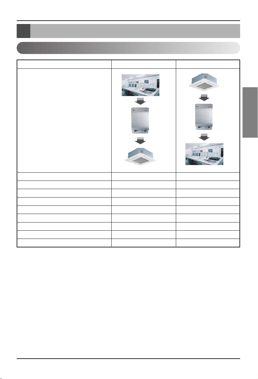
Tabella delle funzioni condizionatore/ventilazione
Manuale d'installazione 13
ITALIANO
Tabella delle funzioni condizionatore/ventilazione
Funzionamento dell’unità interna del condizionatore interno
Controllo individuale unità interna O O
Cambio modalità di funzionamento O O
Cambio potenza ventilatore O O
Funzione di regolazione della temperatura
OO
Funzione di blocco O O
Direzione automatica del ventilatore O O
Controllo temperatura unità interna X O
Controllo errore X O
Funzionamento/arresto simultaneo O X
Funzione
BMS
BNU-LW
Air conditioner
BMS
BNU-LW
Air conditioner
Classificazione Controllo Monitoraggio
Funzione di collegamento (connessione): La funzione di collegamento si riferisce al caso in cui
l’output di una unità è stato collegato all’input di un’altra
unità ed il processo di input dipende dal cambio di output.
La funzione di collegamento è possibile con unità Lon di altri
produttori.
Es) Se l’output ON/OFF dell’unità interna n.1 è collegato all’input ON/OFF dell’unità interna n.2 e si
accende l’unità interna n.1, anche l’unità interna n. 2 si accende perchè riceve il segnale.

Tabella delle funzioni condizionatore/ventilazione
14 Lonworks Gateway
Funzionamento unità interna di ventilazione
Controllo individuale unità interna O O
Cambio modalità di funzionamento O O
Cambio potenza ventilatore O O
Modalità di funzionamento utente (ventilazione
OO
rapida,
rapida, risparmio energetico, riscaldamento)
Funzione di blocco O O
Controllo errore X O
Funzionamento/arresto simultaneo O X
Funzione
BMS
BNU-LW
Ventilation
BMS
BNU-LW
Ventilation
Classificazione Controllo Monitoraggio
Funzione di collegamento (connessione): La funzione di collegamento si riferisce al caso in cui
l’output di una unità è stato collegato all’input di un’altra
unità ed il processo di input dipende dal cambio di output.
La funzione di collegamento è possibile con unità Lon di altri
produttori.
Es) Se l’output ON/OFF dell’unità interna n.1 è collegato all’input ON/OFF dell’unità interna n.2 e si
accende l’unità interna n.1, anche l’unità interna n. 2 si accende perchè riceve il segnale.
Funzionamento diagnosi remota BNU-LW
Manuale d'installazione 15
ITALIANO
1. Collegare la linea LAN tra il PC e la
porta LAN del BNU-LW.
2. Impostare l’IP di rete del PC in uso
su 192.168.1.xxx (tranne 101).
3. Immettere 192.168.1.101 in Internet
Explorer.
4. Se la connessione è corretta appare
l’immagine precedente.
• ID iniziale: lonwork
• Password iniziale: lonwork
• Immettere il numero totale di unità
interne collegate nel blocco unità
totale.
Funzionamento diagnosi remota BNU-LW
Metodo di impostazione
LAN(cross cable)
Funzionamento diagnosi remota BNU-LW
16 Lonworks Gateway
Configurazione
- Dopo aver inserito l’ID e la
password i condizionatori d’aria ed i
prodotti di ventilazione attualmente
collegati vengono visualizzati come
illustrato nell’immagine.
- La parte “A” mostra il numero di
condizionatori d’aria e prodotti di
ventilazione attualmente collegati.
- Se si desidera controllare un
prodotto ➀ Selezionare il prodotto –
➁ Impostare l’indirizzo – ➂
Accendere o spegnere (ON/OFF) –
➃ Selezionare la modalità – ➄ Fare
clic su verifica per controllo del
prodotto.
- Se si desidera controllare lo stato
corrente ➅ Fare clic su Reload per
poter controllare lo stato attuale
dell’unità interna nella parte “B”.
- Se si desidera modificare l’IP, fare
clic su [Set up Network place] per
modificare l’IP.
"A"
"B"
Funzionamento diagnosi remota BNU-LW
Manuale d'installazione 17
ITALIANO
A
B
C
D
A: Mostra l’IP corrente, il gateway, le
informazioni sulla subnet mask.
Se si desidera utilizzare il server
SVCnet Server, vengono
visualizzate le informazioni sul
Server SVCnet.
Mostra le informazioni sull’indirizzo
MAC.
Visualizza le informazioni sulla
versione corrente di BNU-LW.
B: Se si desidera cambiare l’IP, il
gateway, le informazioni sulla subnet
mask premere il pulsante Edit accanto
alle informazioni che si desidera
modificare.
C: Questo è lo spazio per immettere le
informazione del server SVCnet per
collegarsi.
Il server SVCnet è il servizio che
permette di monitorare in futuro lo
stato del condizionatore d’aria
collegato al BNU_LW attraverso la
LAN dal centro di assistenza LG
Electronics per fornire informazioni
tempestive in caso di problemi.
D: Per impedire alla rete una modifica
arbitraria, è stata impostata una
funzione di sicurezza che consente di
modificare le impostazioni di rete dopo
aver digitato la password di accesso
iniziale.
Impostazione dell’indirizzo dell’unità interna
18 Lonworks Gateway
Impostazione dell’indirizzo dell’unità interna
Impostazione dell’indirizzo dell’unità interna
Se si utilizza il telecomando cablato
Se si utilizza il telecomando senza fili
Timer Cancel
Program Week
Hour Min
Holiday
Set/Clr
RESET
ZONE
1234
Operation unit
Humidify
JET
AUTO
AUTO SWING OPERATION
FAN SPEED
Program set
SUB FUNCTION
SET TEMP
Room Temp
HI
MED
LO
Heater
Defrost
Filter
Preheat
Out door
Time
Timer
On
Set no. Time
Off
01 03 05 07 09 11 13 15 17 19 21 23
Plasma
ON OFF
SET
CANCEL
PLASMA
N°. gruppo N°. unità interna
Regolazione della temperatura
1. Premere contemporaneamente i pulsanti del giorno della
settimana e imposta/annulla programmazione per 3 secondi.
2. Utilizzando il pulsante della regolazione della temperatura,
impostare l’indirizzo dell’unità interna.
Intervallo di impostazione: 00~FF
3. Quando si premono contemporaneamente i pulsanti del giorno
della settimana e di imposta/annulla programmazione,
l’impostazione dell’indirizzo è completata.
Modalità di impostazione indirizzo
1.
Premere il tasto sinistro per un periodo superiore a 3 secondi
Con il tasto sinistro superiore premuto, premere il pulsante di ripristino.
❈ I telecomandi wireless hanno forme diverse secondo il modello.
2. Utilizzando il pulsante della regolazione della temperatura, impostare
l’indirizzo dell’unità interna.
Intervallo di impostazione: 00~FF
3. Dopo aver impostato l’indirizzo premere il pulsante ON/OFF verso l’unità
interna 1 volta.
4. L’unità interna visualizzerà l’indirizzo impostato per completarne
l’impostazione. (Il tempo di visualizzazione dell’indirizzo ed il metodo sono
diversi a seconda del tipo di unità interna.)
5. Ripristinare il telecomando per utilizzare la
modalità di funzionamento generale.
Modalità controllo indirizzo
1. Premendo il pulsante in alto a destra, premere il
pulsante Reset.(Premere il pulsante a sinistra per oltre 3 secondi.)
2. Premere il pulsante ON/OFF verso l’unità interna 1 volta. Quest’ultima
visualizzerà l’indirizzo impostato nella finestra del display. (Il tempo di
visualizzazione dell’indirizzo ed il metodo sono diversi a seconda del tipo di
unità interna.)
3. Ripristinare il telecomando per utilizzare la modalità di funzionamento
generale.
❈ La funzione di cui sopra potrebbe non funzionare con alcuni telecomandi a seconda della data di
fabbricazione e del tipo di telecomando cablato/senza fili.
Non si tratta di una condizione fondamentale in quanto l’utente può impostare l’indirizzo con un
telecomando che svolge le funzioni di impostazione di indirizzo durante l’installazione.
N°. gruppo
N°. unità interna
Regolazione
della temperatura
Interfacciamento con l’unità di controllo centrale semplice
Manuale d'installazione 19
ITALIANO
Interfacciamento con l’unità di controllo centrale semplice
Come avviene l’interfacciamento con
l’unità di controllo centrale semplice
• Nell’interfacciamento con l’unità di controllo centrale
semplice, spostare su ON il DIP S/W n. 2 dell’unità di
controllo centrale semplice.
• Impostare lo S/W rotante sull’indirizzo di gruppo dell’unità
interna che si desidera controllare.
Impostazione di PI-485
Impostazione di PI-485
• BNU-LW us ail protocollo di comunicazione LGAP.
Si può impostare il DIP S/W n. 1 e n. 4 di PI-485 su ON.
Appendice
20 Lonworks Gateway
Appendice
Oggetti A/C
• Nell’appendice sono riportate le informazioni necessarie per l’interfacciamento con BMS ma non
essenziali per l’installazione effettiva.
Blocco funzioni standard
SCC(8500)FB
Indoor/
Ventilator unit
Network Varlables
SNVT
_
switch nviOnOff
SNVT
_
hvac
_
mode nviHeatCool
SNVT
_
switch nviFanSpeedcmd
SNVT
_
switch nviLock
SNVT
_
switch nviSwing
SNVT
_
switch nviSetPoint
SNVT
_
switch nviUser
SNVT
_
switch nviSpaceTemp
SNVT
_
switch nvoOnOff
SNVT
_
hvac
_
mode nvoHeatCool
SNVT
_
switch nvoFanSpeed
SNVT
_
switch nvoLock
SNVT
_
switch nvoSwing
SNVT
_
temp
_
P nvoSetPoint
SNVT
_
hvac
_
status nvoUnitStatus
SNVT
_
count nvoUser
SWITCH(3200)FB
Controllo
totale
SNVT
_
switch
nviTotalOnOff
_
Indoor
SNVT
_
switch
nviTotalOnOff
_
Vent
SNVT
_
switch nvoSwitch
• Si può abilitare il comando ed il monitoraggio come illustrato nella figura per un condizionatore
d’aria/un’unità di ventilazione.
• La variabile di rete può essere differente da quella effettiva.
(Fare riferimento al file XIF per correggere la variabile di rete))
Controllo Monitoraggio
Comando On/Off
Comando selezione modalità
Comando selezione potenza ventilatore
Comando blocco unità interna
Comando direzione ventilatore
Comando impostazione temperatura
Comando funzionamento aggiuntivo ventilazione
(solo per prodotti di ventilazione)
Comando generale On/off condizionatore d’aria
Comando generale On/Off ventilazione
Monitoraggio stato On/Off
Monitoraggio stato modalità
Monitoraggio stato potenza ventilatore
Monitoraggio stato blocco
Monitoraggio stato direzione ventilatore
Monitoraggio stato impostazione temperatura
Monitoraggio temperature corrente
Visualizzazione errore
Monitoraggio stato funzione aggiuntiva
ventilazione (solo per prodotti di ventilazione)
Appendice
Manuale d'installazione 21
ITALIANO
Punto di monitoraggio/controllo condizionatore
1 ON/OFF (impostazione) SNVT_switch nviOnOff_nn input Stop
Funzionamento
2 ON/OFF (stato) SNVT_switch nvoOnOff_nn output Stop
Funzionamento
3 Blocco (impostazione) SNVT_switch nviLock_nn input
Annulla Iniziale
4 Blocco (stato) SNVT_switch nvoLock_nn output
Annulla Iniziale
5
Modalità di funzionamento (impostazione)
SNVT_hvac_modenviHeatCool_nn input
Automatico
Riscaldamento
Bassa
Ventilatore
Deumidificazione
6
Modalità di funzionamento (stato)
SNVT_hvac_mode nviHeatCool_nn output
Automatico
Riscaldamento
Bassa
Ventilatore
Deumidificazione
7 Oscillazione (stato) SNVT_switch nviSwing_nn input
Annulla Iniziale
8
Oscillazione (impostazione)
SNVT_switch nvoSwing_nn output
Annulla Iniziale
9
Velocità ventola (impostazione)
SNVT_switch nviFanSpeedCmd_nn input Bassa Med Alta
Automatico
Debole
10 Velocità ventola (stato) SNVT_switch nvoFanSpeed_nn output Bassa Med Alta
Automatico
Debole
11
Imposta temperatura ambiente
SNVT_temp_p nviSetPointCmd_nn input °C
12
Imposta temperatura ambiente
SNVT_temp_p nvoSetPoint_nn output °C
13 Temperatura ambiente SNVT_temp_p nvoSpaceTemp_nn output °C
14 Codice errore SNVT_hvac_status nvoUnitStatus_nn output
Nessun errore Fare riferimento al Codice di errore del condizionatore d’aria LG.
.
N°.
punto
Nome
Tipo
oggetto
Unità
Codice
0
Codice
1
Codice
2
Codice
3
Codice
4
Codice
5
Codice
9
Codice
14
Nome oggetto
(nn: Condizionatore d’aria e gruppo di
ventilazione/indirizzo unità interna)

Appendice
22 Lonworks Gateway
Punto di monitoraggio/controllo ventilazione
1 ON/OFF (impostazione) SNVT_switch nviOnOff_nn input Stop
Funzionamento
2 ON/OFF (stato) SNVT_switch nvoOnOff_nn output Stop
Funzionamento
3 Blocco (impostazione) SNVT_switch nviLock_nn input Annulla Iniziale
4 Blocco (stato) SNVT_switch nvoLock_nn output Annulla Iniziale
5
Modalità di funzionamento (impostazione)
SNVT_hvac_modenviHeatCool_nn input
Automatico
Riscaldamento
Normale
6
Modalità di funzionamento (stato)
SNVT_hvac_mode nviHeatCool_nn output
Automatico
Riscaldamento
Normale
7
Velocità ventola (impostazione)
SNVT_switch nviFanSpeedCmd_nn input Bassa Alta
Molto alta
8 Velocità ventola (stato) SNVT_switch nvoFanSpeed_nn output Bassa Alta
Molto alta
9 Codice errore SNVT_hvac_status nvoUnitStatus_nn output
Fare riferimento al Codice di errore del condizionatore d’aria LG.
10
Modalità utente (impostazione)
SNVT_count nviUser_nn output Quick
Power save
heat
11 Modalità utente (stato) SNVT_count nvoUser_nn output Quick
Power save
heat
N°.
punto
Nome
Tipo
oggetto
Unità
Codice
0
Codice
1
Codice
2
Codice
3
Codice
5
Codice
9
Nome oggetto
(nn: Condizionatore d’aria e gruppo di
ventilazione/indirizzo unità interna)
Appendice
Manuale d'installazione 23
ITALIANO
Variabili di rete
1) Input/output funzionamento/arresto singolo (condizionatore d’aria/ventilazione)
Intervallo valido
Interruttore
SNVT
(indice: 95)
NV Campo Funzionamento
Funzione Input funzionamento/arresto
Input Uso di NV Variabile input di rete : SNVT_switch nviOnOff_n
Funzionamento
Serve per monitorare il funzionamento/l’arresto di ciascun prodotto (condizionatore d’aria/ventilazione)
Funzione Visualizzazione stato di funzionamento/arresto
Output Uso di NV Variabile output di rete : SNVT_switch nvoOnOff_n
Funzionamento
Serve per monitorare lo stato di funzionamento di ciascun prodotto (condizionatore d’aria/ventilazione)
2) Input/output modalità di funzionamento (condizionatore d’aria/ventilazione)
Funzione Input di comando modalità di funzionamento
Input Uso di NV Variabile input di rete : SNVT_hvac_mode nviHeatCool_n
Funzionamento
Serve per controllare la modalità di funzionamento di ciascun prodotto condizionatore d’aria/ventilazione
Funzione Display stato modalità di funzionamento
Output Uso di NV Variabile output di rete : SNVT_hvac_mode nvoHeatCool_n
Funzionamento
Serve per monitorare lo stato di funzionamento di ciascun condizionatore d’aria/prodotto di ventilazione.
Valore Non utilizzato (impostato di solito a 0%)
0 = Condizionatore d’aria/prodotto di ventilazione OFF
Stato 1 = Condizionatore d’aria/prodotto di ventilazione ON
Valore predefinito
HVAC_AUTO:0 = modalità automatico (auto), ventilazione automatica
HVAC_HEAT:1 = modalità riscaldamento (riscaldamento), ventilazione calda
HVAC_COOL: 3 = modalità raffreddamento (raffreddamento)
HVAC_FAN_ONLY:9 = modalità ventilatore (ventilatore), ventilazione normale
HVAC_DEHUMID:14 = modalità asciugatura (deumidificazione)
Valore predefinito
Intervallo valido
Modalità SNVT_hvac
(indice: 108)
NV Funzionamento

Appendice
24 Lonworks Gateway
1: Condizionatore d’aria, ventilatore bassa ventilazione
2: Condizionatore d’aria ventilatore medio, ventilazione alta ventilatore
Valore 3: Condizionatore d’aria ventilatore alto, ventilazione molto alta ventilatore
4: Condizionatore d’aria, ventilatore ventilazione automatica
5. Condizionatore d’aria, ventilatore molto basso
Stato 0: Prodotto non applicato, 1: Prodotto applicato
Valore predefinito
3) Input/output comando potenza ventilatore (condizionatore d’aria/ventilazione)
Intervallo valido
Interruttore
SNVT
(indice: 95)
NV Campo Funzionamento
Funzione Input comando potenza livello ventilatore
Input Uso di NV Variabile input di rete : SNVT_switc nviFanSpeedCmd_n
Funzionamento Serve per controllare la potenza del ventilatore di ciascuna unità interna.
Funzione Display stato potenza ventilatore
Output Uso di NV Variabile output di rete : SNVT_switch nvoFanSpeed_n
Funzionamento
Serve per monitorare la potenza del ventilatore di ciascun prodotto (condizionatore d’aria/ventilazione)
Valore Non utilizzato (impostato di solito a 0%)
0 = blocco condizionatore d’aria/prodotto di ventilazione OFF
Stato 1 = blocco condizionatore d’aria/prodotto di ventilazione ON
Valore predefinito
4) Blocco input/output (condizionatore d’aria/ventilazione)
Intervallo valido
Interruttore
SNVT
(indice: 95)
NV Campo Funzionamento
Funzione Input comando impostazione blocco
Input Uso di NV Variabile input di rete : SNVT_switch nviLock_n
Funzionamento
Serve per controllare lo stato di blocco di ciascun prodotto (condizionatore d’aria/ventilazione)
Funzione Display stato di blocco
Output Uso di NV Variabile output di rete : SNVT_switch nvoLock_n
Funzionamento
Serve per monitorare lo stato di blocco di ciascun prodotto (condizionatore d’aria/ventilazione)
Appendice
Manuale d'installazione 25
ITALIANO
Valore Non utilizzato (impostato di solito a 0%)
0 = direzione ventilatore fissa per prodotto condizionatore d’aria
Stato 1 = direzione ventilatore automatica per prodotto condizionatore d’aria
Valore predefinito
5) Input/output automatico direzione ventilatore (solo per condizionatori d’aria)
Intervallo valido
Interruttore
SNVT
(indice: 95)
NV Campo Funzionamento
Funzione Input comando automatico direzione ventilatore
Input Uso di NV Variabile input di rete : SNVT_switch nviSwing_n
Funzionamento
Serve per controllare la direzione del ventilatore di ciascun prodotto (condizionatore d’aria/ventilazione)
Funzione Display stato automatico direzione ventilatore
Output Uso di NV Variabile output di rete : SNVT_switch nvoSwing_n
Funzionamento
Serve per monitorare la direzione del ventilatore di ciascun prodotto (condizionatore d’aria/ventilazione)
6) Input/output impostazione temperatura (solo per condizionatori d’aria)
Funzione Input intervallo di temperatura impostato
Input Uso di NV Variabile input di rete : SNVT_switch nviSetPoint_n
Funzionamento
Serve per controllare l’impostazione della temperatura di ciascun prodotto (condizionatore d’aria/ventilazione)
Funzione Display stato intervallo temperature impostato
Output Uso di NV Variabile output di rete : SNVT_switch nvoSetPoint_n
Funzionamento
Serve per monitorare la temperatura impostata di ciascun prodotto (condizionatore d’aria/ventilazione)
In modalità raffreddamento : 18 ~ 30°C
In modalità riscaldamento: 18 ~ 30°C
In modalità essiccazione e in modalità ventola: non disponibile
Valore predefinito
Intervallo valido
Interruttore SNVT
(indice: 95)
NV Funzionamento
Appendice
26 Lonworks Gateway
7) Display stato temperatura interna (solo per condizionatori d’aria)
Funzione Display stato temperature interna
Output Uso di NV Variabile output di rete : SNVT_switch nvoSpaceTemp_n
Funzionamento Serve per controllare la temperatura interna.
8) Output errore (condizionatore d’aria/ventilazione)
Funzione Display stato errore
Output Uso di NV Variabile input di rete : SNVT_hvac_Status nvoUnitStatus_n
Funzionamento
Serve per monitorare lo stato di errore di ciascun prodotto (condizionatore d’aria/ventilazione)
In modalità raffreddamento: 10 ~ 40°C
In modalità riscaldamento: 10 ~ 40°C
In modalità essiccazione e in modalità ventola: non disponibile
Valore predefinito
Valid Range
Interruttore SNVT
(indice: 95)
NV Funzionamento
Modalità Display modalità di funzionamento corrente
Primario_output_riscaldamento Non utilizzato
Secondario_output_riscaldamento Non utilizzato
Output_raffreddamento Non utilizzato
Output_raffreddamento Non utilizzato
Output_risparmio Non utilizzato
Output_ventola Non utilizzato
Output_in Display codice errore
Valid Range
Interruttore
SNVT
(indice: 112)
NV Campo Funzionamento
* Fare riferimento alla tabella del codice di errore riportata sul manuale del prodotto per il codice di
errore.
Appendice
Manuale d'installazione 27
ITALIANO
10) Funzionamento/arresto generale unità interna condizionatore d’aria
Funzione Total stop command input
Input Uso di NV Network input variable : SNVT_switch nviTotalONOFF_indoor
Funzionamento It turns ON or OFF all the indoor units.
11) Funzionamento/arresto generale unità interna ventilazione
Funzione Input di comando arresto generale
Input Uso di NV Variabile input di rete : SNVT_switch nviTotalONOFF_indoor
Funzionamento Serve per spostare su ON o OFF tutte le unità interne.
0 = Non utilizzato
Valore
1 = Modalità rapida
2 = Modalità risparmio energetico
3 = Riscaldamento
9) Comando funzionamento ventilazione (solo per prodotti di ventilazione)
Intervallo valido
Conteggio_
SNVT
(indice: 8)
NV Campo Funzionamento
Funzione Input modalità di funzionamento ventilazione utente
Input Uso di NV Variabile input di rete : SNVT_count nviUser_n
Funzionamento Serve per controllare il funzionamento di ciascun prodotto di ventilazione.
Funzione Stato modalità di funzionamento ventilazione utente
Output Uso di NV Variabile output di rete : SNVT_count nvoUser_n
Funzionamento
Serve per monitorare lo stato di funzionamento di ciascun prodotto di ventilazione.
Valore Non utilizzato
state
1 = Tutto ON unità interna/ventola
0 = Tutto OFF unità interna/ventola
Valore predefinito
Intervallo valido
SNVT_switch
( Index : 95 )
NV Campo Funzionamento

Note
28 Lonworks Gateway

ESPAÑOL
LG
BNU-LW(Lonworks Gateway)
LG
Importante
• Lea completamente este manual de installación
antes de instalar el producto.
• Conserve este manual de instalación para
futuras consultas después de haberlo leído
completamente.
Manual de instalación

2 Lonworks Gateway
BNU-LW (Lonworks Gateway)
CONTENIDO
Precauciones de seguridad ..................................................................................3
Diagrama general del sistema ..............................................................................7
Diagrama de cableado externo .............................................................................8
Cómo configurar la dirección del controlador central en la unidad interior
conectada a BNU-LW (Lonworks Gateway)........................................................8
Especificación de la línea de comunicaci ...........................................................9
Nombre de cada pieza .........................................................................................10
Orden de instalación............................................................................................11
Orden de cableado BNU-LW................................................................................12
Tabla de funciones aire acondicionado/ventilació ...........................................13
Función de la unidad interior de aire acondicionado ........................................13
Función de ventilación en la unidad interi.........................................................14
Función de diagnosis remota BNU-LW..............................................................15
Método de configuració ....................................................................................15
Configuració......................................................................................................16
Ajuste de la dirección de la unidad interior.......................................................18
Ajuste de la dirección de la unidad interior .......................................................18
Interconexión con un controlador central simple.............................................19
Apéndice...............................................................................................................20
Objetos A/C ......................................................................................................20
Punto de control/monitorización del aire acondicionado ..................................21
Punto de control/monitorización de la ventilació...............................................22
Variables de red................................................................................................23
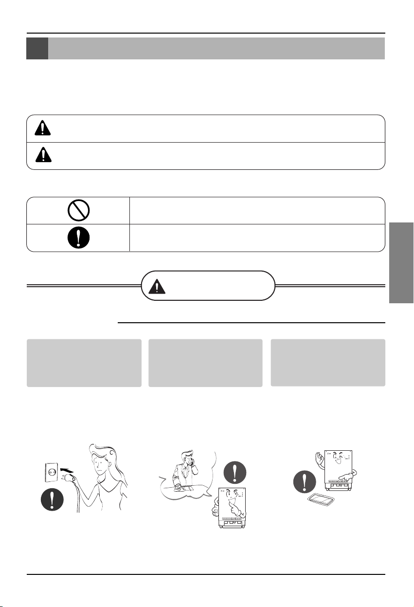
Precauciones de seguridad
Manual de instalación 3
ESPAÑOL
No encienda ni apague la
unidad insertando o
estirando del enchufe.
• Podría producirse una
descarga eléctrica o
incendio debido a la
generación de calor.
Solicite la instalación del
producto en el Centro de
servicio técnico o tienda
especializada.
• Podría producirse un
accidente, descarga
eléctrica, explosión o
lesiones.
Utilice piezas estándar.
• La utilización de piezas
no estándar podría
producir una descarga
eléctrica, explosión, lesión
o avería.
■ Funcionamiento
BNU-LW
BNU-LW
Precauciones de seguridad
Para evitar lesiones al usuario o a otras personas y daños materiales, deben seguirse estas
instrucciones.
■ Una utilización incorrecta por ignorar las instrucciones provocará lesiones o daños. La
gravedad se clasifica mediante las siguientes indicaciones.
■ Los significados de los símbolos utilizados en este manual se muestran abajo.
ADVERTENCIA
PRECAUCIÓN
Este símbolo indica la posibilidad de muerte o lesión grave.
Este símbolo indica la posibilidad de lesiones o daños.
No lo haga.
Asegúrese de seguir las instrucciones.
Advertencia
Piezas estándar

Precauciones de seguridad
4 Lonworks Gateway
Si entra agua en el producto, apague el
interruptor del cuerpo principal del aparato.
• Póngase en contacto con el Centro de servicio
técnico después de haber sacado el enchufe
de la toma.
Mantenga alejado el producto de lugares
que puedan tener humedad.
• El agua puede entrar en la unidad y deteriorar
el aislamiento. Podría producirse una descarga
eléctrica.
BNU-LW
BNU-LW
■ Durante el uso
Cuando desee volver a
instalar el producto,
póngase en contacto con el
Centro de servicio técnico o
una tienda especializada.
• Podría producirse un
accidente, descarga eléctrica,
explosión o lesiones.
No utilice el cable de
alimentación cerca de gas
inflamable o combustibles,
tales como la gasolina,
benceno, disolvente, etc.
• Podría producirse una
explosión o incendio.
No desarme aleatoriamente
ni repare o remodele el
producto.
• Podría producirse un
incendio y una descarga
eléctrica.
BNU-LW
BNU-LW
Wax
Thinner
BNU-LW
No cambie ni alargue el
conductor aleatoriamente.
• Podría producirse un
incendio y una descarga
eléctrica.
No utilice con
multiconectores.
• Podría producirse un
incendio y una descarga
eléctrica.
Desenchufe la unidad si
percibe un sonido extraño,
olores o si sale humo.
• Podría producirse un
incendio o una descarga
eléctrica.
BNU-LW
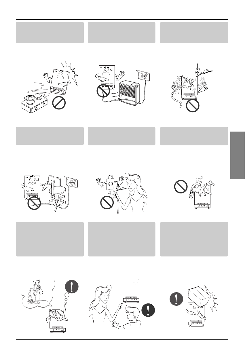
Precauciones de seguridad
Manual de instalación 5
ESPAÑOL
No coloque armas de fuego
cerca del producto.
• Podría producirse un
incendio.
No coloque un calentador
eléctrico o conductor cerca
del producto.
• Podría producirse un
incendio y una descarga
eléctrica.
No vierta agua en el interior
del producto.
• Podría producirse una
descarga eléctrica y una
avería.
BNU
-LW
BNU-LW
BNU-LW
No coloque objetos pesados
sobre el cable.
• Podría producirse un
incendio y una descarga
eléctrica.
Sujete la enchufe por la
cabeza al sacarla.
• Podría ocasionar una
descarga eléctrica y
daños.
No coloque objetos pesados
sobre el producto.
• Podría producirse una
avería en el producto.
BNU-LW
BNU-LW
Si el producto se sumerge
en agua, no se hará
responsable ni el Centro de
servicio técnico ni la tienda
especializada.
• Soy responsable del
incendio y descarga
eléctrica.
Evite que los niños manejen
el producto.
• Podría producirse un
accidente y una avería en
el producto.
No golpee el producto.
• En caso de que se
produzcan golpes en el
producto, soy
responsable de la avería.
BNU-LW
BNU-LW
BNU-LW
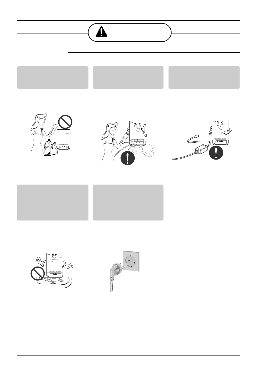
Precauciones de seguridad
6 Lonworks Gateway
■ Durante el uso
PRECAUCIÓN
Limpie cuidadosamente
utilizando un paño suave o
similar.
• Podría producirse un
incendio y una alteración
del producto.
No coloque ningún objeto
con agua sobre la
superficie.
• Podría producirse una
avería en el producto.
Utilice un adaptador
recomendado.
• De lo contrario, podría
producirse una avería en
el producto.
BNU-LW
Wax
Thinner
BNU-LW
BNU-LW
Evite que objetos metálicos
como collares, monedas,
llaves o relojes, entren en
contacto con la batería,
aunque sea por un momento.
• Podría producirse una
avería en el producto y
lesiones.
Sujete el enchufe por la
cabeza al sacarlo.
• Podría ocasionar una
descarga eléctrica y
daños.
BNU-LW
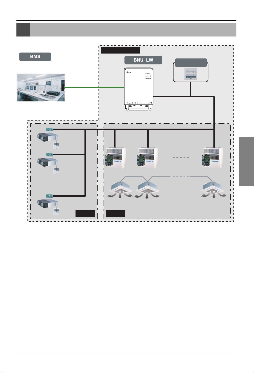
Diagrama general del sistema
Manual de instalación 7
ESPAÑOL
Diagrama general del sistema
Controlador
central simple
VentilaciónA/C
Comunicación 485
* Puede conectarse a 64 unidades interiores (ventilación + aire acondicionado)
Suministro LG
Diagrama general del sistema
* PNF-B16A1 (Lon Gateway) puede utilizarse en conexión con el controlador central
simple.
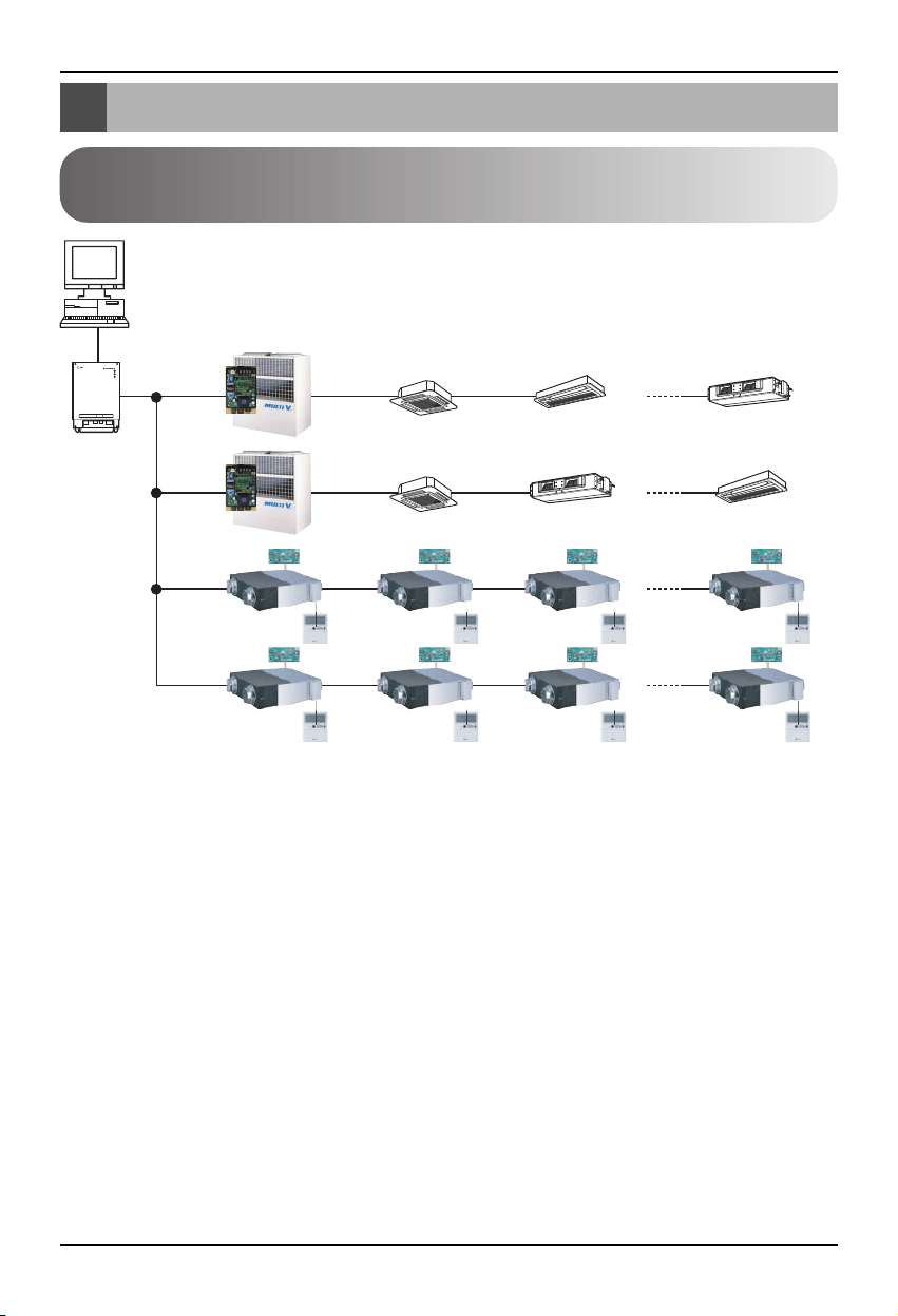
Diagrama de cableado externo
8 Lonworks Gateway
Protocolo LON
Sistema BMS
BNU-LW
RS485
RI485
Dirección del controlador central(0.0)
(0.1)............(0.F)
Dirección del controlador central(1.0)
Dirección del
controlador central(2.0)
Dirección del
controlador central(2.4)
(2.1) (2.2) (2.3)
(2.5) (2.6) (2.7)
(1.1)............(1.F)
Aire acondicionado
RI485
<Número máximo de unidades interiores conectadas: 64 unidades>
• Cuando la dirección de la unidad interior del aire acondicionado se duplique con la de la unidad de
ventilación, ésta no funcionará con normalidad.
• A BNU-LW se pueden conectar un máximo de 64 unidades de la unidad interior (aire acondicionado
+ ventilación).
• Se recomienda conectar 16 unidades de PI485 y un máximo de d32 PI485 unidades a BNU-LW.
• Los productos de ventilación no pueden interconectarse con el controlador central simple.
Diagrama de cableado externo
Cómo configurar la dirección del controlador central en la
unidad interior conectada a BNU-LW (Lonworks Gateway).
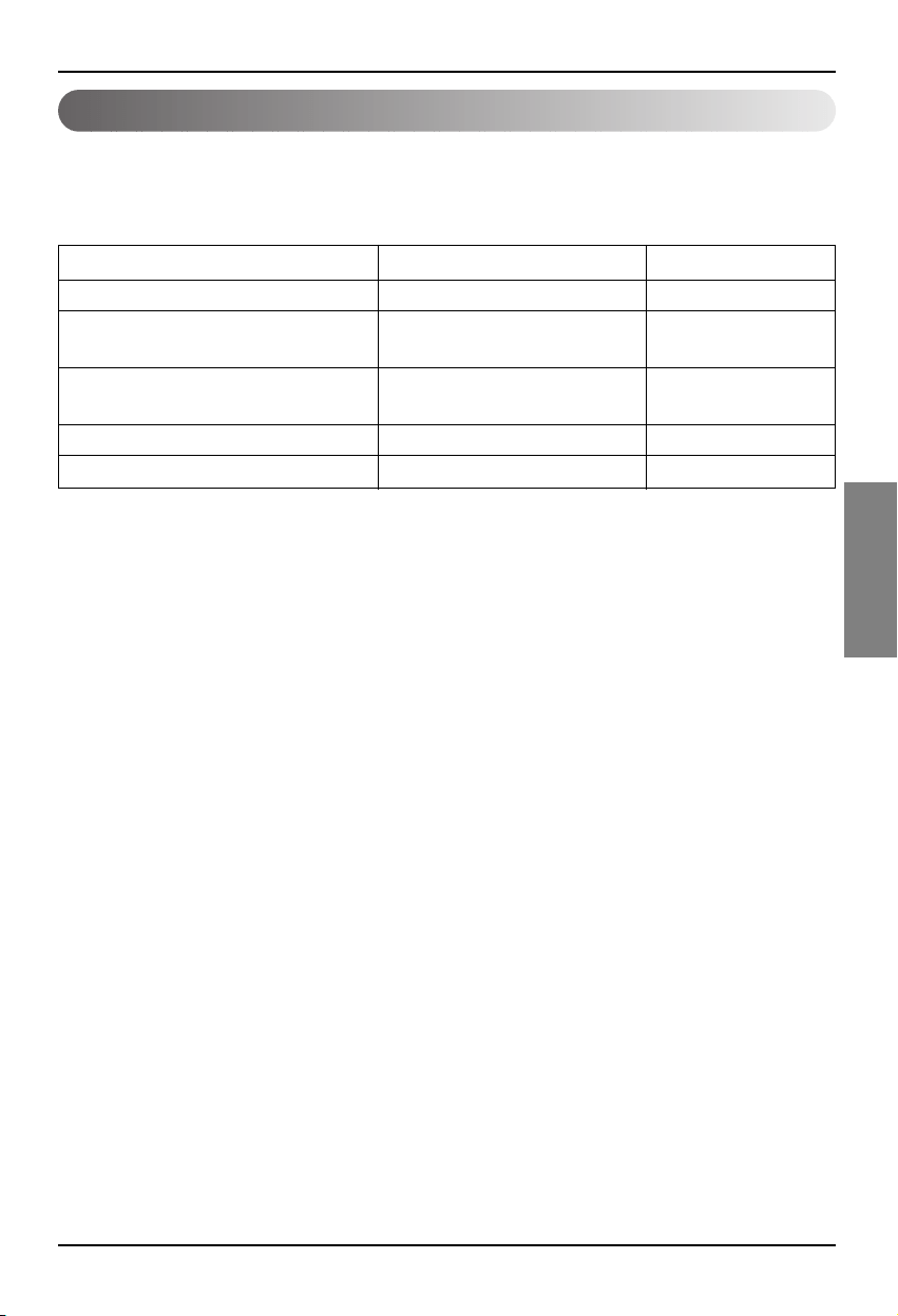
Diagrama de cableado externo
Manual de instalación 9
ESPAÑOL
1. Especificación de la línea de comunicación RS-485: 0,75mm2 o superior, 2C blindajes, producto
con producto: 200m, longitud total: 1km
2. Línea de comunicación FT-10: Consultar la tabla siguiente
* Distancia entre nodos (máx.): 250m, distancia máxima: 450m
* AWG: Sistema americano de calibres de alambres.
Tipo de cable Grosor de la línea (AWG) Diámetro
TIA 568A Category 5 cable 24 0.5mm
Belden 88471 (PVC jacket) or 16 1.3mm
equivalent cable
Belden 85102(Tefzel jacket) or 16 1.3mm
equal cable
Level IV cable 22 0.65mm
JY(st)Y 2x2x0.8 20.4 0.8mm
Especificación de la línea de comunicación
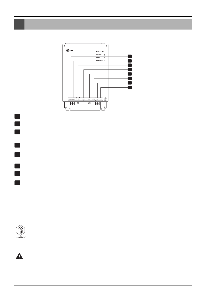
Nombre de cada pieza
10 Lonworks Gateway
Nombre de cada pieza
1
2
3
4
5
6
7
8
BUS_A: Línea de comunicación 485, A (+)
BUS_B: Línea de comunicación 485, B (-)
F1, F2: Conexión del punto de contacto en la función de detección de incendios
(dispositivo externo)
LAN: Puerto LAN necesario para la función web
LON: Línea de comunicación TP/FT-10 (línea de sistema de comunicación Lonworks)
sin polaridad.
PWR: Conexión a adaptador de potencia, 12 V de CC
12V: Conexión cuando no se utilice el adaptador de potencia de 12V de CC
GND: Conexión cuando no se utilice el adaptador GNS.
ALIVE/WINK (ACTIVO/PARPADEO): Parpadea cada segundo cuando todo es normal
Parpadea 5 veces cuando recibe un comando WINK (parpadeo) desde el sistema
Lonworks (verde)
SERVICE (SERVICIO): Se desactiva cuando todo es normal y genera destellos cuando
no está conectado al sistema Lonworks. Se activa cuando se pulsa el interruptor de
servicio.
SERVICE SWITCH (INTERRUPTOR DE SERVICIO): Al pulsar el interruptor el
identificador único (neuron ID) se transmite al sistema Lonworks y el LED de servicio
se activa.
El producto BNU-LW (PNF-B16A1) cuenta con la certificación LON-MARK, un
estándar internacional. (Lon Mark, versión 3.3)
1
8
2
3
4
5
6
7
LONWORKS GATEWAY
No. 6 y No. 7, 8 son para la alimentación. Por lo tanto, sólo debe utilizarse una de ambas
combinaciones.
Si se utiliza 12 V DC para la alimentación, conecte el No. 6 (no es necesario utilizar el No. 7, 8).
Si NO se utiliza 12 V DC para la alimentación, conecte el No. 7, 8 (no es necesario utilizar el No. 6).
Advertencia
Orden de instalación
Manual de instalación 11
ESPAÑOL
Orden de instalación
1. Instale el producto según la configuración de la dirección del controlador central de la unidad
interior y según el DIP S/W de PI485. (Posicione el interruptor DIP número 4 en “ON”, para su
activación).
(Consulte el manual de instalación de PI485 para más detalles).
2. Conecte BUS_A y BUS_B (línea de comunicación 485) mientras presta atención a la polaridad de
la conexión. (Consulte la siguiente página).
3. LON (línea TP/FT-10
➡
➡Conexión de la línea de comunicación Lonworks Gateway) La línea de
comunicación TP/FT-10 no tiene polaridad.
Conectar las 2 líneas de comunicación a BMS.
4. PWR (Suministro eléctrico)
Puede seleccionar cualquiera de los dos para el suministro eléctrico.
Utilice el adaptador de corriente de 12V de CC.
Conecte al número 6, en nombre de cada pieza.
Cuando se pueda obtener un adaptador de 12V de CC por separado
Conectar 12V y proceder a la puesta a tierra de los terminales 7 y 8.
5. Al pulsar el interruptor de servicio tras conectar el sistema Lonworks, el LED de servicio se activará
y el identificador único (neuron ID) se transmitirá automáticamente al sistema Lonworks.
6. Revise si el LED de servicio presenta un estado normal (posición: desactivado “OFF”) durante los
primeros 10 minutos. Si el LED de servicio no presente ningún problema, la instalación se habrá
realizado con normalidad.
7. Cuando utilice el puerto de detección de incendios, conecte los dos terminales del sensor detector
de fuego en F1 y F2 respectivamente.
(El sensor de detección de incendios debe utilizarse para una salida de CC de 12V o superior).
8. Después de la instalación, conecte el cable LAN entre los ordenadores para utilizar el servidor web
de manera que pueda revisar si el producto LG se ha instalado con normalidad. – Consulte la
parte de la función de diagnosis remota (página 16) para más detalles.
When connecting the signal line to the terminal of Lonworks Gateway, always use a
manual driver.
(Careful attention is required not to damage the terminal block and PCB.)
Precaución
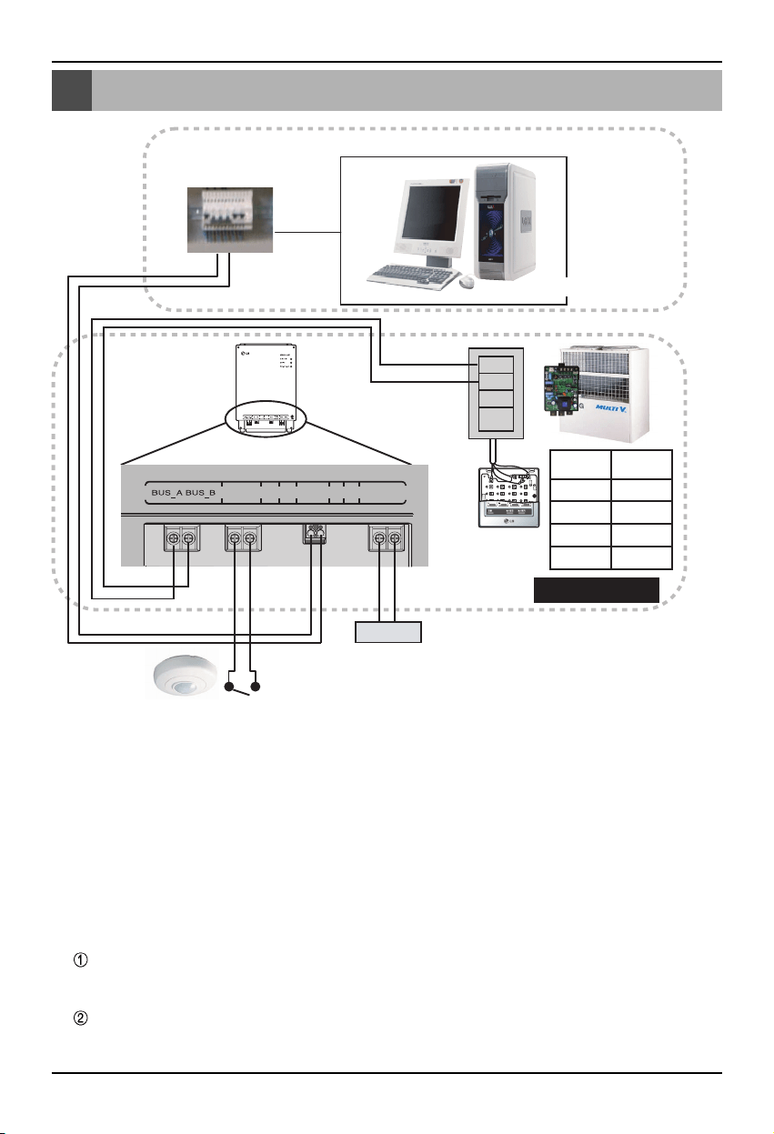
Orden de cableado BNU-LW
12 Lonworks Gateway
Orden de cableado BNU-LW
A
B
+10V
GND
TP/FT-10
Adaptador
LonWorks
Potencia
Control BMS (PC)
Sensor detector de incendios
(Uso de 12V de CC o inferior)
F1 F2 LAN LON PWR 12V GND
Terminal
PI485
Controlador
central
PI485
VOC
GND
C
D
10V
GND
BUS_A
BUS_B
LG NO suministra esta sección (conexión e instalación)
Suministro LG
[Orden del cableado]
1. Conectar la línea de comunicación 485
- Prestar atención a la polaridad BUS A y BUS B
(Consultar el manual G/W para más información
sobre DIP S/W para 485 G/W).
2. Conectar la línea de comunicación Lonworks
(TP/FT-10)
- Sin polaridad.
3. Suministro eléctrico (Seleccionar entre el
número 1 o el 2)
Uso de adaptador de 12V de CC
- Conectar a la clavija número 6 desde el
nombre de cada pieza.
Suministrar 12V de CC para la instalación
- Conectar 12V y proceder a la puesta a
tierra de los terminales 7 y 8.
4. Interconectar con el controlador central simple
- Ajustar DIP S/W número 2 del controlador
central simple en activado “ON” y configurar
el ajuste según la dirección rotativa S/W.
(Consultar la configuración al conectar a un
controlador central simple (página 20) para
más detalles).
5. Conectar el sensor de detección de incendios
- Cuando la señal de 12V de CC o inferior se
transmita en caso de incendio, la unidad
interior y el producto de ventilación
conectado al BNU-LW se desactivarán.
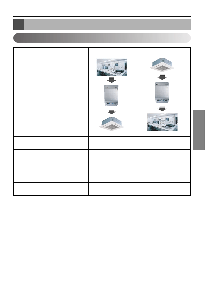
Tabla de funciones aire acondicionado/ventilación
Manual de instalación 13
ESPAÑOL
Tabla de funciones aire acondicionado/ventilación
Función de la unidad interior de aire acondicionado
Control individual de la unidad interior O O
Cambio en el modo de operaciónO O
Cambio en el nivel del ventilador O O
Función de ajuste de la temperatura O O
Función de bloqueo O O
Dirección automática del ventilador O O
Revisión de la temperatura de la unidad interior
XO
Revisión de error X O
Operación/parada simultánea O X
Función
BMS
BNU-LW
Aire acondicion
BMS
BNU-LW
Aire acondicion
Clasificación Control Supervisar
Función de unión (conexión): La función de unión se refiere a la situación en la que la salida de una
unidad se ha unido a la entrada de otra unidad y el proceso de entrada
al de salida. La función de unión también es posible con la unidad Lon
de otro fabricante.
Ejemplo: Cuando la salida “ON/OFF” (activado/desactivado) de la unidad interior número 1 está
unida a la entrada “ON/OFF” de la unidad interior número 2, cuando la unidad interior
número 1 está activada, la unidad interior número 2 se activa también tras recibir la señal.
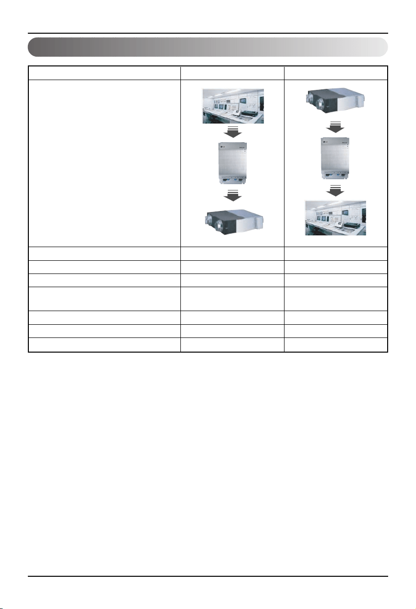
Tabla de funciones aire acondicionado/ventilación
14 Lonworks Gateway
Función de ventilación en la unidad interior
Control individual de la unidad interior O O
Cambio en el modo de operaciónO O
Cambio en el nivel del ventilador O O
Modo de funcionamiento según el usuario
OO
(ventilación rápida, ahorro de energía, calor)
Función de bloqueo O O
Revisión de error X O
Operación/parada simultánea O X
Función
BMS
BNU-LW
Ventilation
BMS
BNU-LW
Ventilation
Clasificación Control Supervisar
Función de unión (conexión): La función de unión se refiere a la situación en la que la salida de una
unidad se ha unido a la entrada de otra unidad y el proceso de entrada
al de salida. La función de unión también es posible con la unidad Lon
de otro fabricante.
Ejemplo: Cuando la salida “ON/OFF” (activado/desactivado) de la unidad interior número 1 está
unida a la entrada “ON/OFF” de la unidad interior número 2, cuando la unidad interior
número 1 está activada, la unidad interior número 2 se activa también tras recibir la señal.
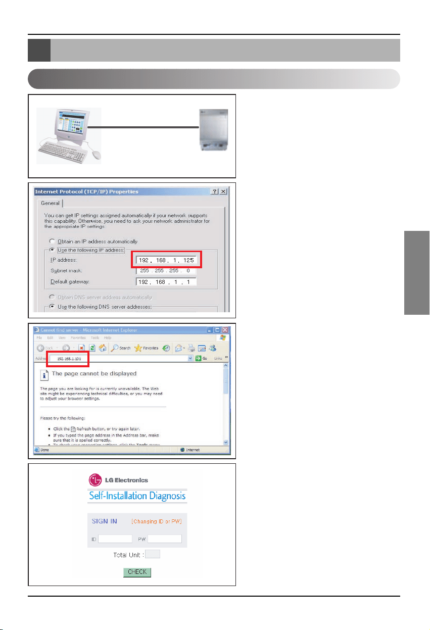
Función de diagnosis remota BNU-LW
Manual de instalación 15
ESPAÑOL
1. Conectar la línea LAN al PC y al puerto
LAN de la unidad BNU-LW.
2. Configurar la IP de la red en el PC
utilizado, indicando: 192.168.1xxx
(excepto 101).
3. Introducir 192.168.1.101 en Internet
Explorer.
4. La imagen anterior aparece cuando la
conexión se ha realizado con
normalidad.
Identificación (ID) inicial: lonwork
Contraseña inicial: lonwork
Indicar el número total de unidades
interiores conectadas al conjunto.
Función de diagnosis remota BNU-LW
Método de configuración
LAN(cross cable)

Función de diagnosis remota BNU-LW
16 Lonworks Gateway
Configuración
• Después de introducir la
identificación y la contraseña, los
productos de ventilación y aire
acondicionado conectados
actualmente deben mostrarse
según se indica en la siguiente
figura.
• La parte "A" muestra el número de
productos de aire acondicionado y
calefacción conectados en estos
momentos.
• Cuando quiera controlar un
producto: ➀ Seleccione el producto;
➁ Ajuste la dirección; ➂ Comando
"ON/OFF” (activado/desactivado);
➃ Seleccione el modo; ➄ Haga clic
en revisar para controlar el
producto.
• Cuando quiera revisar el estado
actual: ➅ Haga clic en Cargar y
podrá revisar el estado de la unidad
interior en la parte “B”.
• Cuando quiera cambiar la IP, haga
clic en [Configurar lugar de red]
para cambiar la dirección IP.
"A"
"B"
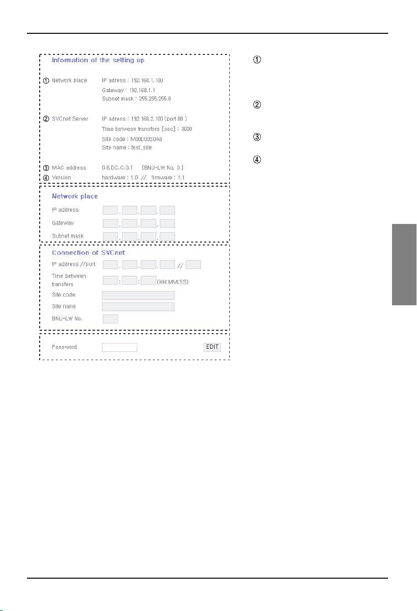
Función de diagnosis remota BNU-LW
Manual de instalación 17
ESPAÑOL
A
B
C
D
A: Muestra información sobre la
dirección IP actual, la puerta de
enlace (Gateway) y la máscara de
subred.
Cuando quiera utilizar el servidor
SVCnet, muestra información del
servidor SVCnet.
Muestra información sobre la
dirección MAC.
Muestra información sobre la
versión actual del BNU-LW.
B: Cuando quiera cambiar la IP, la puerta
de enlace o información de la máscara
de subred, pulse el botón Editar
situado junto a la información que
desea cambiar.
C: Este es el espacio para introducir la
información del servidor SVCnet a
conectar.
El servidor SVCnet es un servicio que
supervisa el estado del aire
acondicionado conectado al BNU-LW
a través de la conexión LAN, función
que en un futuro realizará el Centro de
servicios electrónicos de LG, a fin de
facilitar un aviso anticipado en caso
de incidencia.
D: Para prevenir un cambio de red o
cualquier otra modificación arbitraria,
se dispone de una función de
seguridad para que indique una
contraseña de inicio de sesión y
cambie la configuración de la red.
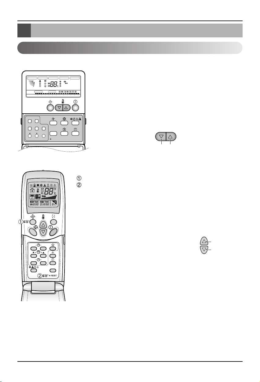
Ajuste de la dirección de la unidad interior
18 Lonworks Gateway
Ajuste de la dirección de la unidad interior
Ajuste de la dirección de la unidad interior
Cuando utilice un controlador remoto por cable
Cuando utilice un controlador remoto inalámbrico
Timer Cancel
Program Week
Hour Min
Holiday
Set/Clr
RESET
ZONE
1234
Operation unit
Humidify
JET
AUTO
AUTO SWING OPERATION
FAN SPEED
Program set
SUB FUNCTION
SET TEMP
Room Temp
HI
MED
LO
Heater
Defrost
Filter
Preheat
Out door
Time
Timer
On
Set no. Time
Off
01 03 05 07 09 11 13 15 17 19 21 23
Plasma
ON OFF
SET
CANCEL
PLASMA
Número de grupo
Número de
unidad interior
Ajuste de temperatura
1. Pulse simultáneamente y durante 3 segundos los botones de
ajustar/cancelar día de semana y reserva.
2. Utilizando el botón de ajuste de temperatura, indique la
dirección de la unidad interior.
Rango de ajuste: 00~FF
3. Cuando pulse en los botones cancelar/ajustar día de semana y
reserva, de forma simultánea y durante 3 segundos, se
completará el ajuste de la dirección.
Modo de configuración de dirección
1.
Pulse el botón superior izquierdo durante más de 3 segundos.
Mientras mantiene pulsado el botón superior izquierdo, pulse el botón Reset
(resetear).
❈
Los mandos a distancia inalámbricos tienen diferentes formas dependiendo
del modelo.
2. Utilizando el botón de ajuste de temperatura, indique la dirección de la unidad
interior.
Rango de ajuste: 00~FF
3. Tras configurar la dirección, pulse el botón "ON/OFF"
hacia el tiempo en la unidad interior número 1.
4. La unidad interior mostrará la dirección para que
proceda a su correspondiente ajuste.
(La hora y el método de mostrar la dirección pueden
variar según el tipo de unidad interior).
5. Reestablezca el controlador remoto para utilizar el modo de operación general.
Modo de comprobación de dirección
1. Con el botón de la parte superior derecha pulsado, pulse el botón Restablecer.
(Pulse el botón izquierdo durante más de 3 segundos).
2. Pulse el botón “ON/OFF” hacia el tiempo en la unidad interior número 1, y ésta
mostrará la dirección a ajustar en la ventana de visualización.
(La hora y el método de mostrar la dirección pueden variar según el tipo de
unidad interior).
3. Reestablezca el controlador remoto para utilizar el modo de operación general.
❈ La función anterior puede que no funcione en algunos controladores remotos dependiendo de la
fecha de fabricación del controlador remoto por cable o inalámbrico.
No es relevante para el uso del cliente y usted puede ajustar la dirección durante la instalación
mediante un controlador remoto que disponga de la funcionalidad de ajuste.
Número de grupo
Número de
unidad interior
Ajuste de
temperatura

Interconexión con un controlador central simple
Manual de instalación 19
ESPAÑOL
Interconexión con un controlador central simple
Como interconectar con un controlador
central simple
• Al interconectar con un controlador central simple, active el
DIP S/W número 2 del controlador central simple.
• Ajuste el S/W rotativo según la dirección de grupo en la
unidad interior que quiera controlar.
Cómo configurar PI-485.
Cómo configurar PI-485.
• BNU-LW utiliza el protocolo de comunicación LGAP.
Puede posicionar el DIP S/W número 1 y el número 4 de PI-
485 en “ON” (activado).
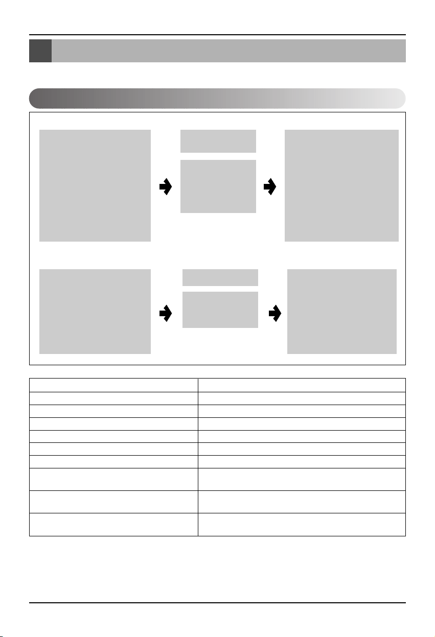
Apéndice
20 Lonworks Gateway
Apéndice
Objetos A/C
• El apéndice contiene información necesaria para la interconexión con BMS y no necesaria para la
instalación.
Bloqueo de función estándar
SCC(8500)FB
Unidad
interior/ventilador,
red de variables
Control total
SNVT
_
switch nviOnOff
SNVT
_
hvac
_
mode nviHeatCool
SNVT
_
switch nviFanSpeedcmd
SNVT
_
switch nviLock
SNVT
_
switch nviSwing
SNVT
_
switch nviSetPoint
SNVT
_
switch nviUser
SNVT
_
switch nviSpaceTemp
SNVT
_
switch nvoOnOff
SNVT
_
hvac
_
mode nvoHeatCool
SNVT
_
switch nvoFanSpeed
SNVT
_
switch nvoLock
SNVT
_
switch nvoSwing
SNVT
_
temp
_
P nvoSetPoint
SNVT
_
hvac
_
status nvoUnitStatus
SNVT
_
count nvoUser
switch(3200)fb
Total
Control
SNVT
_
switch
nviTotalOnOff
_
Indoor
SNVT
_
switch
nviTotalOnOff
_
Vent
SNVT
_
switch nvoSwitch
• Se puede habilitar el control y monitorización tal y como se muestra en la figura para una unidad de
ventilación/aire acondicionado.
• La variable de la red puede diferir de la real.
(Consulte el archivo XIF para una variable de red correcta).
Control Supervisar
Comando activado/desactivado
Comando de selección de modo
Comando de selección de nivel del ventilador
Comando de bloqueo de unidad interior
Comando de dirección del ventilador
Comando de configuración de temperatura
Comando de función adicional de ventilación
(Sólo aplicable a productos de ventilación)
Control total activado/desactivado del aire
acondicionado
Control total activado/desactivado de ventilación
Estado de monitorización activado/desactivado
Monitorización del estado de modo
Monitorización del estado de nivel del ventilador
Monitorización del estado de bloqueo
Monitorización del estado de dirección del ventilador
Monitorización del estado de configuración de temperatura
Monitorización de temperatura actual
Pantalla de error
Monitorización del estado de función adicional de
ventilación(Sólo aplicable a productos de ventilación)
Apéndice
Manual de instalación 21
ESPAÑOL
Punto de control/monitorización del aire acondicionado
1
Activado/Desactivado (config.)
SNVT_switch nviOnOff_nn Entrada
Detener
Operación
2
Activado/Desactivado (estado)
SNVT_switch nvoOnOff_nn Salida
Detener
Operación
3 Bloqueo (config.) SNVT_switch nviLock_nn Entrada
Cancelar
Configuración
4 Bloqueo (estado) SNVT_switch nvoLock_nn Salida
Cancelar
Configuración
5 Modo Operación (config.) SNVT_hvac_modenviHeatCool_nn Entrada
Automático Calefacción
Enfriamiento
Ventilador
Deshumidificación
6 Modo Operación (estado) SNVT_hvac_mode nviHeatCool_nn Salida
Automático Calefacción
Enfriamiento
Ventilador
Deshumidificación
7 Oscilación (config.) SNVT_switch nviSwing_nn Entrada
Cancelar
Configuración
8 Oscilación (estado) SNVT_switch nvoSwing_nn Salida
Cancelar
Configuración
9
Velocidad del ventilador (config.)
SNVT_switch nviFanSpeedCmd_nn Entrada Bajo Medio Alto
Automático
Débil
10
Velocidad del ventilador (estado)
SNVT_switch nvoFanSpeed_nn Salida Bajo Medio Alto
Automático
Débil
11
Configurar temperatura ambiente
SNVT_temp_p nviSetPointCmd_nn Entradat °C
12
Configurar temperatura ambiente
SNVT_temp_p nvoSetPoint_nn Salida °C
13 Temperatura ambiente SNVT_temp_p nvoSpaceTemp_nn Salida °C
14 Código de error SNVT_hvac_status nvoUnitStatus_nn Salida
Consultar el código de error de aire acondicionado de
LG.
Nº de
punto
Nombre
Tipo de
objeto
Unidad
Código 0 Código 1 Código 2 Código 3 Código 4 Código 5 Código
9
Código
14
Nombre del objeto
(nn: Dirección de la unidad interior/grupo
de ventilación y aire acondicionado).

Apéndice
22 Lonworks Gateway
Punto de control/monitorización de la ventilación
1
Activado/Desactivado (config.)
SNVT_switch nviOnOff_nn Entrada Detener
Funcionamiento
2
Activado/Desactivado (estado)
SNVT_switch nvoOnOff_nn Salida Detener
Funcionamiento
3 Bloqueo (config.) SNVT_switch nviLock_nn Entrada Cancelar
Configuración
4 Bloqueo (estado) SNVT_switch nvoLock_nn Salida Cancelar
Configuración
5 Modo Operación (config.) SNVT_hvac_modenviHeatCool_nn Entrada
Automático Calefacción
Normal
6 Modo Operación (estado) SNVT_hvac_mode nviHeatCool_nn Salida
Automático Calefacción
Normal
7
Velocidad del ventilador (config.)
SNVT_switch nviFanSpeedCmd_nn Entrada Bajo Alto Muy alto
8
Velocidad del ventilador (estado)
SNVT_switch nvoFanSpeed_nn Salida Bajo Alto Muy alto
9Código de error SNVT_hvac_status nvoUnitStatus_nn Salida
Consultar el código de error de aire acondicionado de LG.
10 Modo Usuario (config.) SNVT_count nviUser_nn Salida Rápido
Ahorro de energía
Calor
11 Modo Usuario (estado) SNVT_count nvoUser_nn Salida Rápido
Ahorro de energía
Calor
Nº de
punto
Nombre
Tipo de
objeto
Unidad
Código 0 Código 1 Código 2 Código 3 Código 5 Código 9
Nombre del objeto
(nn: Dirección de la unidad interior/grupo
de ventilación y aire acondicionado).
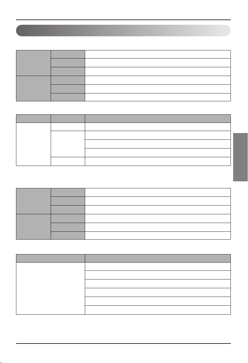
Apéndice
Manual de instalación 23
ESPAÑOL
Variables de red
1) Operación individual (aire acondicionado/ventilación)
Rango válido
SNVT_switch
(índice: 95)
NV Campo Operación
Función Entrada de parada/operación
Entrada Uso de NV Variable en entrada de red : SNVT_switch nviOnOff_n
Operación
Controla la operación/parada de cada producto (aire acondicionado/ventilación)
Función Pantalla de estado de operación/parada
Salida Uso de NV Variable en salida de red: SNVT_switch nvoOnOff_n
Operación
Controla el estado de operación de cada producto (aire acondicionado/ventilación)
2) Entrada/salida del modo de operación (aire acondicionado/ventilación)
Función Entrada del comando del modo de operación
Entrada Uso de NV Variable en entrada de red : SNVT_hvac_mode nviHeatCool_n
Operación
Controla la operación/parada de cada producto de aire acondicionado/ventilación.
Función Pantalla de estado del modo de operación
Salida Uso de NV Variable en salida de red : SNVT_hvac_mode nvoHeatCool_n
Operación
Controla el estado de operación de cada producto de aire acondicionado/ventilación.
Valor No utilizado (normalmente con ajuste en 0%)
0 = Aire acondicionado/producto de ventilación desactivado (OFF)
Estado 1 = Aire acondicionado/producto de ventilación activado (ON)
Valor predeterminado
HVAC_AUTO:0 = Modo automático (auto), ventilación automática
HVAC_HEAT:1 = Modo de calefacción (calor), ventilación
HVAC_COOL: 3 = Modo refrigeración (frío)
HVAC_FAN_ONLY:9 = Modo ventilador (ventilador), ventilación normal
HVAC_DEHUMID:14 = Modo seco (deshumidificación)
Valor predeterminado
Rango válido
SNVT_hvac_mode
(índice: 108)
NV Operación

Apéndice
24 Lonworks Gateway
1: Aire acondicionado, ventilador con nivel de ventilación bajo
2: Ventilador con aire acondicionado medio, ventilador con nivel de ventilación alto
Valor 3:
Ventilador con aire acondicionado alto, ventilador con nivel de ventilación muy alto
4: Aire acondicionado, ventilador con ventilación automática
5. Aire acondicionado con ventilador en nivel muy bajo
Estado 0: Producto no aplicable, 1: Producto aplicable
Valor predeterminado
3) Entrada/salida del comando de nivel del ventilador (aire acondicionado/ventilación)
Rango válido
SNVT_switch
(índice: 95)
NV Campo Operación
Función Entrada del comando de nivel del ventilador
Entrada Uso de NV Variable en entrada de red : SNVT_switc nviFanSpeedCmd_n
Operación Controla el nivel del ventilador en cada unidad interior.
Función Pantalla de estado de nivel del ventilador
Salida Using NV Variable en salida de red : SNVT_switch nvoFanSpeed_n
Operación
Controla el nivel del ventilador en cada producto (aire acondicionado/ventilación)
Valor No utilizado (normalmente con ajuste en 0%)
0 = Aire acondicionado/producto de ventilación con bloqueo desactivado (OFF)
Estado 1 = Aire acondicionado/producto de ventilación con bloqueo activado (ON)
Valor predeterminado
4) Entrada/salida de bloqueo (aire acondicionado/ventilación)
Rango válido
SNVT_switch
(índice: 95)
NV Campo Operación
Función Entrada de comando de ajuste de bloqueo
Entrada Uso de NV Variable en entrada de red : SNVT_switch nviLock_n
Operación
Controla el estado de bloqueo de cada producto (aire acondicionado/ventilación)
Función Pantalla de estado de bloqueo
Salida Using NV Variable en salida de red : SNVT_switch nvoLock_n
Operación
Controla el estado de bloqueo de cada producto (aire acondicionado/ventilación)
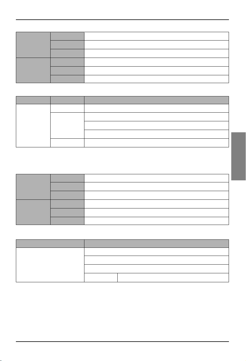
Apéndice
Manual de instalación 25
ESPAÑOL
Valor No utilizado (normalmente con ajuste en 0%)
0 = Dirección del ventilador fija para el producto de aire acondicionado
Estado 1 =
Dirección del ventilador automática para el producto de aire acondicionado
Valor predeterminado
5) Entrada/salida automática en la dirección del ventilador (sólo aplicable al aire acondicionado)
Rango válido
SNVT_switch
( Index : 95 )
NV Campo Operación
Función Entrada de comando de dirección automática de ventilador
Entrada Uso de NV Variable en entrada de red : SNVT_switch nviSwing_n
Operación
Controla la dirección del ventilador en cada producto (aire acondicionado/ventilación)
Función Pantalla de estado de la dirección automática del ventilador
Salida Using NV Variable en salida de red : SNVT_switch nvoSwing_n
Operación
Controla la dirección del ventilador en cada producto (aire acondicionado/ventilación)
6) Entrada/salida de configuración de temperatura (sólo aplicable al aire acondicionado)
Función Entrada del rango para el ajuste de temperatura
Entrada Uso de NV Variable en entrada de red : SNVT_switch nviSetPoint_n
Operación
Controla el ajuste de temperatura de cada producto (aire acondicionado/ventilación)
Función Pantalla de estado del rango de ajuste de temperatura
Salida Uso de NV Variable en salida de red : SNVT_switch nvoSetPoint_n
Operación
Controla el ajuste de temperatura de cada producto (aire acondicionado/ventilación)
En modo frío : 18 ~ 30°C
En modo calor : 18 ~ 30°C
En modo Seco y modo Ventilador: no disponible
Valor predeterminado
Rango válido
SNVT_switch
(índice: 95)
NV Operación

Apéndice
26 Lonworks Gateway
7) Pantalla de estado de temperatura interior (sólo aplicable al aire acondicionado)
Función Pantalla de estado de temperatura interior
Salidat Uso de NV Variable en salida de red : SNVT_switch nvoSpaceTemp_n
Operación Controla la temperatura interior.
8) Salida de error (aire acondicionado/ventilación)
Función Pantalla de estado de error
Salida Uso de NV Variable en salida de red : SNVT_hvac_Status nvoUnitStatus_n
Operación
Controla el estado de error de cada producto (aire acondicionado/ventilación)
En modo frío : 10 ~ 40°C
En modo calor : 10 ~ 40°C
En modo Seco, modo Ventilador: no disponible
Valor predeterminado
Rango válido
SNVT_switch
(índice: 95)
NV Operación
Modo Pantalla de modo operativo en estos momentos
Entrada_calor_primaria No se utiliza
Salida_calor_secundaria No se utiliza
Entrada_frío No se utiliza
Entrada_frío No se utiliza
Econ_salida No se utiliza
Ventilador_salida No se utiliza
En_salida Pantalla de código de error
Rango válido
SNVT_switch
(índice: 112)
NV Campo Operación
* Consultar la tabla de códigos de error en el manual del producto para cada código concreto.
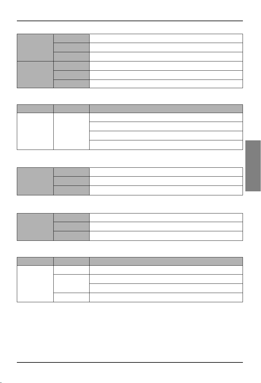
Apéndice
Manual de instalación 27
ESPAÑOL
10) Operación/parada total de la unidad interior de aire acondicionado
Función Entrada de comando de parada total
Entrada Uso de NV Variable en entrada de red : SNVT_switch nviTotalONOFF_indoor
Operación Activa o desactiva (ON/OFF) todas las unidades interiores.
11) Operación total/parada de ventilación en unidad interior
Función Entrada de comando de parada total
Entrada Uso de NV Variable en entrada de red : SNVT_switch nviTotalONOFF_indoor
Operación Activa o desactiva (ON/OFF) todas las unidades de ventilación.
0 = No utilizado
Valor
1 = Modo rápido
2 = Modo ahorro de energía
3 = Calor
9) Comando de función de ventilación (Sólo aplicable al producto de ventilación)
Rango válido
SNVT_count
(índice: 8)
NV Campo Operación
Función Entrada del modo de ventilación, operado por el usuario
Entrada Uso de NV Variable en entrada de red : SNVT_count nviUser_n
Operación Controla la función del producto en cada unidad de ventilación.
Función Estado del modo de ventilación, operado por el usuario
Salida Uso de NV Variable en salida de red : SNVT_count nvoUser_n
Operación Controla el estado de la función de cada producto de ventilación.
Valor No utilizado
Estado
1 = Todo ENCENDIDO unidad interior/vent.
0 = Todo APAGADO unidad interior/vent.
Valor predeterminado
Rango válido
SNVT_switch
( Index : 95 )
NV Campo Operación

Nota
28 Lonworks Gateway

FRANÇAIS
LG
BNU-LW(Lonworks Gateway)
LG
IMPORTANT
• Veuillez lire en entier ce manuel d'installation le
produit.
• Après avoir lu en entier ce manuel d'installation,
veuillez le conserver pour future consultation.
Manuel d’installation

2 Lonworks Gateway
BNU-LW (Lonworks Gateway)
TABLE DES MATIÈRES
Mesures de sécurité...............................................................................................3
Diagramme du système général...........................................................................7
Diagramme de l’installation électrique externe...................................................8
Comment mettre l’adresse pour la télécommande centrale de
l’appareil en salle connecté au BNU-LW (Lonworks Gateway)...........................8
Spécification de la ligne de communication .......................................................9
Nom de chaque partie .........................................................................................10
Schéma d’installation ..........................................................................................11
Schéma de l’installation électrique BNU-LW.....................................................12
Tableau des fonctions de l’air conditionné/ventilation ....................................13
Fonctions d’air conditionné de l’appareil en salle .............................................13
Fonction d’air conditionné de l’appareil en salle ...............................................14
Fonctions de diagnose à distance BNU-LW ......................................................15
Méthode de fixation ........................................................................................15
Configuration ....................................................................................................16
Fixation de l’adresse de l’appareil en salle .......................................................18
Fixation de l’adresse de l’appareil en salle .......................................................18
Interface avec la télécommande centrale simple..............................................19
Annexe ..................................................................................................................20
Objets A/C ........................................................................................................20
Point de contrôle/monitorage de l’air conditionné .............................................21
Point de contrôle/monitorage de ventilation......................................................22
Variables de réseau ..........................................................................................23
Mesures de sécurité
Manuel d’Installation 3
FRANÇAIS
Ne pas brancher ni
débrancher l’appareil
pour le mettre en marche
ou l’arrêter.
• Risque de décharge
électrique ou d’incendie
par suite de surchauffe.
Demander au service
central ou à un magasin
spécialisé l’outillage
nécessaire à l’installation
de l’appareil.
• Risque d’accident, de
décharge électrique,
d’explosion ou de
dommage.
Utilisez les pièces
standard.
• L’usage de piéces non
standard peut provoquer
décharge électrique,
explosion, dommage ou
panne.
■ Fonctionnement
BNU-LW
BNU-LW
Mesures de sécurité
Pour éviter que l’usager ou une autre personne se blesse ou que l’appareil subisse des
dommages matériels, respecter les indications ci-dessous.
■ Un usage incorrect dû au non-respect de ces instructions pourrait causer des dégâts ou
endommager l’appareil. Leur degré de gravité est classée de la manière suivante.
■
Voir ci-dessous la signification des symboles utilisés dans le manuel.
AVERTISSEMEN
T
PRÉCAUTION
Ce symbole indique un danger de mort ou de dommages graves.
Ce symbole indique un risque seulement pour l’appareil.
A ne pas faire.
Suivre les instructions
AVERTISSEMENT
Pièces standard

Mesures de sécurité
4 Lonworks Gateway
Au cas où de l’eau entrerait dans l’appareil, éteindre
l’interrupteur du corps principal de l’appareil.
• Après l’avoir débranché, contacter le
service central.
Maintenir l’appareil hors des lieux humides.
• De l’eau pourrait entrer dans l’appareil et
détériorer l’isolation. Risque de décharge
électrique.
BNU-LW
BNU-LW
■ Pendant l’utilisation.
Pendant la réinstallation de
l’appareile, informer le
service central ou le
magasin spécialisé.
• Risque d’accident, de
décharge électrique,
d’explosion, de dommage.
Ne pas utiliser le câble
d’alimentation près de gaz
inflammables ou de
combustibles tels que : essence,
benzène ou diluant, etc.
• Risque d’explosion ou
d’incendie.
Ne pas démonter au hasard
l’appareil, ni le réparer ni le
remodeler.
• Risque de décharge
électrique ou d’incendie.
BNU-LW
BNU-LW
Wax
Thinner
BNU-LW
Ne pas changer le
conducteur ni l’allonger.
• Risque d’incendie et de
décharge électrique.
Ne pas utiliser avec une
prise multiple.
• Risque d’incendie et de
décharge électrique.
Débrancher l’appareil s’il
émet des bruits, une odeur
ou de la fumée.
• Risque d’incendie et de
décharge électrique.
BNU-LW
Mesures de sécurité
Manuel d’Installation 5
FRANÇAIS
Ne pas placer d’ objets
incandescents (ayant une
flamme) près de l’appareil.
• Risque d’incendie.
Ne pas placer de radiateur
électrique ou de conducteur
près de l’appareil.
• Risque d’incendie et de
décharge électrique.
Ne pas renverser d’eau dans
l’appareil.
• Risque de décharge
électrique et de panne.
BNU
-LW
BNU-LW
BNU-LW
Ne pas placer d’objets
pesants sur le câble.
• Risque d’incendie et de
décharge électrique.
Tenir le câble par la prise
lors du débranchement.
•
Risque de décharge
électrique et de dommage.
Ne pas placer d’objets
pesants sur l’appareil.
• Risque de panne de
l’appareil.
BNU-LW
BNU-LW
En cas d’inondation de
l’appareil votre
responsabilité serait engagée
face au service centrale ou
au magasin spécialisé.
• Je suis responsable en
cas d’incendie et de
décharge électrique.
Eviter que l’appareil soit
manipulé par des enfants.
• Risque d’accident et de
panne de l’appareil.
Ne pas faire subir de choc à
l’appareil.
• Je suis responsable en
cas de panne pour raison
de choc.
BNU-LW
BNU-LW
BNU-LW

Mesures de sécurité
6 Lonworks Gateway
■ Pendant l’usage.
PRÉCAUTION
Nettoyer délicatement
l’appareil avec une matière
telle qu’un chiffon doux.
• Risque d’incendie ou de
modification de l’aspect
de l’appareil.
Ne placer aucune partie vitale
sur une surface mouillée.
• Risque de panne.
Utiliser l’adaptateur
recommandé.
• Risque de panne.
BNU-LW
Wax
Thinner
BNU-LW
BNU-LW
Eviter le contact avec des objets
métalliques tels que chaîne,
monnaie, clé, une montre qui
serait en contact avec la batterie
même pour peu de temps.
• Risque de panne ou de
dommage.
Tenir le câble par la prise
lors du débranchement.
• Risque de décharge
électrique ou de
dommage.
BNU-LW
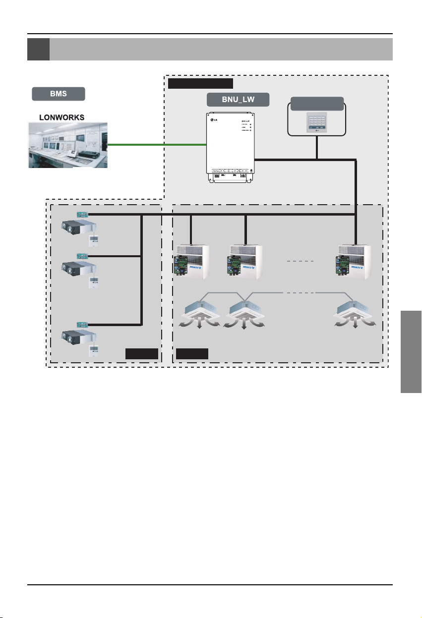
Diagramme du système général
Manuel d’Installation 7
FRANÇAIS
Diagramme du système général
Télécommande
centrale simple
Fourni par LG
Ventilation A/C
485 communication
* Peut être connecté à 64 appareils en salle (Ventilation + Air conditionné)
* Le PNF-B16A1 (Lon Gateway) peut être utilisé en connexion avec la télécommande
centrale simple.
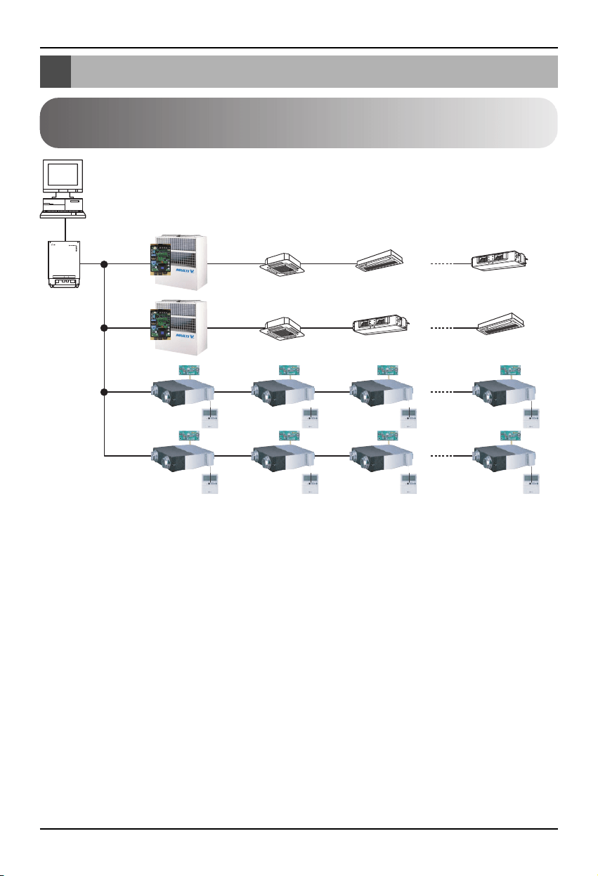
Diagramme de l’installation électrique externe
8 Lonworks Gateway
Protocole LON
Système BMS
BNU-LW
RS485
RI485
Adresse de la télécommande centrale(0.0)(0.1)............(0.F)
Adresse de la télécommande centrale(1.0)
Adresse de la
télécommande
centrale(2.0)
Adresse de la
télécommande
centrale(2.4)
(2.1) (2.2) (2.3)
(2.5) (2.6) (2.7)
(1.1)............(1.F)
Air conditionné
RI485
< Nombre maximal d’appareils en salle connectés : 64 unités>
• Lorsque l’adresse de l’appareil en salle de l’air conditionné est doublée avec celle de l’unité de
ventilation, ceci ne marchera pas correctement.
• Un maximum de 64 appareils en salle (Air conditionné + Ventilation) peut être connecté au BNU-LW.
• Il est recommandé de connecter 16 appareils à PI485 et un maximum de 32 appareils PI485 au
BNU-LW.
• Les produits de ventilation ne peuvent pas être opérés avec la télécommande centrale simple.
Diagramme de l’installation électrique externe
Comment mettre l’adresse pour la télécommande centrale de
l’appareil en salle connecté au BNU-LW (Lonworks Gateway)
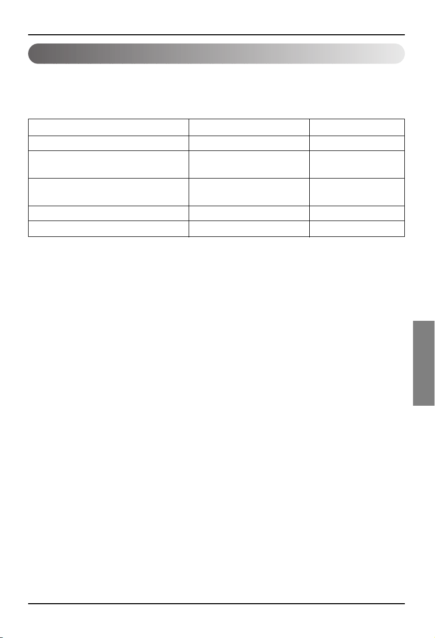
Diagramme de l’installation électrique externe
Manuel d’Installation 9
FRANÇAIS
1. Spécification de la ligne de communication RS-485 : 0.75mm2 ou plus de 2C shield, produit par
produit : 200M, longueur : 1km.
2. Ligne de communication FT-10 : consultez le tableau suivant
* Distance de la tête au noeud (max) : 250m, distance maximale : 450m
* AWG : American Wire Gauge (Calibre métallique)
Type de câble
Epaisseur de ligne (AWG)
Diamètre
TIA 568A Category 5 cable 24 0.5mm
Belden 88471 (PVC jacket) or 16 1.3mm
equivalent cable
Belden 85102(Tefzel jacket) or 16 1.3mm
equal cable
Level IV cable 22 0.65mm
JY(st)Y 2x2x0.8 20.4 0.8mm
Spécification de la ligne de communication
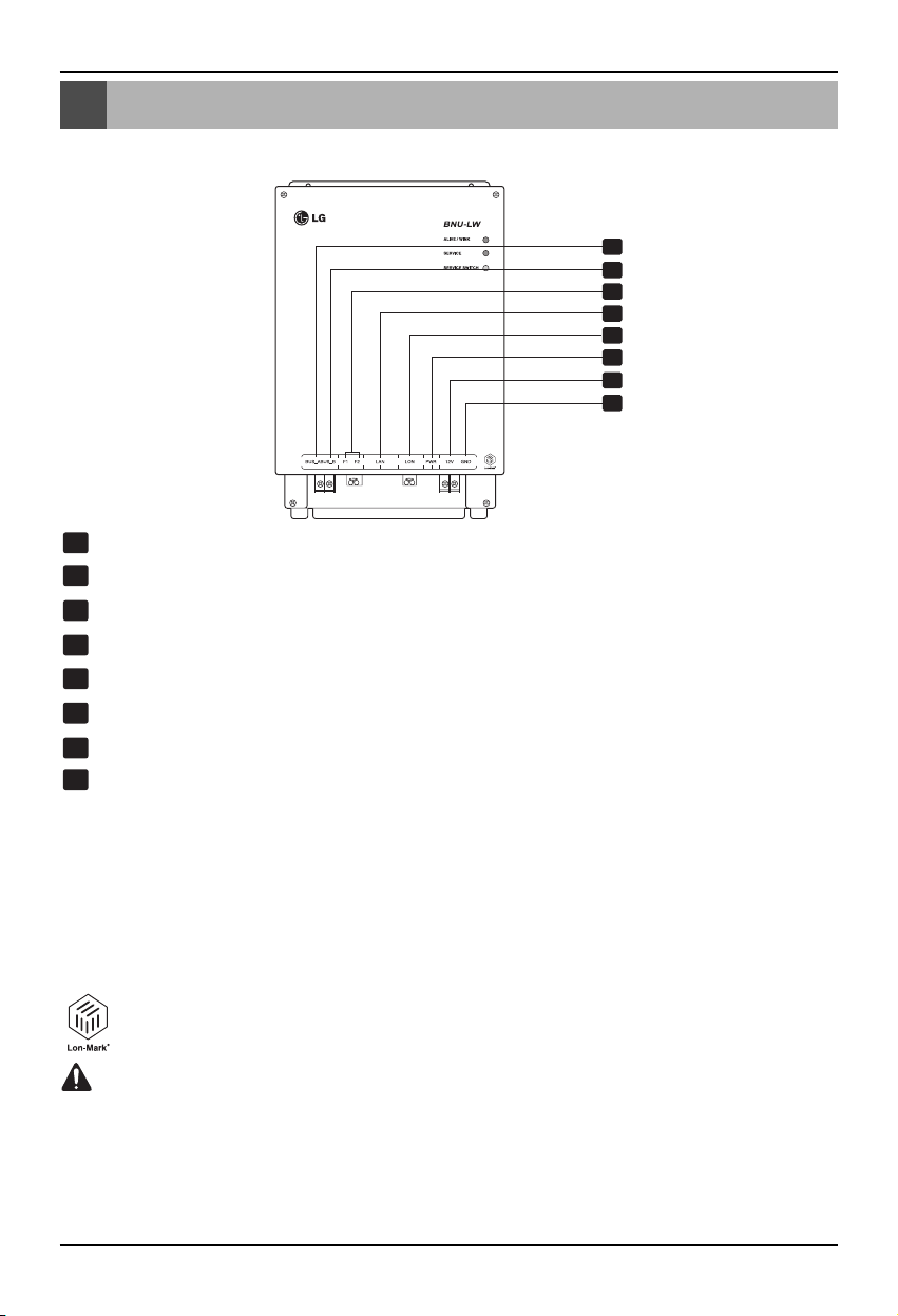
Nom de chaque partie
10 Lonworks Gateway
Nom de chaque partie
1
2
3
4
5
6
7
8
BUS_A : 485 ligne de communication A (+)
BUS_B : 485 ligne de communication B (-)
F1, F2 : Fonction de détection de feu (appareil externe) connexion du point de contact
LAN : port LAN nécessaire pour la fonction réseau
LON :
ligne de communication TP/FT-10 (ligne de communication du système Lonworks) non polarité
PWR : connexion à un convertisseur de puissance DC 12V.
12V : Connexion lors de la non utilisation du convertisseur de puissance DC 12V
GND: Connexion lors de la non utilisation du convertisseur GNS
ALIVE/WINK : il scintille toutes les secondes lorsqu’il est normal
Il scintille 5 fois lorsqu’il reçoit une commande WINK du système Lonworks (Vert)
SERVICE :il est éteint quand il est normal et il scintille lorsqu’il n’est pas connecté au
système Lonworks.
Il est allumé quand le commutateur de service est pressé.
COMMUTATEUR DE SERVICE : quand vous pressez le commutateur, l’ID (identité) de
la Neurone est transmise au système Lonworks, et le service LED est mis en marche.
Le produit BNU-LW (PNF-B16A1) est un produit certifié de LonMark, une norme
internationale.(LonMark Version 3.3)
1
8
2
3
4
5
6
7
Lonworks gateway
Les numéros 6, 7 et 8 sont pour l’alimentation. Cependant, il faut utiliser seulement une des
deux combinaisons.
Si vous utilisez du DC 12V pour l’alimentation, branchez No. 6 à l’alimentation (pas besoin
d’utiliser No. 7 et 8).
Si vous N’UTILISEZ PAS de DC 12V pour l’alimentation, branchez les No. 7 et 8 à
l’alimentation (pas besoin d’utiliser No. 6).
AVERTISSEMENT
Schéma d’installation
Manuel d’Installation 11
FRANÇAIS
Schéma d’installation
1. Installez le produit selon le mode de la télécommande centrale de l’appareil en salle et le DIP S/W
de PI485. (Mettez en marche (ON) le commutateur DIP No. 4)
(Consultez le manuel d’installation du PI485 pour plus de détails).
2. Connectez le BUS_A et le BUS_B (ligne de communication 485)
(Consultez la page suivante).
3. LON (TP/FT – ligne 10‡Lonworks Gateway connexion de la ligne de communication) ligne de
communication TP/FT-10 n’a pas de polarité.
Connectez les deux lignes de communication à BMS.
4. PWR (puissance supérieure)
Vous pouvez sélectionner juste une des deux pour une puissance supérieure.
Utilisez un convertisseur de puissance DC 12V
Connectez à No. 6 dans le nom de chaque partie.
Quand le DC12 séparé peut être fourni
Connectez le 12V et le GND aux terminaux No. 7 et 8.
5. Quand vous pressez le commutateur de service après la connexion au système Lonworks, le
service LED est mis en marche et l’ID du neurone est automatiquement transmis au système
Lonworks.
6. Vérifiez que le service LED est en conditions normales (OFF) au bout de 10 minutes. Si le service
LED est en conditions normales, alors l’installation a été bien faite.
7. Lors de l’utilisation du port de détection de feu, connectez les deux terminaux du senseur de feu à
F1 et F2. (Le senseur de détection de feu doit être utilisé par un DC producteur de 12V ou moins).
8. Après installation, connectez le câble LAN entre les ordinateurs pour utiliser le serveur Web et ainsi
vérifier que le produit LG a été installé normalement. – Consultez la partie des fonctions de
diagnose à distance (page 16) pour plus de détails.
Quand vous connectez la ligne de signal au terminal du Lonworks Gateway, utilisez
toujours un conducteur manuel.
(Il faut faire très attention à ne pas endommager le bloc terminal et le PCB).
PRÉCAUTION
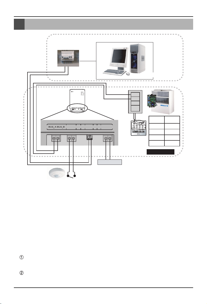
Schéma de l’installation électrique BNU-LW
12 Lonworks Gateway
Schéma de l’installation électrique BNU-LW
A
B
+10V
GND
TP/FT-10
Adaptateur
Lon Works
Puissance
Contrôle NMS (PC)
Senseur de détection de feu
(Utilisez le DC 12V ou moins)
F1 F2 LAN LON PWR 12V GND
Terminal
PI485
Télécommande
centrale
PI485
VOC
GND
C
D
10V
GND
BUS_A
BUS_B
LG ne fournit pas cette section (connexion et installation)
Fourni par LG
[Schéma de l’installation
électrique]
1. Connectez la ligne de communication 485
- Faites attention aux polarités du BUS A et
du BUS B(Consultez le manuel G/W pour
l’information DIP S/W pour 485 G/W).
2. Connectez la ligne de communication
Lonworks (TP/FT-10)
- Pas de polarité.
3. Puissance supérieure (Sélectionnez l’un des
No. 1 ou 2)
Utilisez un convertisseur DC 12V
- Connectez à No. 6 crics du nom de
chaque partie.
DC 12V supérieur pour l’installation du site.
- Connectez le 12V et le GND aux
terminaux No. 7 et 8.
4. Interface avec la télécommande centrale
simple.
- Mettez en marche (ON) le DIP S/W No. 2 de
la télécommande centrale simple et
configurez le marque selon la direction
rotative S/W).
(Consultez la partie de marque pour la
connexion à la télécommande centrale
simple (page 20) pour plus de détails).
5. Connectez le senseur de détection de feu
- Quand le signal de DC 12V ou moins est
transmis sur la case de feu, l’appareil en
salle et le produit de ventilation connectés au
BNU-LW seront tous arrêtés.
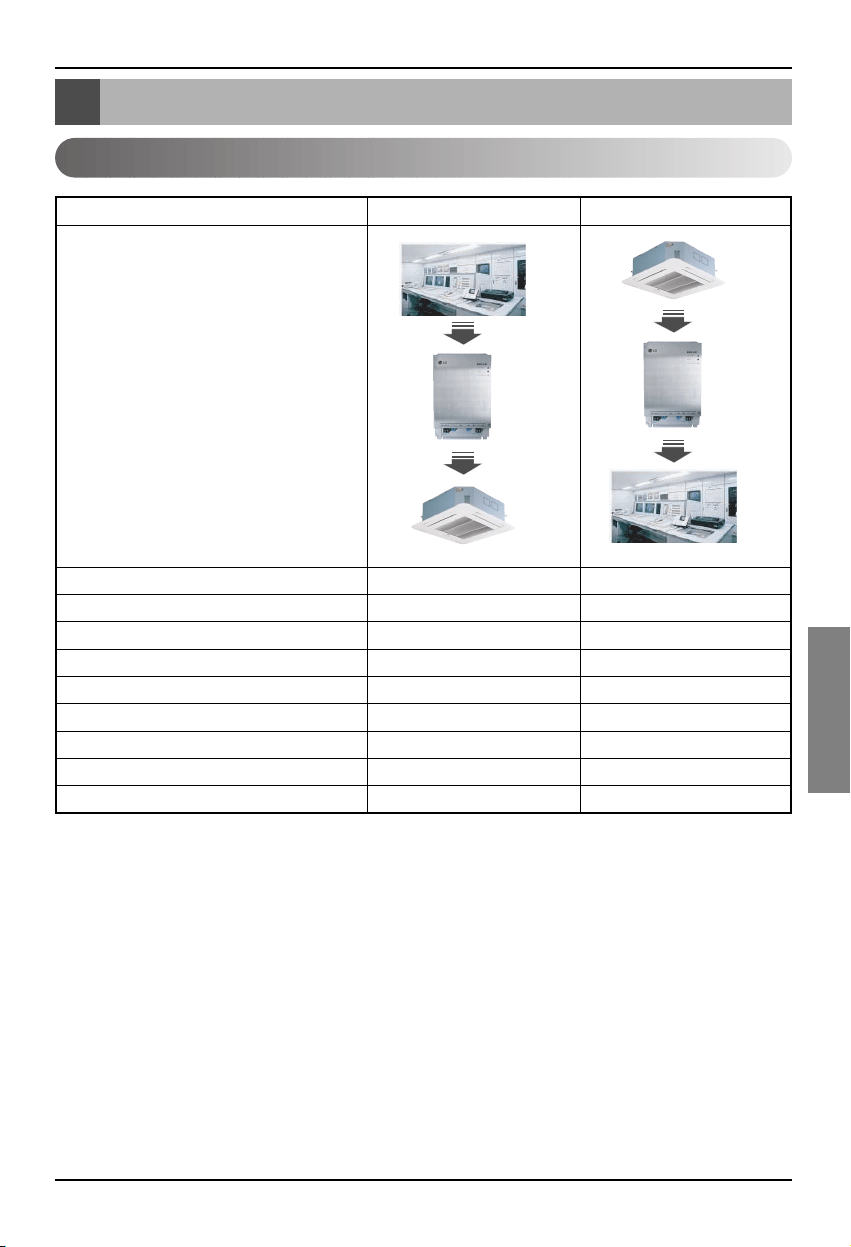
Tableau des fonctions de l’air conditionné/ventilation
Manuel d’Installation 13
FRANÇAIS
Tableau des fonctions de l’air conditionné/ventilation
Fonctions d’air conditionné de l’appareil en salle
Télécommande individuelle de l’appareil en salle
OO
Changement du mode de fonctionnement
OO
Changement du niveau d’aération O O
Fonction de réglage de température O O
Fonction de sécurité OO
Direction automatique d’aération O O
Vérification de la température de l’appareil en salle
XO
Vérification échouéeXO
Marche/arrêt simultanésOX
Fonction
BMS
BNU-LW
Air conditioner
BMS
BNU-LW
Air conditioner
Classification Contrôle Monitorage
Fonction de liaison (connexion) : la fonction de liaison apparaît quand l'output (sortie) d'une unité a été
liée à l’input (entrée) d'une autre unité et le processus d’input change
d’après le changement de l’output. La fonction de liaison est
praticable avec l'unité Lon d'un autre fabricant.
Ex) Quand l’output ON/OFF de l’appareil en salle No.1 est lié à l’input ON/OFF de l’appareil en salle
No. 2, et que l’appareil en salle No.1 est mis en marche, l’appareil en salle No.2 est aussi mis en
marche suite à la réception du signal.

Tableau des fonctions de l’air conditionné/ventilation
14 Lonworks Gateway
Fonction d’air conditionné de l’appareil en salle
Télécommande individuelle de l’appareil en salle
OO
Changement du mode de fonctionnement
OO
Changement du niveau d’aération O O
Utilisation du mode de fonctionnement
OO
(Ventilation rapide, puissance soutenue, chauffage)
Fonction de sécurité OO
Vérification échouéeXO
Marche/arrêt simultanésOX
Fonction
BMS
BNU-LW
Ventilation
BMS
BNU-LW
Ventilation
Classification Contrôle Monitorage
Fonction de liaison (connexion) : la fonction de liaison apparaît quand l’output d'un appareil a été lié à
l’input d'un autre appareil et le processus d’input change d’après le
changement de l’output. La fonction de liaison est praticable avec
l’appareil Lon d'un autre fabricant.
Ex) Quand l’output ON/OFF de l’appareil en salle No.1 est lié à l’input ON/OFF de l’appareil en salle
No. 2, et que l’appareil en salle No.1 est mis en marche, l’appareil en salle No.2 est aussi mis en
marche suite à la réception du signal.
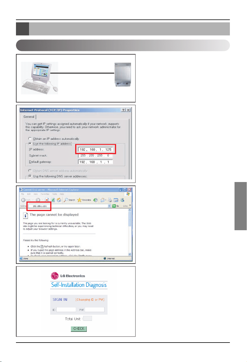
Fonctions de diagnose à distance BNU-LW
Manuel d’Installation 15
FRANÇAIS
1. Connectez la ligne LAN entre
l’ordinateur et le port LAN du BNU-LW.
2. Mettez le réseau IP de l’ordinateur
utilisé à 192.168.1xxx (sauf 101).
3. Tapez 192.168.1.101 sur Internet
Explorer.
4. Quand la connexion est normale, le
texte qui suit est montré.
• ID initiale : lonwork
• Mot de passe initial : lonwork
• Tapez le chiffre total d’appareils en
salle connectés sur le bloc Total Unit.
Fonctions de diagnose à distance BNU-LW
Méthode de fixation
LAN(cross cable)

Fonctions de diagnose à distance BNU-LW
16 Lonworks Gateway
Configuration
• Après avoir tapé l’ID et le mot de
passe, les produits d’air conditionné
et de ventilation connectés
actuellement sont affichés sur la
photo.
• La partie « A » montre le nombre
de produits d’air conditionné et de
ventilation connectés actuellement.
• Si vous voulez contrôler un produit.
➀ Sélectionnez le produit - ➁
Mettez la direction – ➂Commandez
ON/OFF – ➃ Sélectionnez le mode
- ➄ Cliquez sur Vérification pour
contrôler le produit.
• Si vous voulez vérifier le statut ➅
courent cliquez sur Reload
(Recharger) et vous serez en
mesure de vérifier le statut courent
de l’appareil en salle sur la partie «
B ».
• Si vous voulez changer l’ID, cliquez
sur [Set up Network place] pour
changer l’ID.
"A"
"B"
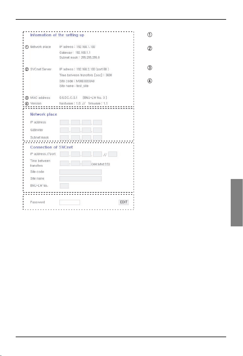
Fonctions de diagnose à distance BNU-LW
Manuel d’Installation 17
FRANÇAIS
A
B
C
D
A: Il affiche les données masquées de
l'IP actuel, le Gateway, le Subnet.
Si vous voulez utiliser le Serveur
SVCnet, il affiche les données du
Serveur SVCnet.
Il affiche les données des adresses
MAC.
Il affiche la version courante des
données du BNU-LW.
B: Si vous voulez changer les données
masquées de l’IP et le Gateway, le
Subnet, cliquez sur le bouton Edit à
côté des données que vous voulez
changer.
C: C'est un espace pour taper les
données de connexion du serveur
SVCnet. Le serveur SVCnet est le
service qui fait le monitorage de statut
d’air conditionnés connectés au BNU-
LW à travers le LAN dans l’avenir par
LG Electronics Service Center pour
fournir une notification rapide en cas
de problème.
D: Pour prévenir le réseau ou le
changement arbitraire, une fonction
pour votre sécurité fut appliquée : il
faut taper le mot de passe d'ouverture
de session pour changer la fixation du
réseau.
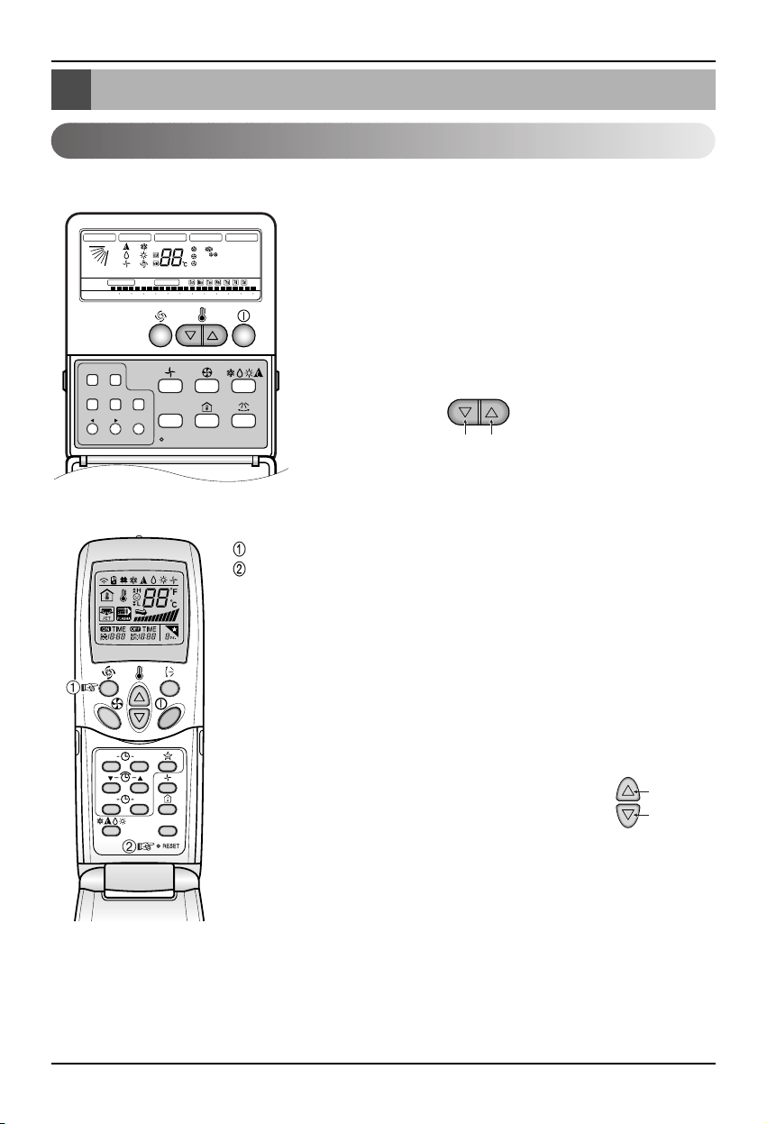
Fixation de l’adresse de l’appareil en salle
18 Lonworks Gateway
Fixation de l’adresse de l’appareil en salle
Fixation de l’adresse de l’appareil en salle
Lors de l’utilisation de la télécommande câblée
Lors de l’utilisation de la télécommande sans fil
Timer Cancel
Program Week
Hour Min
Holiday
Set/Clr
RESET
ZONE
1234
Operation unit
Humidify
JET
AUTO
AUTO SWING OPERATION
FAN SPEED
Program set
SUB FUNCTION
SET TEMP
Room Temp
HI
MED
LO
Heater
Defrost
Filter
Preheat
Out door
Time
Timer
On
Set no. Time
Off
01 03 05 07 09 11 13 15 17 19 21 23
Plasma
ON OFF
SET
CANCEL
PLASMA
Groupe No. Appareil en salle No.
Réglage de température
1. Pressez les boutons set/cancel du jour de semaine et de la
réservation simultanément pendant 3 secondes.
2. En utilisant le bouton de réglage de la température, mettez
l’adresse de l’appareil en salle.
Fixation de gamme : 00~FF
3. Quand vous pressez les boutons set/cancel du jour de la
semaine et de la réservation simultanément pendant 3
secondes, la fixation de l’adresse est complète.
Mode de fixation d’adresse
1. Appuyez sur la touche du haut à gauche pendant plus de 3 secondes.
Pendant que vous appuyez sur la touche du haut à gauche, appuyez sur la
touche de réinitialisation.
❈
Les télécommandes sans fils ont des formes qui varient selon le modèle.
2. En utilisant le bouton de réglage de température, mettez l’adresse de l’appareil en
salle.
Fixation de gamme : 00~FF
3. Après avoir marqué l’adresse, pressez une fois le bouton ON/OFF vers l’appareil en
salle.
4. L’appareil en salle affichera l’adresse marquée pour compléter la fixation d’adresse.
(Le temps et la méthode d’adresse affichée peuvent varier
selon le type d’appareil en salle).
5. Fixez de nouveau la télécommande pour utiliser le mode de
fonctionnement général.
Mode de verification d’adresse
1. With the top right button pressed, press the Reset button.(Press the left
button for more than 3 seconds.)
2. Press the ON/OFF button toward the indoor unit 1 time, and the indoor
unit will display the set address in the display window. (The address
display time and method can differ by the indoor unit type.)
3. Reset the remote controller to use the general operation mode.
❈ Cette fonction peut ne pas marcher pour certaines télécommandes selon la date de fabrication de
la télécommande câblée/sans fil.
Ceci n’est point important pour l’utilisation et vous pouvez mettre l'adresse avec une télécommande
qui ait la fonction de fixation d’adresse pendant l'installation.
Groupe No.
Appareil en
salle No.
Réglage de
température
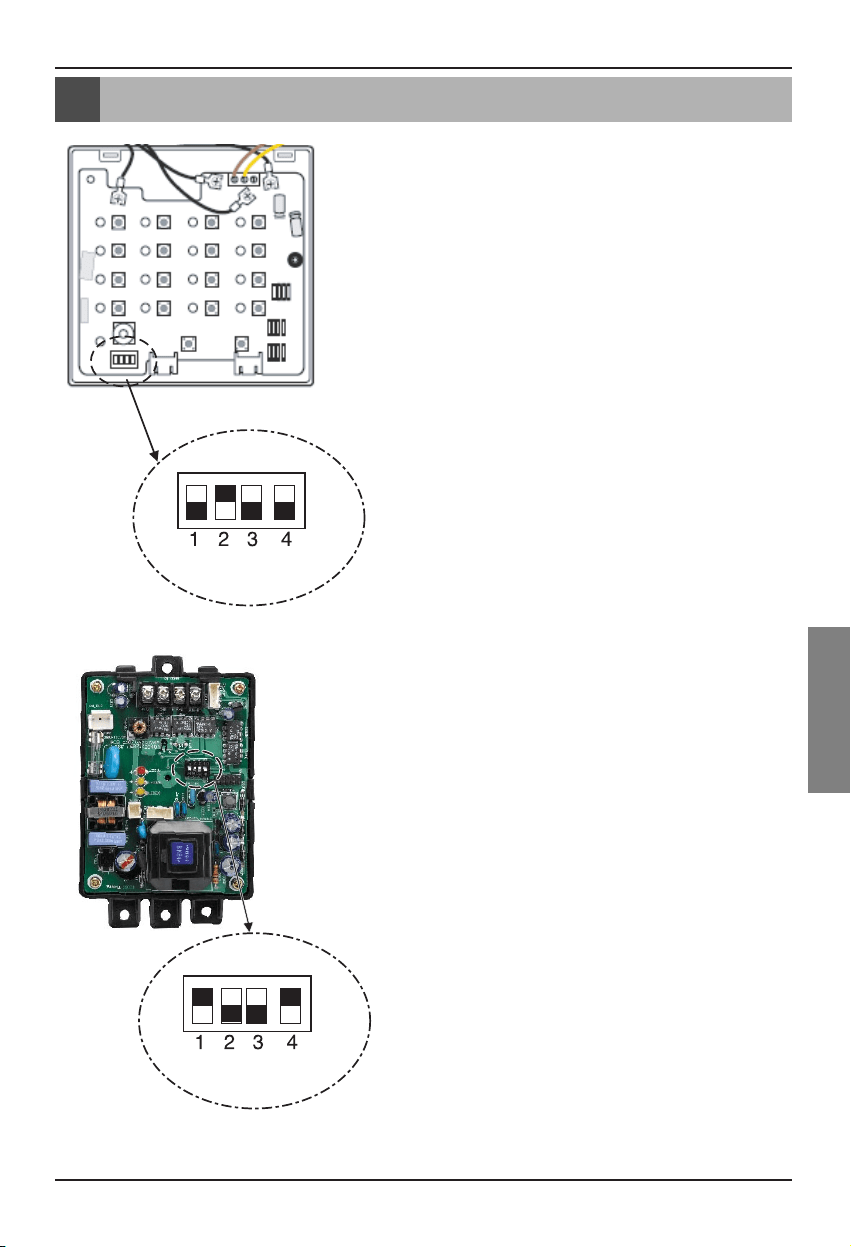
Interface avec la télécommande centrale simple.
Manuel d’Installation 19
FRANÇAIS
Interface avec la télécommande centrale simple.
Comment faire l’Interface avec une
télécommande centrale simple
• Pour l’Interface avec une télécommande centrale simple,
mettez en marche le DIP S/W No. 2 de la télécommande
centrale simple.
• Mettez le S/W rotatif pour le group d’adresse de l’appareil en
salle que vous voulez contrôler.
Comment fixer le PI-485
Comment fixer le PI-485
• BNU-LW utilise le protocole de communication LGAP
Vous pouvez mettre en marche le DIP S/W No.1 et No.4 du
PI-485.

Annexe
20 Lonworks Gateway
Annexe
Objets A/C
• L’annexe porte les renseignements nécessaires pour faire l’interface avec BMS et non nécessaires
pour l'installation actuelle.
Blocage Fonction Standard
SCC(8500)FB
Variables du
réseau des unités
intérieures /
extérieures
SNVT
_
switch nviOnOff
SNVT
_
hvac
_
mode nviHeatCool
SNVT
_
switch nviFanSpeedcmd
SNVT
_
switch nviLock
SNVT
_
switch nviSwing
SNVT
_
switch nviSetPoint
SNVT
_
switch nviUser
SNVT
_
switch nviSpaceTemp
SNVT
_
switch nvoOnOff
SNVT
_
hvac
_
mode nvoHeatCool
SNVT
_
switch nvoFanSpeed
SNVT
_
switch nvoLock
SNVT
_
switch nvoSwing
SNVT
_
temp
_
P nvoSetPoint
SNVT
_
hvac
_
status nvoUnitStatus
SNVT
_
count nvoUser
SWITCH(3200)FB
Contrôle
Total
SNVT
_
switch
nviTotalOnOff
_
Indoor
SNVT
_
switch
nviTotalOnOff
_
Vent
SNVT
_
switch nvoSwitch
• Vous pouvez permettre le contrôle et le monitorage comme il est montré dans la figure pour un
appareil d’air conditionné/ventilation.
• La variable du réseau peut différer de celle en cours.
(Consultez le dossier XIF pour la variable correcte de réseau.)
Contrôle Monitorage
Commande ON/OFF
Commande de sélection du mode
Commande de sélection du niveau d’aération
Commande de sécurité d’appareil en salle
Commande de direction d’aération
Commande de réglage de température
Commende de la fonction de ventilation additionnelle
(Applicable seulement aux produits de ventilation)
Contrôle ON/OFF de l’air conditionné total
Contrôle ON/OFF de ventilation totale
Monitorage du statut ON/OFF
Monitorage du statut de Mode
Monitorage du statut du niveau d’aération
Monitorage du statut de sécurité
Monitorage du statut d’adresse d’aération
Monitorage du statut de réglage de température
Monitorage de la température en cours
Affichage d’échec
Monitorage du statut de la fonction de ventilation
additionnelle
(Applicable seulement aux produits de ventilation)
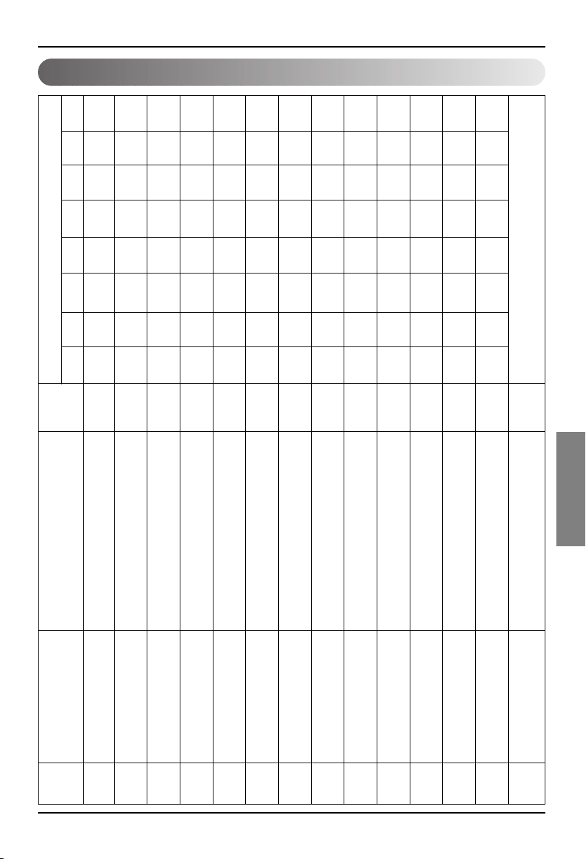
Annexe
Manuel d’Installation 21
FRANÇAIS
Point de contrôle/monitorage de l’air conditionné
1 ON/OFF (réglage) SNVT_switch nviOnOff_nn Entrée arrêter
Fonctionnement)
2 ON/OFF (statut) SNVT_switch nvoOnOff_nn Sortie arrêter
Fonctionnement)
3 Verrou (réglage) SNVT_switch nviLock_nn Entrée annuler
Fixation
4 Verrou (statut) SNVT_switch nvoLock_nn Sortie annuler
Fixation
5
Mode de Fonctionnement (réglage)
SNVT_hvac_modenviHeatCool_nn Entrée
automatique
Chauffage
Refroidissement
Aération
anti-humidité
6
Mode de Fonctionnement (statut)
SNVT_hvac_mode nviHeatCool_nn Sortie
automatique
Chauffage
Refroidissement
Aération
anti-humidité
7 Balancer (statut) SNVT_switch nviSwing_nn Entrée annuler
Fixation
8 Balancer (réglage) SNVT_switch nvoSwing_nn Sortie annuler
Fixation
9
Vitesse Ventilateur (réglage)
SNVT_switch nviFanSpeedCmd_nn Entrée Bas
Moyen
Haut
automatique
Faible
10
Vitesse Ventilateur (statut)
SNVT_switch nvoFanSpeed_nn Sortie Bas
Moyen
Haut
automatique
Faible
11
Régler température ambiante
SNVT_temp_p nviSetPointCmd_nn Entrée °C
12
Régler température ambiante
SNVT_temp_p nvoSetPoint_nn Sortie °C
13 Température ambiante SNVT_temp_p nvoSpaceTemp_nn Sortie °C
14 Code erreur SNVT_hvac_status nvoUnitStatus_nn Sortie
Pas d’erreur Consultez le Code d’Erreur d'Air Conditionné LG.
Point
No.
Nom
Type
objet
Unité
code 0 code 1 code 2 code 3 code 4 code 5 code 9 code 14
Nom objet
(nn : Groupe d'air conditionnée et de
ventilation/adresse de l’appareil en salle)

Annexe
22 Lonworks Gateway
Point de contrôle/monitorage de ventilation
1 ON/OFF (réglage) SNVT_switch nviOnOff_nn Entrée arrêter
Fonctionnement
2 ON/OFF (statut) SNVT_switch nvoOnOff_nn Sortie arrêter
Fonctionnement
3 Verrou (réglage) SNVT_switch nviLock_nn Entrée annuler Fixation
4 Verrou (statut) SNVT_switch nvoLock_nn Sortie annuler Fixation
5
Mode de Fonctionnement (réglage)
SNVT_hvac_modenviHeatCool_nn Entrée
automatique
chauffage
Normal
6
Mode de Fonctionnement (statut)
SNVT_hvac_mode nviHeatCool_nn Sortie
automatique
chauffage
Normal
7
Vitesse Ventilateur (réglage)
SNVT_switch nviFanSpeedCmd_nn Entrée Bas Haut Très Haut
8 Vitesse Ventilateur (statut) SNVT_switch nvoFanSpeed_nn Sortie Bas Haut Très Haut
9 Erreur code SNVT_hvac_status nvoUnitStatus_nn Sortie Consultez le Code d’Erreur d'Air Conditionné LG.
10 Mode Utilisateur (réglage) SNVT_count nviUser_nn Sortie rapide
puissance soutenue
Chaud
11 Mode Utilisateur (statut) SNVT_count nvoUser_nn Sortie rapide
puissance soutenue
Chaud
Point
No.
Nom
Type
objet
Unité
code 0 code 1 code 2 code 3 code 5 code 9
Nom objet
(nn : Groupe d'air conditionnée et de
ventilation/adresse de l’appareil en salle)
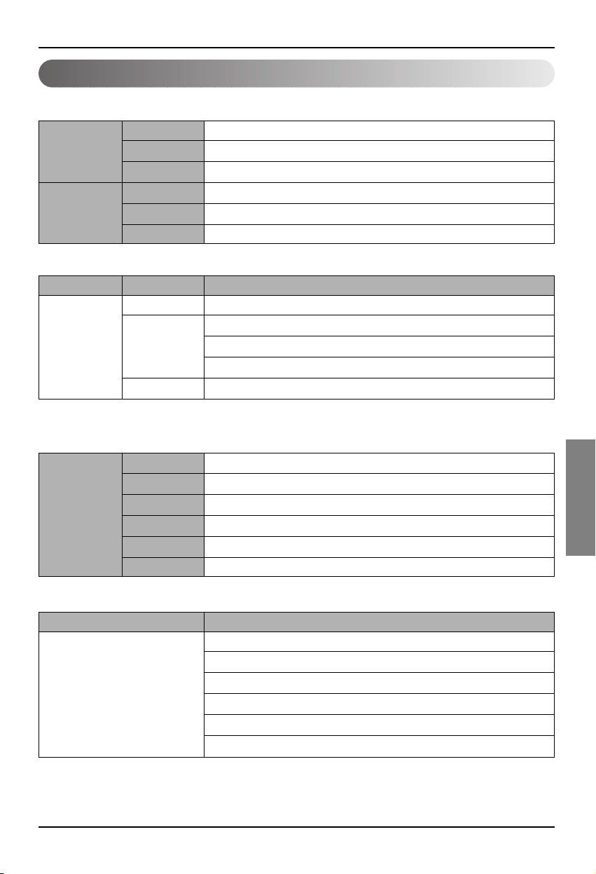
Annexe
Manuel d’Installation 23
FRANÇAIS
Variables de réseau
1) Individuel marche/arrêt input/output(Air conditionné/ventilation)
Gamme valable
Interrupteur_
SNVT
(index : 95)
NV Champ Fonctionnement
Fonction Marche/arrêt input
Input Utilisation de NV Variables de réseau input : SNVT_switch nviOnOff_n
Fonctionnement Il contrôle la marche/arrêt de chaque produit (air conditionné/ventilation)
Fonction Affichage du statut marche/arrêt
Output Utilisation de NV Variable de réseau output : SNVT_switch nvoOnOff_n
Fonctionnement
Ceci fait le monitorage du statut de fonctionnement de chaque produit (air conditionné/ventilation)
2) Mode de fonctionnement input/output(air conditionné/ventilation)
Fonction Commande input mode de fonctionnement
Input Utilisation de NV Variable de réseau input : SNVT_hvac_mode nviHeatCool_n
Fonctionnement
Il contrôle le mode de fonctionnement de chaque produit d’air conditionné/ventilation
Fonction Affichage du statut de mode de fonctionnement
Output Utilisation de NV Variable de réseau output : SNVT_hvac_mode nvoHeatCool_n
Fonctionnement
Ceci fait le monitorage du statut de fonctionnement de chaque produit d’air conditionné/ventilation
Valeur Non utilisé (réglé sur 0% manuellement)
0 = produit d’air conditionné/ventilation OFF
Etat 1 = produit d’air conditionné/ventilation ON
Valeur par défaut
HVAC_AUTO:0 = mode auto (auto), Ventilation automatique
HVAC_HEAT:1 = mode chaud (chaud), Ventilation chaude
HVAC_COOL: 3 = mode froid (froid)
HVAC_FAN_ONLY:9 = Mode Aération (fan), Ventilation normale
HVAC_DEHUMID:14 = Mode sec (anti-humidité)
Valeur par défaut
Gamme valable
Mode_hvac_SNVT
(index : 108)
NV Fonctionnement

Annexe
24 Lonworks Gateway
1 : Air conditionné, ventilation d’aération basse
2 : Air conditionné moyen, ventilation d’aération haute
Valeur 3 : Air conditionné haut, ventilation d’aération très haute
4 : Air conditionné, ventilation d’aération automatique
5 : Air conditionné d’aération très basse
Etat 0 : produit non applicable 1 : produit applicable
Valeur par défaut
3) Commande du niveau d’aération input/output (Air conditionné/ventilation)
Gamme valable
Interrupteur_
SNVT
(index : 95)
NV Champ Fonctionnement
Fonction Commande du niveau d’aération input
Input Utilisation de NV Variable de réseau input : SNVT_switc nviFanSpeedCmd_n
Fonctionnement Il contrôle le niveau d’aération de chaque appareil en salle.
Fonction Affichage du statut de niveau d’aération
Output Utilisation de NV Variable de réseau output : SNVT_switch nvoFanSpeed_n
Fonctionnement Il contrôle le niveau d’aération de chaque produit (Air conditionné/ventilation)
Valeur Non utilisé (réglé sur 0% manuellement)
0 = produit d’air conditionné/ventilation Sécurité OFF
Etat 1 = produit d’air conditionné/ventilation Sécurité ON
Valeur par défaut
4) Sécurité input/output (Air conditionné/ventilation)
Gamme valable
Interrupteur_
SNVT
(index : 95)
NV Champ Fonctionnement
Fonction Fixation de la commande input de sécurité
Input Utilisation de NV Variable de réseau input : SNVT_switch nviLock_n
Fonctionnement Il contrôle la sécurité de chaque produit (air conditionné/ventilation)
Fonction Affichage du statut de sécurité
Output Utilisation de NV Variable de réseau output : SNVT_switch nvoLock_n
Fonctionnement
Il fait le monitorage du statut de sécurité de chaque produit (air conditionné/ventilation)
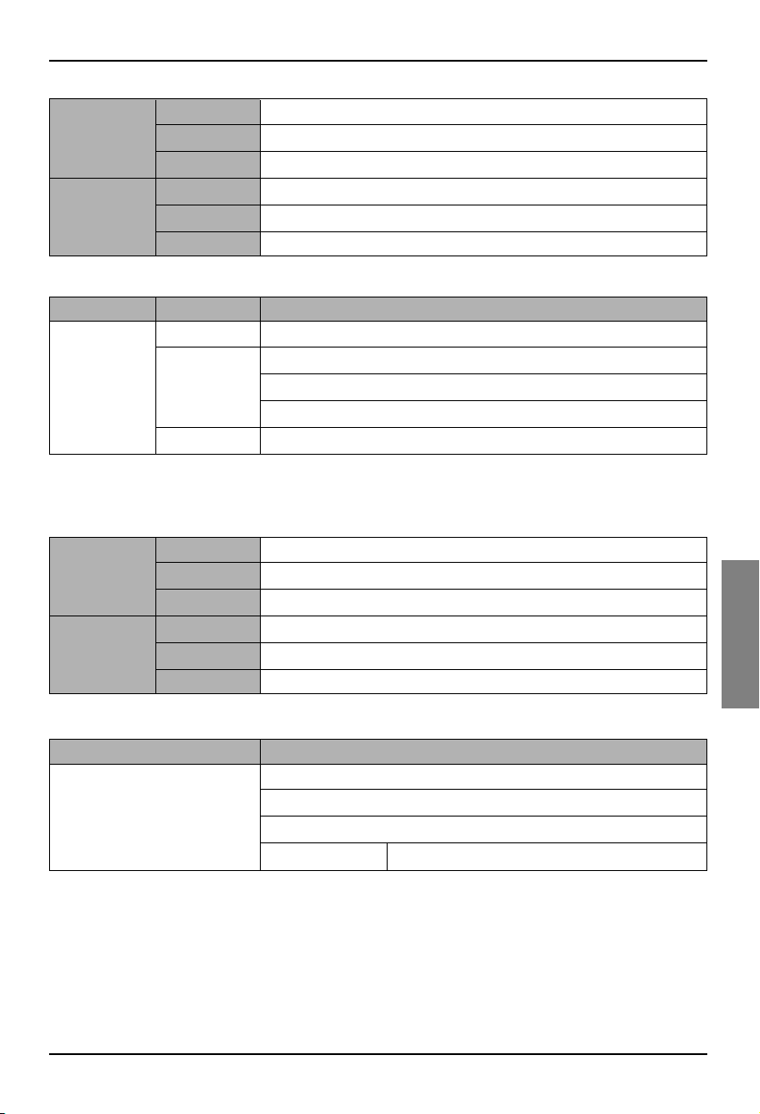
Annexe
Manuel d’Installation 25
FRANÇAIS
Valeur Non utilisé (réglé sur 0% manuellement)
0 = direction d’aération fixée pour le produit d’air conditionné
Etat 1 = direction d’aération auto pour le produit d’air conditionné
Valeur par défaut
5) Direction d’aération auto input/output (applicable seulement à l’air conditionné)
Gamme valable
SNVT_switch
( Index : 95 )
NV Champ Fonctionnement
Fonction Commande input d’aération auto
Input Utilisation de NV Variable de réseau input : SNVT_switch nviSwing_n
Fonctionnement
Il contrôle la direction d’aération de chaque produit (air conditionné/ventilation)
Fonction Affichage du statut de direction d’aération auto
Output Utilisation de NV Variable de réseau output : SNVT_switch nvoSwing_n
Fonctionnement
Il fait le monitorage de la direction d’aération de chaque produit (air conditionné/ ventilation)
6) Fixation de température input/output (applicable seulement à l’air conditionné)
Fonction Marque la gamme de température input
Input Utilisation de NV Variable de réseau input : SNVT_switch nviSetPoint_n
Fonctionnement
Il contrôle la température marquée de chaque produit (air conditionné/ventilation)
Fonction Affichage du statut de fixation de température
Output Utilisation de NV Variable de réseau output : SNVT_switch nvoSetPoint_n
Fonctionnement
Il fait le monitorage de fixation de température de chaque produit (air conditionné/ ventilation)
En mode Froid : entre 18 et 30 C
En mode Chaud : entre 18 et 30 C
En mode Sec et Ventilateur : Non disponible.
Valeur par défaut
Gamme valable
Interrupteur_SNVT
(index : 95)
NV Fonctionnement
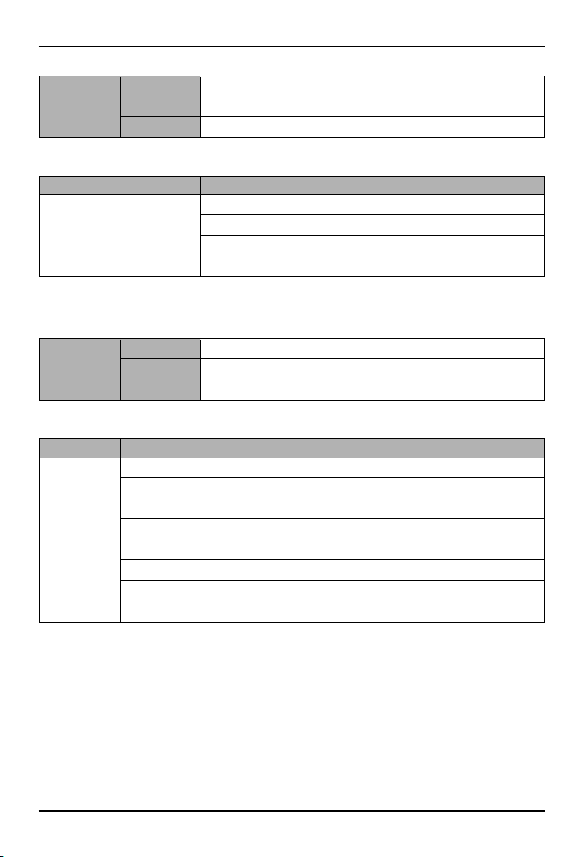
Annexe
26 Lonworks Gateway
7) Affichage du statut de température de la salle (applicable seulement à l’air conditionné)
Fonction Affichage du statut de température de la salle
Output Utilisation de NV Variable de réseau output : SNVT_switch nvoSpaceTemp_n
Fonctionnement Il fait le monitorage de la température de la salle
8) Erreur output (air conditionné/ventilation)
Fonction Affichage du statut d’erreur
Output Utilisation de NV Variable de réseau output : SNVT_hvac_Status nvoUnitStatus_n
Fonctionnement
Il fait le monitorage du statut d’erreur de chaque produit (air conditionné/ventilation)
En mode Froid : entre 10 et 40 C
En mode Chaud : entre 10 et 40 C
En mode Sec et Ventilateur : Non disponible.
Valeur par défaut
Valid Range
Interrupteur_SNVT
(index : 95)
NV Fonctionnement
Mode Affichage du mode de fonctionnement en cours
Sortie_chaleur_premier Non utilisé
Sortie_chaleur_Second Non utilisé
Sortie_froid Non utilisé
Sortie_froid Non utilisé
Sortie_Economie Non utilisé
Sortie_ventilateur Non utilisé
Sortie_In Affichage du Code d’Erreur
Valid Range
SNVT_switch
( Index : 112 )
NV Champ Fonctionnement
* Consultez le tableau de Code d’Erreur sur le manuel du produit pour l’erreur de code.
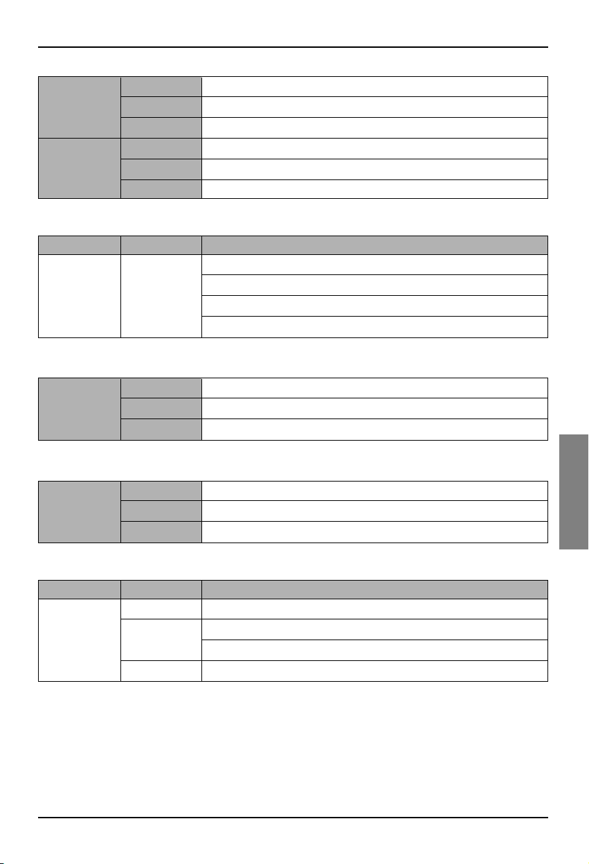
Annexe
Manuel d’Installation 27
FRANÇAIS
10) Total marche/arrêt d’appareils en salle d’air conditionné
Fonction Total de commandes arrêt input
Input Utilisation de NV Variable de réseau input : SNVT_switch nviTotalONOFF_indoor
Fonctionnement Il change en ON ou OFF tous les appareils en salle.
11) Total marche/arrêt d’appareils en salle de ventilation
Fonction Total de commandes arrêt input
Input Utilisation de NV Variable de réseau input : SNVT_switch nviTotalONOFF_indoor
Operation Il change en ON ou OFF tous les appareils de ventilation.
0 = Non utilisé
Valeur
1 = Mode rapide
2 = Mode économie d’énergie
3 = Chaud
9) Commande de fonction de ventilation (applicable seulement aux produits de ventilation)
Valid Range
Compteur_
SNVT
(index : 8)
NV Filed Fonctionnement
Fonction Input mode de fonctionnement de ventilation
Input Utilisation de NV Variable de réseau input : SNVT_count nviUser_n
Fonctionnement Il contrôle la fonction de production de chaque produit de ventilation.
Fonction Statut de mode de fonctionnement de ventilation
Output Utilisation de NV Variable de réseau output : SNVT_count nvoUser_n
Fonctionnement Il fait le monitorage du statut de fonction de chaque produit de ventilation.
Valeur Non utilisé
Etat
1 = Unité intérieure/ventilateur sur ON
0 = Unité intérieure/ventilateur sur OFF
Valeur par défaut
Valid Range
SNVT_switch
( Index : 95 )
NV Filed Fonctionnement

Note
28 Lonworks Gateway

DEUTSCH
LG
BNU-LW(Lonworks Gateway)
LG
WICHTIG
• Lesen Sie diese Anleitung vor der Montage des
Gerätes sorgfältig durch.
• Bewahren Sie dieses Benutzerhandbuch nach
sorgfältigem Lesen auf.
Montageanleitung

2 Lonworks Gateway
BNU-LW (Lonworks Gateway)
INHALTSVERZEICHNIS
Sicherheitshinweise...............................................................................................3
Gesamt-Systemdiagramm.....................................................................................7
Externer Anschlussschaltplan..............................................................................8
Einstellen der Adresse für die mit der BNU-LW (Lonworks Gateway)
verbundenen Zentralsteuerung des Innengeräte................................................8
Communication line specification .......................................................................9
Bauteilbezeichnungen.........................................................................................10
Montagefolge........................................................................................................11
BNU-LW Anschlussfolge .....................................................................................12
Funktionstabelle Klimagerät/Belüftug ...............................................................13
Innengerätefunktion ..........................................................................................13
Belüftungsfunktion Innengerä ...........................................................................14
Ferndiagnosefunktion des BNU-LW...................................................................15
Einstellungsmöglichkeiten.................................................................................15
Konfiguration.....................................................................................................16
Einstellung der Innengeräte-Adresse ................................................................18
Einstellung der Innengeräte-Adresse ...............................................................18
Verbindung mit der einfachen Zentralsteuerung ..............................................19
Anhang..................................................................................................................20
Klimageräteobjekt .............................................................................................20
Air conditioner control/monitoring point ............................................................21
Ventilation control/monitoring point...................................................................22
Netzwerkvariablen ............................................................................................23
Sicherheitshinweise
Montageanleitung 3
DEUTSCH
Das Gerät darf nicht durch
Anschließen oder Ziehen
des Netzsteckers
eingeschaltet
oder ausgeschaltet werden.
• Durch Wärmeerzeugung
können Stromschläge
oder Brände verursacht
werden.
Wenden Sie sich bei
Fragen zu den Geräten
an einen Servicebetrieb
oder an einen Montage-
Fachbetrieb.
•
Ansonsten besteht Unfall-
,Stromschlag-, Explosions-
oder Verletzungsgefahr.
Verwenden Sie nur
Standard-Teile.
•
Ansonsten besteht die
Gefahr von Stromschlägen,
Explosionen, Verletzungen
oder Ausfällen.
■ Betrieb
BNU-LW
BNU-LW
Sicherheitshinweise
Um Verletzungen des Benutzers oder anderer Personen sowie Sachbeschädigungen zu
vermeiden, müssen die folgenden Anleitungen befolgt werden.
■
Bei unsachgemäßer Bedienung und Missachtung der Anleitungen besteht die Gefahr von Verletzungen
oder Sachschäden. Der Grad der Gefährdung wird durch folgende Symbole gekennzeichnet.
■ Die Bedeutung von Symbolen in diesem Handbuch lauten wie folgt.
ACHTUNG
VORSICHT
Dieses Symbol bedeutet Lebensgefahr oder Gefahr schwerer Verletzungen.
Dieses Symbol bedeutet Verletzungsgefahr oder Gefahr von Sachbeschädigungen.
Darf nicht ausgeführt werden.
Die Anleitung sollte befolgt werden.
ACHTUNG
Standard-Bauteile
Sicherheitshinweise
4 Lonworks Gateway
Falls Wasser in das Gerät eindringt, schalten
Sie den Hauptschalter des Gerätes aus.
• Ziehen Sie den Netzstecker von der
Steckdose und setzen Sie sich mit Ihrem
Servicebetrieb in Verbindung.
Das Gerät darf nicht in feuchten
Umgebungen betrieben werden.
• Wasser kann in die Anlage eindringen
und die Isolierung beschädigen.
Es besteht Stromschlaggefahr.
BNU-LW
BNU-LW
■ Während des Betriebs
Verständigen Sie bei einer
Neumontage des Gerätes
einen Servicebetrieb oder
oder einen Montage-
Fachbetrieb.
•
Ansonsten besteht Unfall-
,Stromschlag-, Explosions-
oder Verletzungsgefahr.
Das Netzkabel darf nicht in
der Nähe von brennbaren
Gasen oder Flüssigkeiten wie
z. B. Benzin, Benzol oder
Verdünner verwendet werden.
•
Es besteht Explosionsgefahr
oder Brandgefahr.
Das Gerät darf nicht wahllos
demontiert, repariert oder
verändert werden.
• Ansonsten besteht Brand-
und Stromschlaggefahr.
BNU-LW
BNU-LW
Wax
Thinner
BNU-LW
Das Netzkabel darf nicht
wahllos verlängert oder
verändert werden.
• Ansonsten besteht Brand-
und Stromschlaggefahr.
Die Netzkabel dürfen nicht
überkreuzt angeordnet
werden.
• Ansonsten besteht Brand-
und Stromschlaggefahr.
Ziehen Sie den Netzstecker, falls
ungewöhnliche Geräusche, Gerüche
oder Rauch vom Gerät ausgehen.
• Ansonsten besteht Brand-
und Stromschlaggefahr.
BNU-LW
Sicherheitshinweise
Montageanleitung 5
DEUTSCH
Keine Schusswaffen in der
Nähe des Gerätes lagern.
• Es besteht Brandgefahr.
Das Gerät niemals in der Nähe
von elektrischen Lüftern oder
Heizungen betreiben.
• Ansonsten besteht Brand-
und Stromschlaggefahr.
Es darf kein Wasser in das
Gerät eindringen.
•
Ansonsten besteht die
Gefahr von Stromschlägen
oder Geräteausfällen.
BNU
-LW
BNU-LW
BNU-LW
Keine schweren
Gegenstände auf das Gerät
stellen.
• Ansonsten besteht Brand-
und Stromschlaggefahr.
Der Netzstecker muss beim
Abziehen von der Steckdose
am Netzstecker selbst
gehalten werden.
• Es besteht die Gefahr von
Strom-schlägen oder
Sachbeschädigungen.
Keine schweren
Gegenstände auf das Gerät
stellen.
•
Das Gerät könnte ausfallen.
BNU-LW
BNU-LW
Verständigen Sie bei
Eindringen von Wasser in
das Gerät einen
Servicebetrieb oder einen
Montage-Fachbetrieb.
•
In diesem Fall ist der
Benutzer zur Vermeidung vor
Bränden und Stromschlägen
verantwortlich.
Das Gerät darf nicht von
Kindern betrieben werden.
• Es besteht Unfallgefahr
sowie die Gefahr von
Geräteausfällen.
Vermeiden Sie starke
Erschütterungen des
Gerätes.
•
Erschütterungen und somit ein
mögliches Herunterfallen des
Gerätes müssen vom
Benutzer verhindert werden.
BNU-LW
BNU-LW
BNU-LW

Sicherheitshinweise
6 Lonworks Gateway
■ Während des Betriebs
VORSICHT
Verwenden Sie zur
Reinigung des Gerätes nur
ein weiches Tuch.
• Ansonsten könnte das
Gerät Feuer fangen oder
beschädigt werden.
Keine Tiere oder feuchte
Pflanzen auf das Gerät
stellen.
• Das Gerät könnte
ausfallen.
Verwenden Sie nur einen
empfohlenen Adapter.
• Ansonsten könnte das
Gerät ausfallen.
BNU-LW
Wax
Thinner
BNU-LW
BNU-LW
Einen Kontakt, auch kurzzeitig,
mit Metallgegenständen
vermeiden, wie z. B.
Halsketten, Münzen, Schlüssel,
Armbanduhren mit Batterie.
• Es besteht die Gefahr von
Geräteausfällen und
Verletzungen.
Der Netzstecker muss beim
Herausziehen von der
Steckdose am Netzstecker
selbst gehalten werden.
• Es besteht die Gefahr von
Strom-schlägen oder
Sachbeschädigungen.
BNU-LW
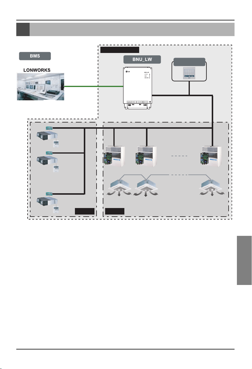
Gesamt-Systemdiagramm
Montageanleitung 7
DEUTSCH
Gesamt-Systemdiagramm
Einfache
Zentralsteuerung
Belüftung Klimagerät
485-Verbindung
* Zur Verbindung mit bis zu 64 Innengeräten (Belüftung+Klimagerät)
LG Geräte
* PNF-B16A1 (Lon Gateway) can be used in connection with the simple central
controller.

Externer Anschlussschaltplan
8 Lonworks Gateway
LON-Protokoll
BMS system
BNU-LW
RS485
RI485
Adresse der Zentralsteuerung(0.0)
(0.1)............(0.F)
Adresse der Zentralsteuerung(1.0)
Adresse der
Zentralsteuerung(2.0)
Adresse der
Zentralsteuerung(2.4)
(2.1) (2.2) (2.3)
(2.5) (2.6) (2.7)
(1.1)............(1.F)
Klimagerät
RI485
<Maximale Anzahl angeschlossener Innengeräte: 64 Geräte>
• Falls das Innengerät der Klimaanlage und die Belüftungseinheit dieselbe Adresse zugewiesen
bekommen, funktioniert die Anlage nicht richtig.
• Mit dem BNU-LW können maximal 64 Geräte des Innengerätes (Klimagerät+Belüftung) verbunden
werden.
• Es wird empfohlen, 16 PI485-Geräte und maximal 32 PI485-Geräte mit dem BNU-LW zu verbinden.
• Belüftungsgeräte können keine Verbindung mit der einfachen Zentralsteuerung herstellen.
Externer Anschlussschaltplan
Einstellen der Adresse für die mit der BNU-LW (Lonworks Gateway)
verbundenen Zentralsteuerung des Innengerätes
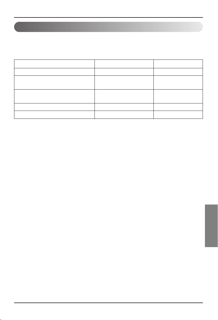
Externer Anschlussschaltplan
Montageanleitung 9
DEUTSCH
1. RS-485 communication line specification: 0.75mm
2
or above 2C shield, product to product: 200M,
total length: 1km
2. FT-10 communication line: Refer to the following table.
* Nod to node distance (max): 250m, maximum distance: 450m
* AWG: American Wire Gauge
Cable Type Line thickness (AWG) Diameter
TIA 568A Category 5 cable 24 0.5mm
Belden 88471 (PVC jacket) or 16 1.3mm
equivalent cable
Belden 85102(Tefzel jacket) or 16 1.3mm
equal cable
Level IV cable 22 0.65mm
JY(st)Y 2x2x0.8 20.4 0.8mm
Communication line specification
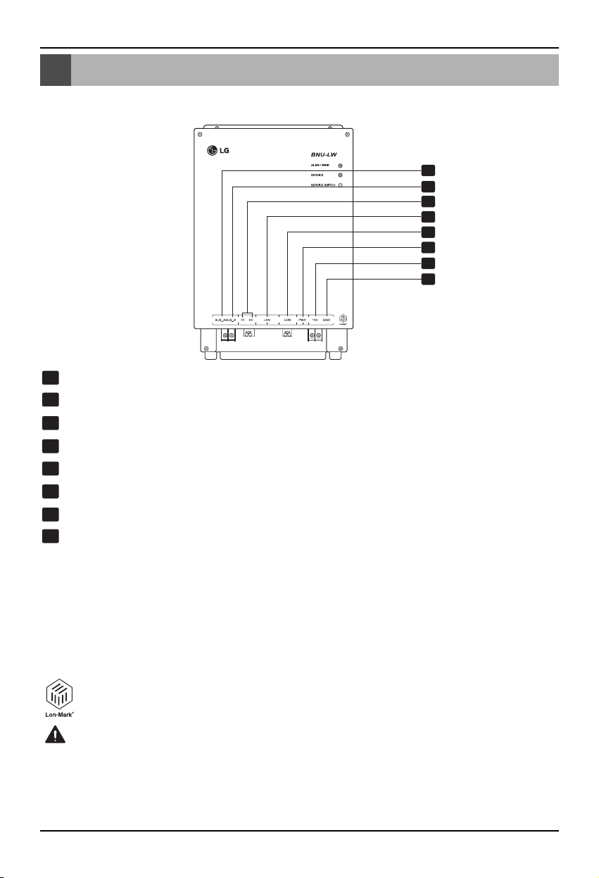
Bauteilbezeichnungen
10 Lonworks Gateway
Bauteilbezeichnungen
1
2
3
4
5
6
7
8
BUS_A: 485-Verbindungsleitung A (+)
BUS_B: 485-Verbindungsleitung B (-)
F1, F2: Anschlusskontakt Feuerwarnsystem (externes Gerät)
LAN: LAN-Anschluss für Web-Funktion
LON:
TP/FT-10-Verbindungsleitung (Verbindungsleitung Lonworks-System) ohne Polarität
PWR: Anschluss an 12V Gleichstrom-Netzadapter
12V: Anschluss ohne vorhandenen 12V Gleichstrom-Netzadapter
GND: Anschluss ohne vorhandenen GNS-Adapter
ALIVE/WINK: Blinkt im Normalbetrieb jede Sekunde
Blinkt fünf Mal bei Empfang eines WINK-Befehls des Lonworks-Systems
(Grün)
SERVICE: Leuchtet im Normalbetrieb nicht und blinkt ohne bestehende Verbindung
zum Lonworks-System. Leuchtet beim Drücken des Service-Schalters.
SERVICE SWITCH: Beim Drücken des Service-Schalters wird die Neuron-Kennung
zum Lonworks-System übertragen und die Service-LED leuchtet.
BNU-LW (PNF-B16A1) ist ein LON-MARK-zertifiziertes Produkt (Internationale
Norm). (Lon Mark Version 3.3)
1
8
2
3
4
5
6
7
LONWORKS GATEWAY
Die Anschlüsse Nr. 6 und Nr. 7, 8, sind für das Netzteil zuständig. Es darf daher nur einer
der beiden Anschlüsse verwendet werden. Verwenden Sie zur Gleichstromversorgung mit
DC12V Anschluss Nr. 6 (die Anschlüsse Nr. 7 und 8 müssen nicht genutzt werden.)
Verwenden Sie Anschlüsse Nr. 7 und 8, wenn die Stromversorgung NICHT mit DC12V-
Gleichstrom erfolgt (der Anschluss Nr. 6 muss nicht genutzt werden.)
ACHTUNG
Montagefolge
Montageanleitung 11
DEUTSCH
Montagefolge
1. Das Gerät muss je nach Einstellung der Zentralsteuerungsadresse des Innengerätes sowie des
DIP-Schalters des PI485-Gerätes installiert werden. (Schalten Sie den DIP-Schalter Nr. 4 auf EIN.)
(Einzelheiten finden Sie in der Montageanleitung des PI485-Gerätes.)
2. Verbinden Sie BUS_A und BUS_B (485-Verbindungsleitung). Achten Sie dabei auf die korrekte
Polarität. (Siehe nächste Seite.)
3.
LON (Anschluss TP/FT-10-Leitung Lonworks Gateway-Verbindungsleitung) TP/FT-10-
Verbindungsleitung besitzt keine Polarität. Schließen Sie zwei Verbindungsleitungen an die BMS an.
4. PWR (Netzteil)
Für das Netzteil kann einer der beiden ausgewählt werden.
Verwendung eines 12V Gleichstrom-Netzadapters
Schließen Sie Anschluss Nr. 6 unter Bauteilbezeichnungen an.
Ohne Adapter kann DC12 verwendet werden
Schließen Sie 12V und GND an die Anschlüsse Nr. 7 und Nr. 8 an.
5. Beim Drücken des Service-Schalters nach dem Anschluss des Lonworks-Systems leuchtet die
Service-LED auf und die Neuron-Kennung wird automatisch an das Lonworks-System übertragen.
6. Überprüfen Sie, ob die Service-LED nach zehn Minuten den Normalzustand erreicht hat (AUS).
Falls sich die Service-LED im Normalzustand befindet, wurde die Installation korrekt vorgenommen.
7. Bei Verwendung des Anschlusses für das Feuerwarnsystem, schließen Sie die beiden Anschlüsse
des Feuerwarnsensors an F1 und F2 an. (Der Feuerwarnsensor ist für einen Gleichstrom-Ausgang
von maximal 12V vorgesehen.)
8. Schließen Sie das LAN-Kabel nach der Installation zwischen den PCs an, um die korrekte
Installation des LG Produktes mit Hilfe des Web-Servers zu überprüfen. – Einzelheiten finden Sie
im Abschnitt Ferndiagnosefunktion (Seite 16).
Beim Anschluss der Signalleitung an den Anschluss des Lonworks Gateways muss ein
Treiber manuell installiert werden.
(Achten Sie darauf, die Anschlussleiste und die Leiterplatine nicht zu beschädigen.)
VORSICHT
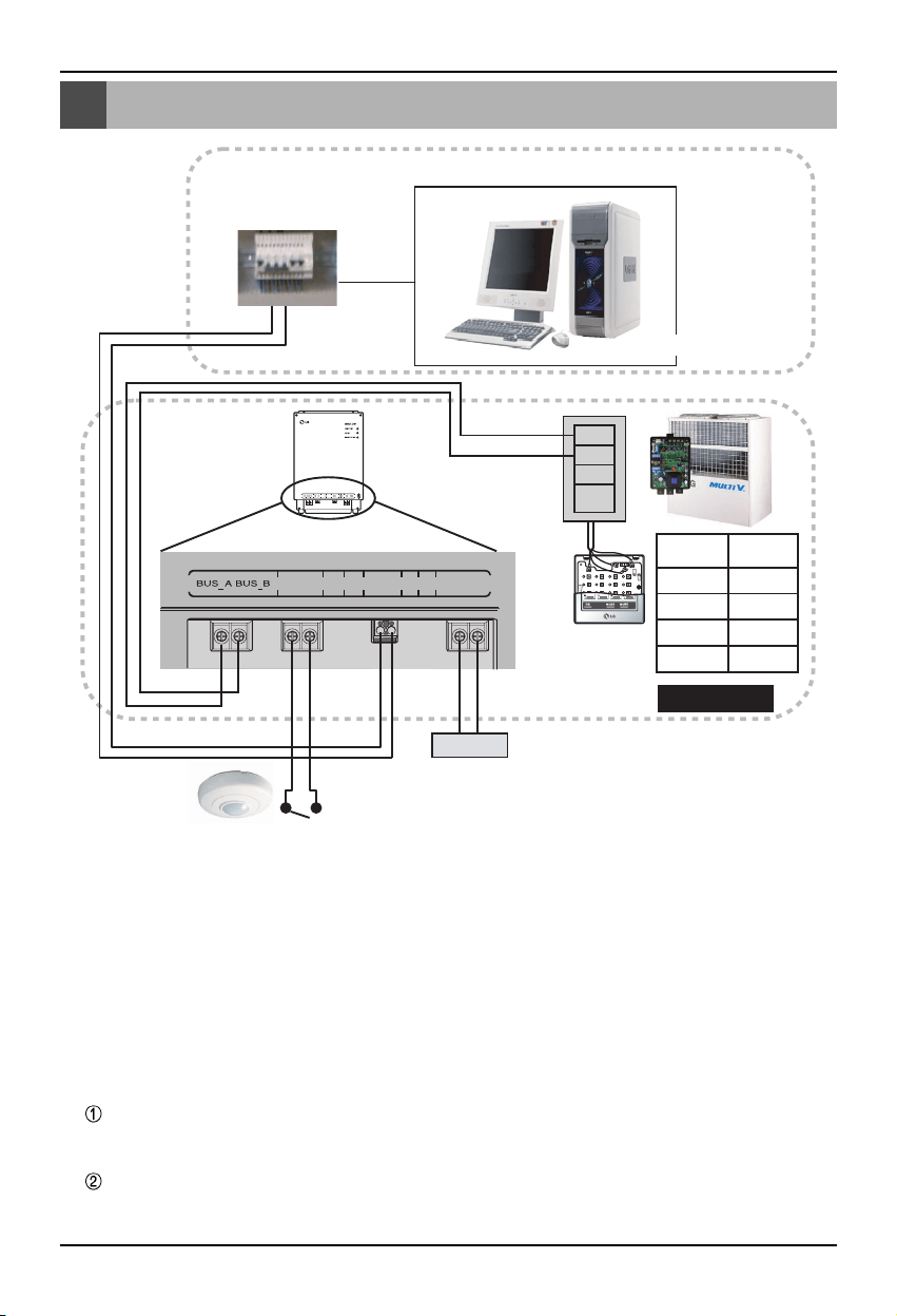
BNU-LW Anschlussfolge
12 Lonworks Gateway
BNU-LW Anschlussfolge
A
B
+10V
GND
TP/FT-10
LonWork
Adapter
Netz
BMS-Steuerung (PC)
Feuerwarnsensor
(Maximal 12V Gleichstrom)
F1 F2 LAN LON PWR 12V GND
PI485
Anschluss
Zentralst-
euerung
PI485
VOC
GND
C
D
10V
GND
BUS_A
BUS_B
LG stellt diesen Teil nicht bereit (Anschluss und Montage)
LG Geräte
[Anschlussfolge]
1. Schließen Sie die 485-Verbindungsleitung an
-
Achten Sie auf die korrekte Polarität an BUS A und
BUS B(Hinweise zum DIP-Schalter des 485-
Gateway erhalten Sie im Handbuch des Gateways.)
2. Schließen Sie die Lonworks-
Verbindungsleitung an (TP/FT-10)
- Keine Polarität.
3.
Netzteil (Wählen Sie Anschluss Nr. 1 oder Nr. 2)
Verwendung eines 12V Gleichstrom-Netzadapters
- Schließen Sie Anschluss Nr. 6 unter
Bauteilbezeichnungen an.
Stellen Sie eine 12V Gleichstromversorgung
des Montageortes her
- Schließen Sie 12V und GND an die
Anschlüsse Nr. 7 und Nr. 8 an.
4. Verbindung mit der einfachen
Zentralsteuerung
-
Stellen Sie DIP-Schalter Nr. 2 der einfachen
Zentralsteuerung auf EIN und nehmen Sie die
Einstellung gemäß der Adresse des Drehschalters vor.
(Genauere Hinweise zur Verbindung der einfachen
Zentralsteuerung finden Sie im Abschnitt Einstellungen
auf Seite 20.)
5. Verbindung des Feuerwarnsensors
- Wenn bei einem Feuer das Signal DC 12
oder darunter übertragen wird, werden das
mit dem BNU-LW verbundene Innengerät
sowie die Belüftung abgeschaltet.
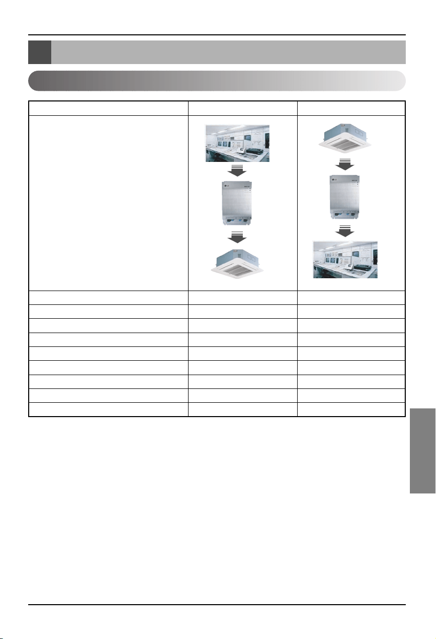
Funktionstabelle Klimagerät/Belüftung
Montageanleitung 13
DEUTSCH
Funktionstabelle Klimagerät/Belüftung
Innengerätefunktion
Einzelsteuerung InnengerätO O
Betriebsmoduswechsel O O
Änderung der Lüfterstärke O O
Temperatureinstellung O O
Sperre O O
Automatische Luftstromrichtung O O
Temperaturprüfung InnengerätX O
Fehlerprüfung X O
Gleichzeitiger Betrieb/Stop O X
Funktion
BMS
BNU-LW
Air conditioner
BMS
BNU-LW
Air conditioner
Klassifizierung Steuerung Überwachung
Verbindungsfunktion: Die Verbindungsfunktion bezieht sich auf den Fall, wenn der Ausgang eines
Gerätes vom Eingang eines anderen Gerätes abhängig ist und eine Änderung
des Eingangs eine Änderung des Ausgangs zur Folge hat. Die
Verbindungsfunktion arbeitet auch mit Lon-Gerätes anderer Hersteller
zusammen.
Beispiel: Wenn der EIN/AUS-Ausgang von Innengerät Nr. 1 vom EIN/AUS-Eingang von Innengerät
Nr. 2 abhängig ist und Innengerät Nr. 1 eingeschaltet wird, empfängt Innengerät Nr. 2
dieses Signal und wird ebenfalls eingeschaltet.

Funktionstabelle Klimagerät/Belüftung
14 Lonworks Gateway
Belüftungsfunktion Innengerät
Einzelsteuerung InnengerätO O
Betriebsmoduswechsel O O
Änderung der Lüfterstärke O O
Benutzer-Betriebsmodus
OO
(Schnellbelüftung, Stromsparbetrieb, Erwärmung)
Sperre O O
Fehlerprüfung X O
Gleichzeitiger Betrieb/Stop O X
Funktion
BMS
BNU-LW
Ventilation
BMS
BNU-LW
Ventilation
Klassifizierung Steuerung Überwachung
Verbindungsfunktion: Die Verbindungsfunktion bezieht sich auf den Fall, wenn der Ausgang eines
Gerätes vom Eingang eines anderen Gerätes abhängig ist und eine Änderung
des Eingangs eine Änderung des Ausgangs zur Folge hat. Die
Verbindungsfunktion arbeitet auch mit Lon-Gerätes anderer Hersteller
zusammen.
Beispiel: Wenn der EIN/AUS-Ausgang von Innengerät Nr. 1 vom EIN/AUS-Eingang von Innengerät
Nr. 2 abhängig ist und Innengerät Nr. 1 eingeschaltet wird, empfängt Innengerät Nr. 2
dieses Signal und wird ebenfalls eingeschaltet.
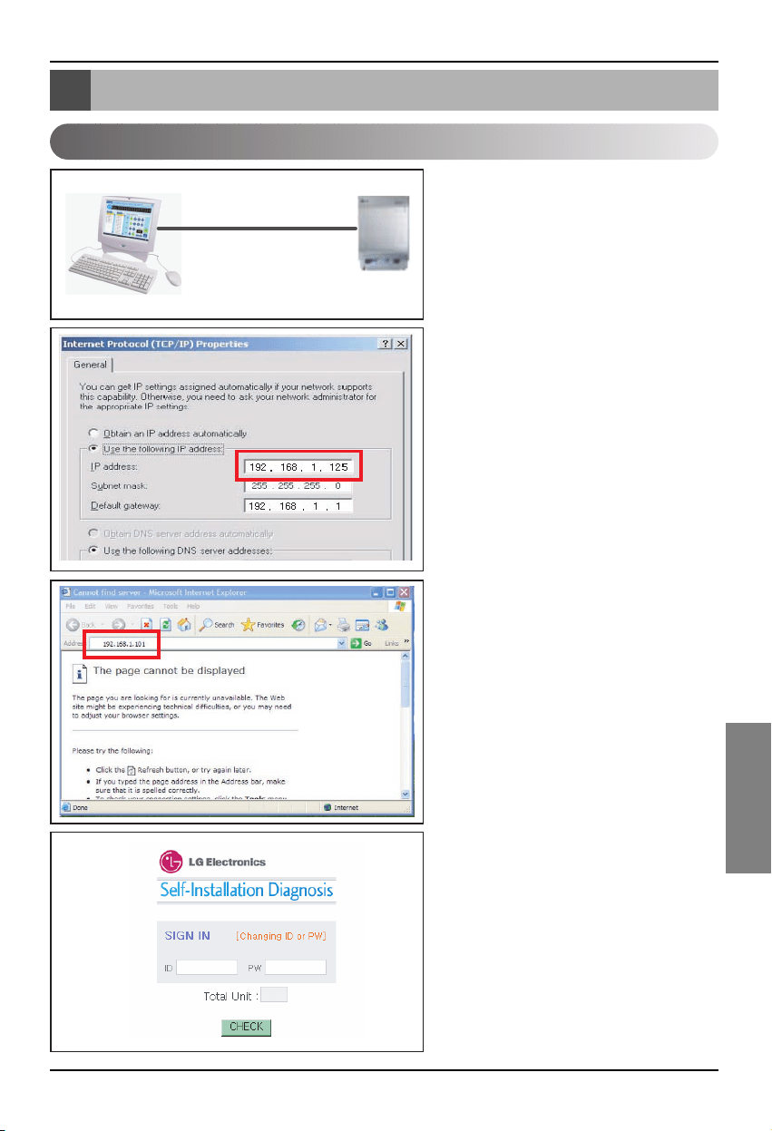
Ferndiagnosefunktion des BNU-LW
Montageanleitung 15
DEUTSCH
1.
Verbinden Sie den PC über ein LAN-
Kabel am LAN-Anschluss des BNU-LW.
2.
Stellen Sie die Netzwerk-IP des PCs auf
192.168.1.xxx (mit Ausnahme von 101) ein.
3. Geben Sie im Internet Explorer die IP-
Adresse 192.168.1.101 ein.
4. Bei korrekter Verbindung wird das hier
gezeigte Bild angezeigt.
• Werkseitige Kennung: lonwork
• Werkseitiges Kennwort: lonwork
•
Geben Sie im Abschnitt Gesamtanzahl
Geräte die Gesamtanzahl der
angeschlossenen Innengeräte ein.
Ferndiagnosefunktion des BNU-LW
Einstellungsmöglichkeiten
LAN(cross cable)

Ferndiagnosefunktion des BNU-LW
16 Lonworks Gateway
Konfiguration
•
Nach der Eingabe des
Mitgliedsnamen und des Kennworts
wird an den derzeit angeschlossenen
Klima- und Belüftungsgeräten
Folgendes angezeigt.
• m Abschnitt “A” wird die Anzahl der
derzeit angeschlossenen Klima-
und Belüftungsgeräte angezeigt.
•
Steuerung eines der Geräte ➀ Wählen
Sie das Gerät aus – ➁ Stellen Sie die
Adresse ein – ➂ Geben Sie den Befehl
EIN/AUS – ➃ Wählen Sie den
Betriebsmodus – ➄ Klicken Sie auf
Überprüfen, um das Gerät zu steuern.
•
Um den aktuellen Status der Gerätes
➅
abzurufen, klicken auf
Aktualisieren. In Abschnitt “B” wird
nun der aktuelle Status des
Innengerätes angezeigt.
•
Um die aktuelle IP-Adresse zu
ändern, klicken Sie auf [Netzwerkort
festlegen].
"A"
"B"
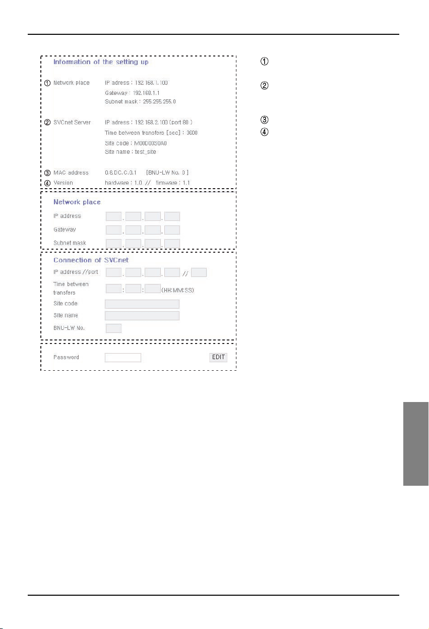
Ferndiagnosefunktion des BNU-LW
Montageanleitung 17
DEUTSCH
A
B
C
D
A:
Anzeige der aktuellen IP-Adresse, des
Gateways und der Subnetzmaske.
Um den SVCnet-Server zu nutzen,
lesen Sie die Informationen zum
SVCnet-Server.
Anzeige der MAC-Adresse.
Anzeige der aktuellen
Versionsinformationen des BNU-LW.
B: Klicken Sie zum Ändern der IP-
Adresse, des Gateways und der
Subnetzmaske auf die Schaltfläche
Bearbeiten direkt neben den zu
ändernden Informationen.
C:
Feld zur Eingabe der SVCnet-Serverdaten
zur Verbindungsherstellung.
SVCnet-Server ist ein Dienst, mit dessen
Hilfe über den LG Electronics-
Kundendienst künftig der Status eines
Klimagerätes abgefragt werden kann, das
über ein LAN mit dem BNU-LW verbunden
ist, um Störungen rechtzeitig zu melden.
D: Um Änderungen am Netzwerk oder
sonstige Änderungen zu verhindern,
wurde eine Sicherheitsfunktion mit
einem werkseitig eingestellten
Anmelde-Kennwort integriert.
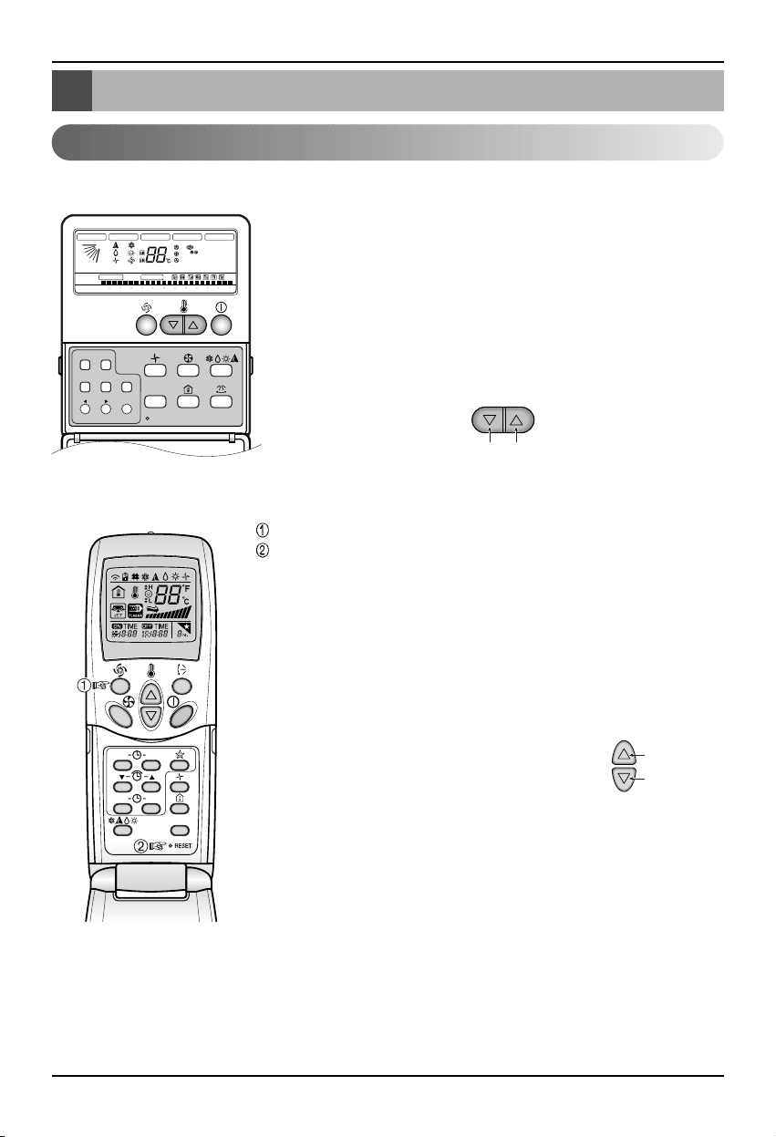
Einstellung der Innengeräte-Adresse
18 Lonworks Gateway
Einstellung der Innengeräte-Adresse
Einstellung der Innengeräte-Adresse
Verwendung der Kabel-Fernbedienung
Verwendung der schnurlosen Fernbedienung
Timer Cancel
Program Week
Hour Min
Holiday
Set/Clr
RESET
ZONE
1234
Operation unit
Humidify
JET
AUTO
AUTO SWING OPERATION
FAN SPEED
Program set
SUB FUNCTION
SET TEMP
Room Temp
HI
MED
LO
Heater
Defrost
Filter
Preheat
Out door
Time
Timer
On
Set no. Time
Off
01 03 05 07 09 11 13 15 17 19 21 23
Plasma
ON OFF
SET
CANCEL
PLASMA
Gruppennr. Innengerätenr.
Temperatureinstellung
1. Halten Sie die Tasten Wochentag und Zeitschaltuhr
einstellen/abbrechen gleichzeitig drei Sekunden lang gedrückt.
2. Stellen Sie über die Taste zur Temperatureinstellung die
Innengeräte-Adresse ein.
Einstellbereich: 00-FF
3. Halten Sie die Tasten Wochentag und Zeitschaltuhr
einstellen/abbrechen gleichzeitig drei Sekunden lang gedrückt,
um die Einstellung der Adresse zu beenden.
Einstellmodus Adresse
1. Halten Sie die obere, linke Taste mindestens drei Sekunden lang gedrückt.
Halten Sie diese Taste gedrückt und betätigen Sie dann die Reset-Taste.
❈ Je nach Modell sind die kabellosen Fernbedienungen unterschiedlich
gearbeitet.
2.
Stellen Sie über die Taste zur Temperatureinstellung die Innengeräte-Adresse ein.
Einstellbereich: 00-FF
3. Drücken Sie nach der Einstellung der Adresse den EIN-/AUS-Schalter einmal in
Richtung Innengerät.
4. Das Innengerät zeigt daraufhin die eingestellte Adresse ein und die Einstellung
ist somit beendet. (Dauer und Art der Adressenanzeige
können je nach Innengerätetyp variieren.)
5. Setzen Sie die Fernbedienung zurück, um den allgemeinen
Betriebsmodus einzustellen.
Überprüfung der Adresse
1.
Halten Sie die obere, rechte Taste gedrückt und betätigen Sie die Reset-
Taste.(Halten Sie die linke Taste mindestens drei Sekunden lang gedrückt.)
2.
Drücken Sie den EIN-/AUS-Schalter einmal in Richtung Innengerät, so dass
die eingestellte Adresse im Anzeigefenster des jeweiligen Innengerätes
erscheint.(Dauer und Art der Adressenanzeige können je nach
Innengerätetyp variieren.)
3. Setzen Sie die Fernbedienung zurück, um den allgemeinen Betriebsmodus
einzustellen.
❈ Je nach Herstellungsdatum einiger Kabel- bzw. schnurlosen Fernbedienungen ist die oben
beschriebene Funktion u. U. nicht möglich.
Dies hat keinen Einfluss auf die Bedienung, da die Adresse mit Hilfe einer Fernbedienung mit einer
solchen Einstellungsfunktion während der Installation eingestellt werden kann.
Gruppennr.
Innengerätenr.
Temperatureinstellung
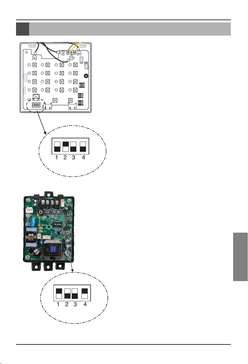
Verbindung mit der einfachen Zentralsteuerung
Montageanleitung 19
DEUTSCH
Verbindung mit der einfachen Zentralsteuerung
Verbindung mit der einfachen
Zentralsteuerung
• Stellen Sie zur Verbindung mit der einfachen
Zentralsteuerung den DIP-Schalter Nr. 2 der einfachen
Zentralsteuerung auf EIN.
• Stellen Sie den Drehschalter auf die Gruppenadresse des zu
steuernden Innengerätes ein.
Einstellung des PI-485
Einstellung des PI-485
• Das BNU-LW nutzt das LGAP-Verbindungsprotokoll.
DIP-Schalter Nr. 1 und Nr. 4 des PI-485 können auf EIN
eingestellt werden.
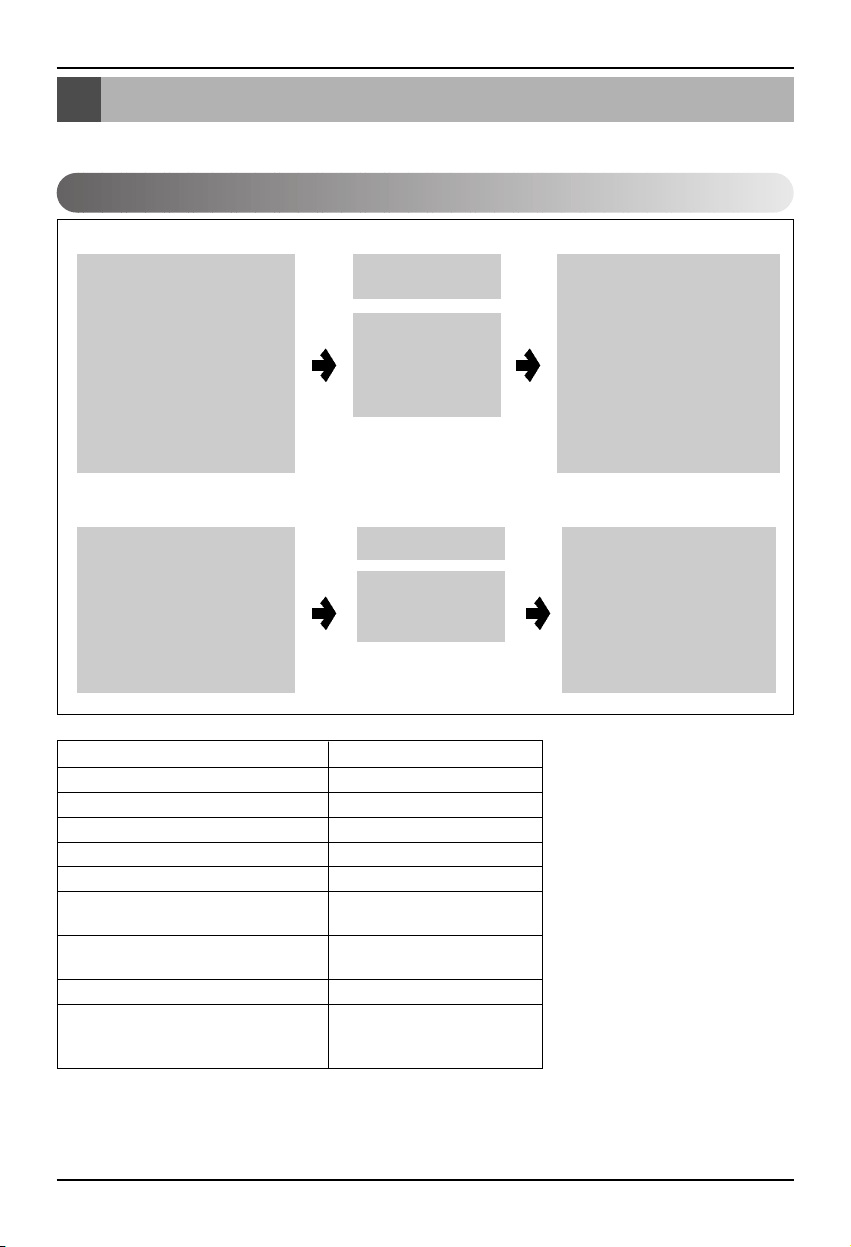
Anhang
20 Lonworks Gateway
Anhang
Klimageräteobjekte
• Die Informationen in diesem Anhang sind nur zur BMS-Verbindung und nicht zur tatsächlichen
Installation erforderlich.
Standardfunktionen
SCC(8500)FB
Netzwerkvariablen
Innengerät/Belüftu
ngsgerät
SNVT
_
switch nviOnOff
SNVT
_
hvac
_
mode nviHeatCool
SNVT
_
switch nviFanSpeedcmd
SNVT
_
switch nviLock
SNVT
_
switch nviSwing
SNVT
_
switch nviSetPoint
SNVT
_
switch nviUser
SNVT
_
switch nviSpaceTemp
SNVT
_
switch nvoOnOff
SNVT
_
hvac
_
mode nvoHeatCool
SNVT
_
switch nvoFanSpeed
SNVT
_
switch nvoLock
SNVT
_
switch nvoSwing
SNVT
_
temp
_
P nvoSetPoint
SNVT
_
hvac
_
status nvoUnitStatus
SNVT
_
count nvoUser
SWITCH(3200)F
Gesamtsteuer
ung
SNVT
_
switch
nviTotalOnOff
_
Indoor
SNVT
_
switch
nviTotalOnOff
_
Vent
SNVT
_
switch nvoSwitch
•
Steuerung und Überwachung kann, wie in der Abbildung gezeigt, für ein Klima-/Belüftungsgerät
aktiviert werden.
• Die Netzwerkvariable kann sich von der tatsächlichen Netzwerkvariable unterscheiden.(Hinweise zur
korrekten Netzwerkvariablen finden Sie in der XIF-Datei.)
Steuerung Überwachung
Befehl Ein/Aus
Befehl Betriebsmodus
Befehl Auswahl Lüfterstärke
Befehl Innengerät sperren
Befehl Luftstromrichtung
Befehl Temperatureinstellung
Befehl Zusätzliche Belüftungsfunktionen
(Nur für Belüftungsgeräte)
Befehl Alle Klimageräte Ein/Aus
Befehl Alle Belüftungsgeräte Ein/Aus
Überwachung Status Ein/Aus
Überwachung Betriebsart
Überwachung Lüfterstärke
Überwachung Sperre
Überwachung Luftstromrichtung
Überwachung
Temperatureinstellung
Überwachung Aktuelle
Temperatur
Fehleranzeige
Überwachung Zusätzliche
Belüftungsfunktionen(Nur für
Belüftungsgeräte)
Anhang
Montageanleitung 21
DEUTSCH
Air conditioner control/monitoring point
1 EIN/AUS (Einstellung) SNVT_switch nviOnOff_nn Eingang Stop
Betrieb
2 EIN/AUS (Status) SNVT_switch nvoOnOff_nn Ausgang Stop
Betrieb
3 Sperre (Einstellung) SNVT_switch nviLock_nn Eingang
Abbrechen Einstellung
4 Sperre (Status) SNVT_switch nvoLock_nn Ausgang
Abbrechen Einstellung
5 Betriebmodus (Einstellung) SNVT_hvac_modenviHeatCool_nn Eingang Auto
Erwärmung
Kühlung Lüfter
Entfeuchtung
6 Betriebsmodus (Status) SNVT_hvac_mode nviHeatCool_nn Ausgang Auto
Erwärmung
Kühlung Lüfter
Entfeuchtung
7 Schwingen (Einstellung) SNVT_switch nviSwing_nn Eingang
Abbrechen Einstellung
8 Schwingen (Status) SNVT_switch nvoSwing_nn Ausgang
Abbrechen Einstellung
9
Lüftergeschwindigkeit (Einstellung)
SNVT_switch nviFanSpeedCmd_nn Eingang Niedrig Mittel Hoch Auto
Schwach
10
Lüftergeschwindigkeit (Status)
SNVT_switch nvoFanSpeed_nn Ausgang Niedrig Mittel Hoch Auto
Schwach
11
Eingestellte Raumtemperatur
SNVT_temp_p nviSetPointCmd_nn Eingang °C
12
Eingestellte Raumtemperatur
SNVT_temp_p nvoSetPoint_nn Ausgang °C
13 Raumtemperatur SNVT_temp_p nvoSpaceTemp_nn Ausgang °C
14 Fehlercode SNVT_hvac_status nvoUnitStatus_nn Ausgang
Kein Fehler Hinweise finden Sie in den Fehlercodes zum LG Klimagerät.
Kompo
nente.
Nr.
Name
Objekttyp
Gerät
code 0 code 1 code 2 code 3 code 4 code 5 code 9 code 14
Objektname
(nn: Klimagerät und
Lüftergruppe/Innengeräte-Adresse)

Anhang
22 Lonworks Gateway
Ventilation control/monitoring point
1 EIN/AUS (Einstellung) SNVT_switch nviOnOff_nn Eingang Stop Betrieb
2 EIN/AUS (Status) SNVT_switch nvoOnOff_nn Ausgang Stop Betrieb
3 Sperre (Einstellung) SNVT_switch nviLock_nn Eingang
Abbrechen
Einstellung
4 Sperre (Status) SNVT_switch nvoLock_nn Ausgang
Abbrechen
Einstellung
5 Betriebmodus (Einstellung) SNVT_hvac_modenviHeatCool_nn Eingang Auto
Erwärmung
Normal
6 Betriebsmodus (Status) SNVT_hvac_mode nviHeatCool_nn Ausgang Auto
Erwärmung
Normal
7 SNVT_switch nviFanSpeedCmd_nn Eingang Niedrig Hoch
Sehr hoch
8 SNVT_switch nvoFanSpeed_nn Ausgang Niedrig Hoch
Sehr hoch
9 Fehlercode SNVT_hvac_status nvoUnitStatus_nn Ausgang Hinweise finden Sie in den Fehlercodes zum LG Klimagerät.
10
Benutzermodus (Einstellung)
SNVT_count nviUser_nn Ausgang Schnell Wärme
11 Benutzermodus (Status) SNVT_count nvoUser_nn Ausgang Schnell Wärme
Kompo
nente.
Nr.
Name
Objekttyp
Gerät
code 0 code 1 code 2 code 3 code 5 code 9
Objektname
(nn: Klimagerät und
Lüftergruppe/Innengeräte-Adresse)
Lüftergeschwindigkeit
(Einstellung)
Lüftergeschwindigkeit
(Status)
Stromspa-
rbetrieb
Stromspa-
rbetrieb
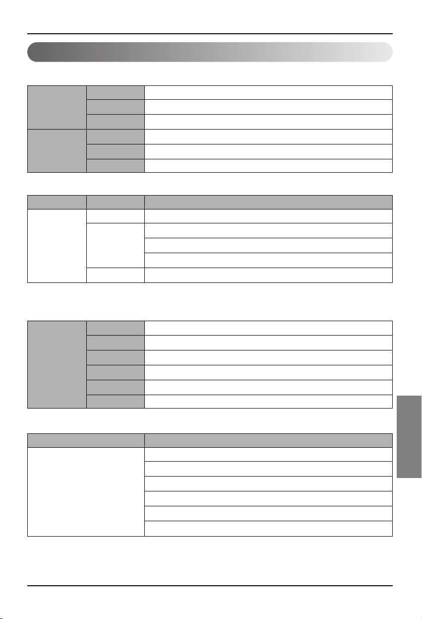
Anhang
Montageanleitung 23
DEUTSCH
Netzwerkvariablen
1) Einzelbetrieb/Einzelstop Eingang/Ausgang (Klimagerät/Belüftung)
Gültiger Bereich
SNVT_switch
( Index : 95 )
NV Feld Betrieb
Funktion Eingang Betrieb/Stop
Eingang Verwendete NV Netzwerk-Eingangsvariable : SNVT_switch nviOnOff_n
Betrieb Steuert den Betrieb/Stop jedes Gerätes (Klimagerät/Belüftung)
Funktion Statusanzeige Betrieb/Stop
Ausgang Verwendete NV Netzwerk-Ausgangsvariable : SNVT_switch nvoOnOff_n
Betrieb Überwacht den Betriebsstatus jedes Gerätes (Klimagerät/Belüftung)
2) Betriebsmodus Eingang/Ausgang (Klimagerät/Belüftung)
Funktion Befehlseingabe Betriebsmodus
Eingang Verwendete NV Netzwerk-Eingangsvariable : SNVT_hvac_mode nviHeatCool_n
Betrieb Steuert den Betriebsmodus jedes Klima-/Belüftungsgerätes.
Funktion Statusanzeige Betriebsmodus
Ausgang Verwendete NV Netzwerk-Ausgangsvariable : SNVT_hvac_mode nvoHeatCool_n
Betrieb Überwacht den Betriebsstatus jedes Klima-/Belüftungsgerätes.
value Nicht belegt (normalerweise 0%)
0 = Klimagerät/Belüftung AUS
Zustand 1 = Klimagerät/Belüftung EIN
Standardwert
HVAC_AUTO:0 = Automatik-Betrieb (Auto), Automatik-Belüftung
HVAC_HEAT:1 = Heizbetrieb (Wärme), Wärmebelüftung
HVAC_COOL: 3 = Kühlungsbetrieb (Kälte)
HVAC_FAN_ONLY:9 = Lüfterbetrieb (Lüfter), normale Belüftung
HVAC_DEHUMID:14 = Trocknungsbetrieb (Entfeuchtung)
Standardwert
Gültiger Bereich
SNVT_hvac_mode
(Index: 108)
NV Betrieb
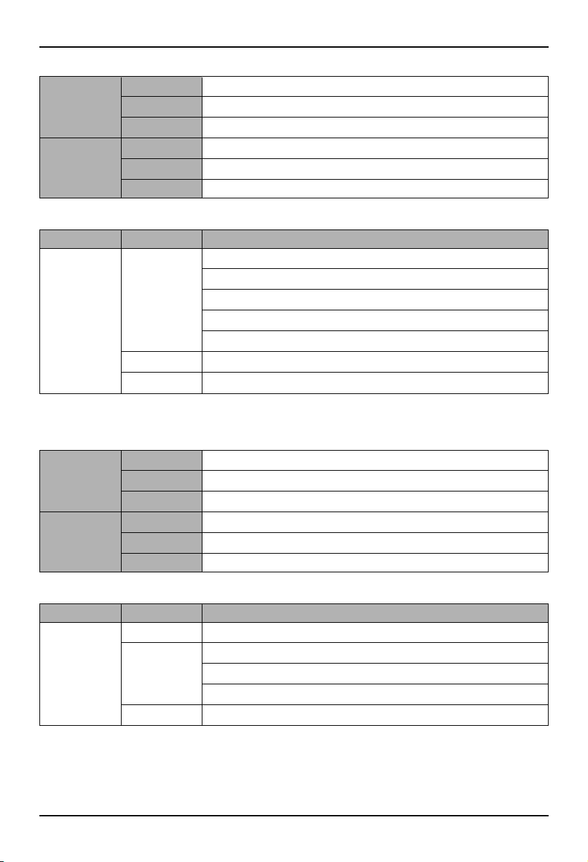
Anhang
24 Lonworks Gateway
1: Lüfter Klimagerät niedrig, Lüfter Belüftung niedrig
2: Lüfter Klimagerät mittel, Lüfter Belüftung hoch
Wert 3: Lüfter Klimagerät hoch, Lüfter Belüftung sehr hoch
4: Lüfter Klimagerät autom., Lüfter Belüftung autom.
5. Lüfter Klimagerät sehr niedrig
Zustand 0: Gerät nicht aktiv, 1: Gerät aktiv
Standardwert
3) Lüfterstärke Eingangs-/Ausgangsbefehl (Klimagerät/Belüftung)
Gültiger Bereich
SNVT_switch
( Index : 95 )
NV Feld Betrieb
Funktion Eingangsbefehl Lüfterstärke
Eingang Verwendete NV Netzwerk-Eingangsvariable : SNVT_switc nviFanSpeedCmd_n
Betrieb Steuert die Lüfterstärke jedes Innengerätes.
Funktion Statusanzeige Lüfterstärke
Ausgang Verwendete NV Netzwerk-Ausgangsvariable : SNVT_switch nvoFanSpeed_n
Betrieb Überwacht die Lüfterstärke jedes Gerätes (Klimagerät/Belüftung)
Wert Nicht belegt (normalerweise 0%)
0 = Sperre Klimagerät/Belüftung AUS
Zustand 1 = Sperre Klimagerät/Belüftung EIN
Standardwert
4) Sperre Eingang/Ausgang (Klimagerät/Belüftung)
Gültiger Bereich
SNVT_switch
( Index : 95 )
NV Feld Betrieb
Funktion Befehlseingabe Einstellung Sperre
Eingang Verwendete NV Netzwerk-Eingangsvariable : SNVT_switch nviLock_n
Betrieb Steuert die Sperre jedes Gerätes (Klimagerät/Belüftung)
Funktion Statusanzeige Sperre
Ausgang Verwendete NV Netzwerk-Ausgangsvariable : SNVT_switch nvoLock_n
Betrieb Überwacht den Sperrstatus jedes Gerätes (Klimagerät/Belüftung)
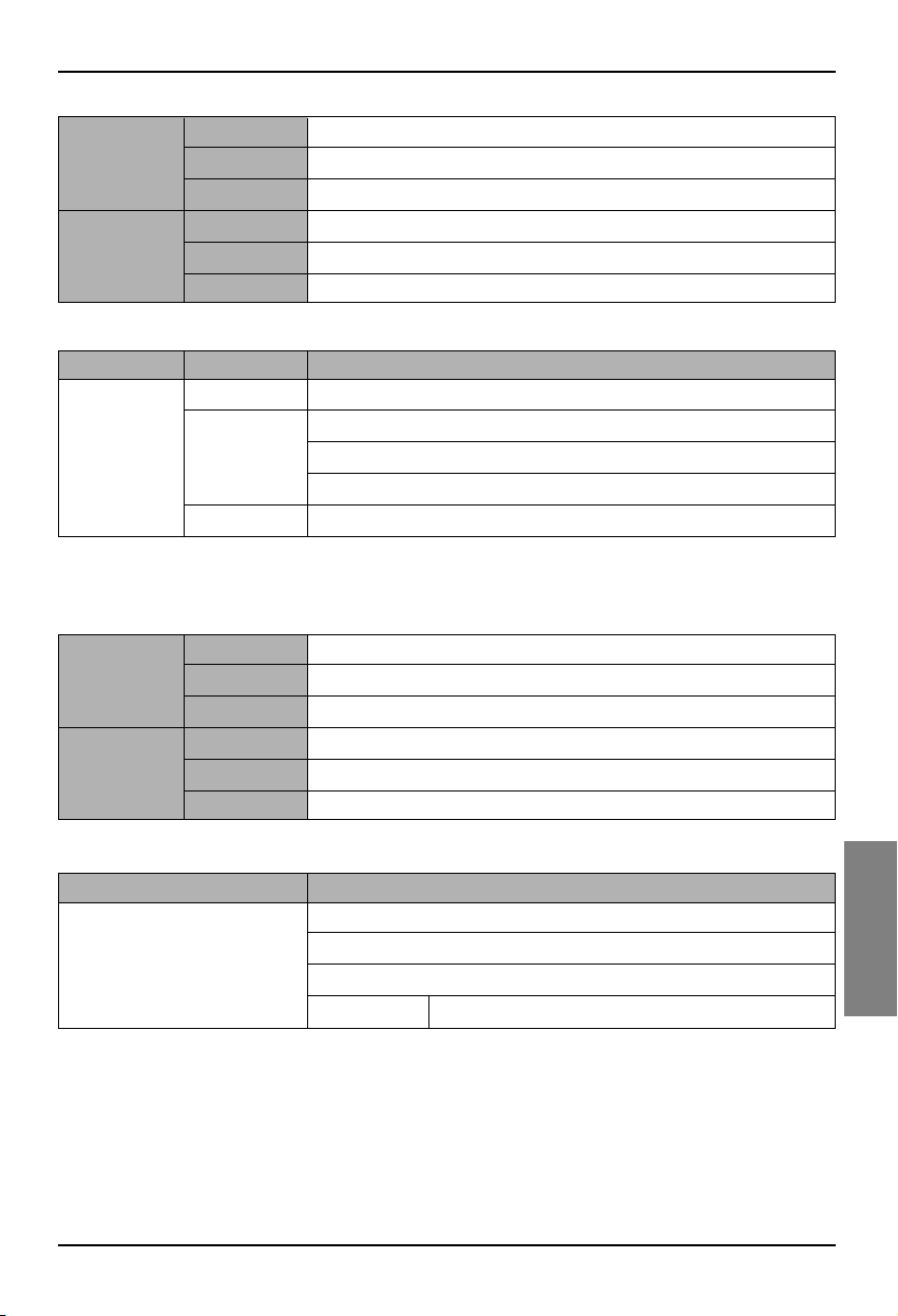
Anhang
Montageanleitung 25
DEUTSCH
Wert Nicht belegt (normalerweise 0%)
0 = Feste Luftstromrichtung für Klimagerät
Zustand 1 = Autom. Luftstromrichtung für Klimagerät
Standardwert
5) Autom. Luftstromrichtung Eingang/Ausgang (Nur für Klimagerät)
Gültiger Bereich
SNVT_switch
( Index : 95 )
NV Feld Betrieb
Funktion Befehlseingabe Autom. Luftstromrichtung
Eingang Verwendete NV Netzwerk-Eingangsvariable : SNVT_switch nviSwing_n
Betrieb Steuert die Luftstromrichtung jedes Gerätes (Klimagerät/Belüftung)
Funktion Statusanzeige Autom. Luftstromrichtung
Ausgang Verwendete NV Netzwerk-Ausgangsvariable : SNVT_switch nvoSwing_n
Betrieb Überwacht die Luftstromrichtung jedes Gerätes (Klimagerät/Belüftung)
6) Temperatureinstellung Eingang/Ausgang (Nur für Klimagerät)
Funktion Eingang eingestellter Temperaturbereich
Eingang Verwendete NV Netzwerk-Eingangsvariable : SNVT_switch nviSetPoint_n
Betrieb Steuert die Temperatureinstellung jedes Gerätes (Klimagerät/Belüftung)
Funktion Statusanzeige eingestellter Temperaturbereich
Ausgang Verwendete NV Netzwerk-Ausgangsvariable : SNVT_switch nvoSetPoint_n
Betrieb Überwacht die eingestellte Temperatur jedes Gerätes (Klimagerät/Belüftung)
Im Kühlungsbetrieb: -10 bis 40°C
Im Heizbetrieb: -18 bis 30°C
Im Trocknungsbetrieb und Lüfterbetrieb: Nicht verfügbar
Standardwert
Gültiger Bereich
SNVT_switch
( Index : 95 )
NV Betrieb

Anhang
26 Lonworks Gateway
7) Statusanzeige Innentemperatur (Nur für Klimagerät)
Funktion Statusanzeige Innentemperatur
Ausgang Verwendete NV Netzwerk-Ausgangsvariable : SNVT_switch nvoSpaceTemp_n
Betrieb Überwacht die Innentemperatur.
8) Fehlerausgabe (Klimagerät/Belüftung)
Funktion Anzeige Fehlerstatus
Ausgang Verwendete NV Netzwerk-Eingangsvariable : SNVT_hvac_Status nvoUnitStatus_n
Betrieb Überwacht den Fehlerstatus jedes Gerätes (Klimagerät/Belüftung)
Im Kühlungsbetrieb: 10 bis 40°C
Im Heizbetrieb: 10 bis 40°C
Im Trocknungsbetrieb und Lüfterbetrieb: Nicht verfügbar
Standardwert
Gültiger Bereich
SNVT_switch
( Index : 95 )
NV Betrieb
Modus Anzeige aktuelle Betriebsart
Heat_output_primary Nicht belegt
Heat_output_Secondary Nicht belegt
Cool_output Nicht belegt
Cool_output Nicht belegt
Econ_output Nicht belegt
fan_output Nicht belegt
In_alarm Anzeige Fehlercode
Gültiger Bereich
SNVT_switch
( Index : 112 )
NV Feld Betrieb
* Die Fehlercodes finden Sie in der Tabelle der Fehlercodes im Handbuch des Gerätes.
Anhang
Montageanleitung 27
DEUTSCH
10) Alle Innengeräte der Klimaanlage starten/anhalten
Funktion Befehlseingabe Alle anhalten
Eingang Verwendete NV Netzwerk-Eingangsvariable : SNVT_switch nviTotalONOFF_indoor
Betrieb Schaltet alle Belüftungseinheiten EIN bzw. AUS.
11) Alle Belüftungs-Innengerät starten/anhalten
Funktion Befehlseingabe Alle anhalten
Eingang Verwendete NV Netzwerk-Eingangsvariable : SNVT_switch nviTotalONOFF_indoor
Betrieb Schaltet alle Belüftungseinheiten EIN bzw. AUS.
0 = Nicht belegt
Wert
1 = Schnell
2 = Stromsparbetrieb
3 = Wärme
9) Befehl Belüftungsfunktion (Nur für Belüftungsgerät)
Gültiger Bereich
SNVT_count
( Index : 8 )
NV Feld Betrieb
Funktion Eingabe Benutzerdefinierte Betriebsart der Belüftung
Eingang Verwendete NV Netzwerk-Eingangsvariable : SNVT_count nviUser_n
Betrieb Steuert die Gerätefunktion jedes Belüftungsgerätes.
Funktion Status Benutzerdefinierte Betriebsart der Belüftung
Ausgang Verwendete NV Netzwerk-Ausgangsvariable : SNVT_count nvoUser_n
Betrieb Überwacht den Funktionsstatus jedes Belüftungsgerätes.
Wert Nicht belegt
Zustand
1 = Alle Innengeräte/Belüftungsgeräte EIN
0 = Alle Innengeräte/Belüftungsgeräte AUS
Standardwert
Gültiger Bereich
SNVT_switch
( Index : 95 )
NV Feld Betrieb

Mitteilung
28 Lonworks Gateway

P/No.: 3828A20494S
After reading this manual, keep it in a place easily accessible to the user for future reference.
Printed in Korea
CHINESE
LG
BNU-LW(Lonworks 网关)
安装手册

2
Lonworks 网关
BNU-LW (Lonworks 网关)
内 容
安全注意事项 .............................................................................................................3
总体系统图 ................................................................................................................7
外部接线图 ................................................................................................................8
如何设置连接到BNU-LW(Lonworks 网关)室内机的中央控制器的地址 ................
8
通讯线路规格 .......................................................................................................
9
各部件名称 ..............................................................................................................10
安装顺序 ..................................................................................................................11
BNU-LW 接线顺序 .................................................................................................12
空调/通风功能表 .....................................................................................................13
空调室内机功能 ..................................................................................................
13
通风室内机功能 ..................................................................................................
14
BNU-LW 远程诊断功能 ..........................................................................................15
设置方法 .............................................................................................................
15
配置 ....................................................................................................................
16
设置室内机的地址 ...................................................................................................18
设置室内机的地址 ..............................................................................................
18
连接到简单中央控制器 ............................................................................................19
附录 .........................................................................................................................20
A/C 对象 ............................................................................................................
20
空调控制/监视点 ................................................................................................
21
通风控制/监视点 ................................................................................................
22
网络变量 .............................................................................................................
23
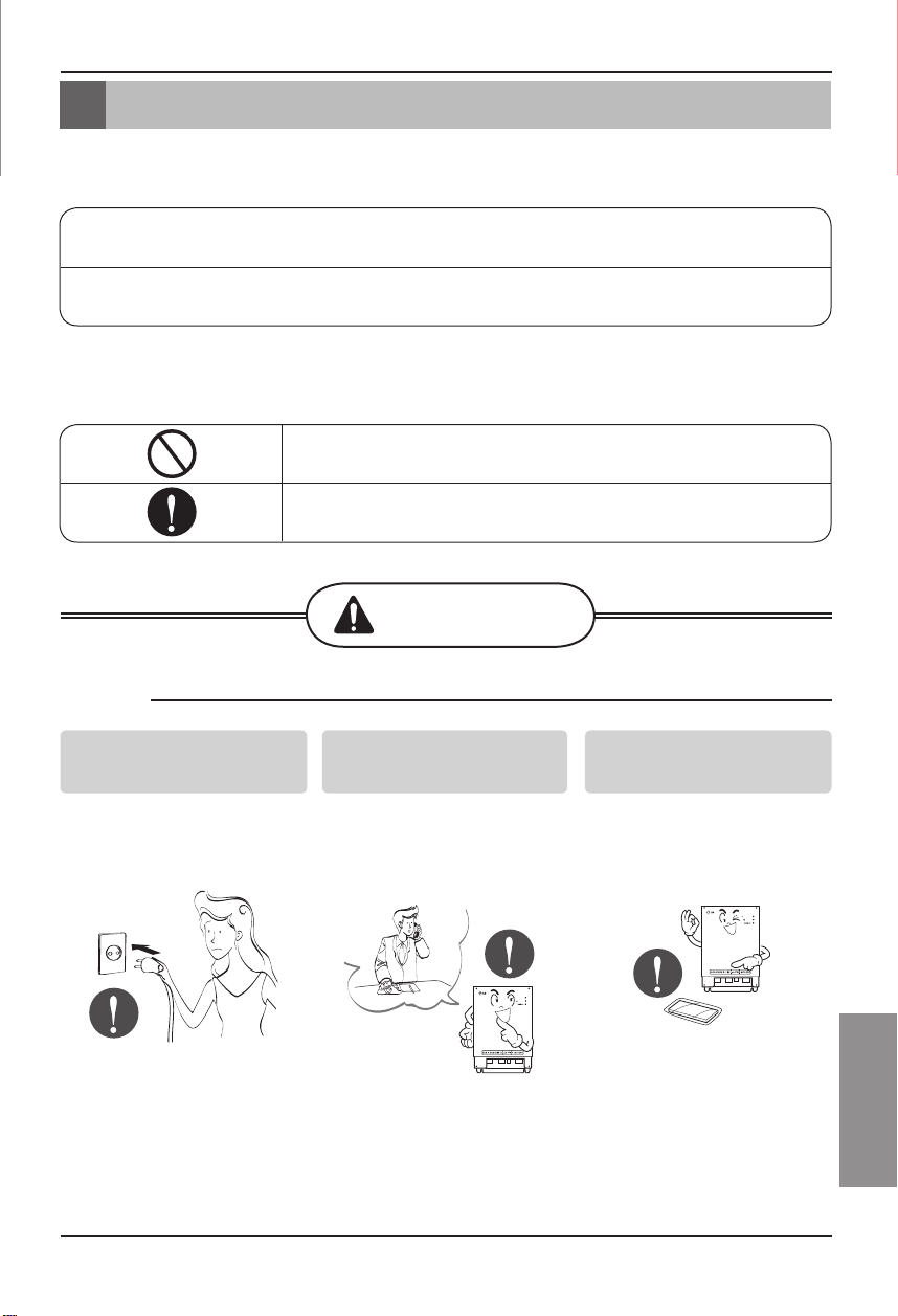
安装手册
3
CHINESE
安全注意事项
请不要通过插上或拔下电源
插头来使用或关闭此产品。
• 否则会导致电击或由于发热
而引起火灾。
咨询服务中心或设施专营店
获取产品设备。
• 否则会导致事故、电击、爆
炸或造成人身伤害。
使用标准零件。
• 使用非标准零件会导致电
击、爆炸、故障或造成人身
伤害。
■ 操 作
BNU-LW
BNU-LW
安全注意事项
为了避免对用户和他人带来人身伤害和财产损失,必须遵守以下注意事项。
■ 不遵守操作指南的错误操作会导致人身伤害和财产损失。严重程度通过以下两种方式来表示。
■ 此手册中使用的符号含义说明如下。
此符号表示可能造成死亡或严重伤害。
此符号表示可能造成损伤或伤害。
请不要执行此操作。
请按照说明操作。
BNU-LW (Lonworks 网关)
内 容
警 告
小 心
警 告
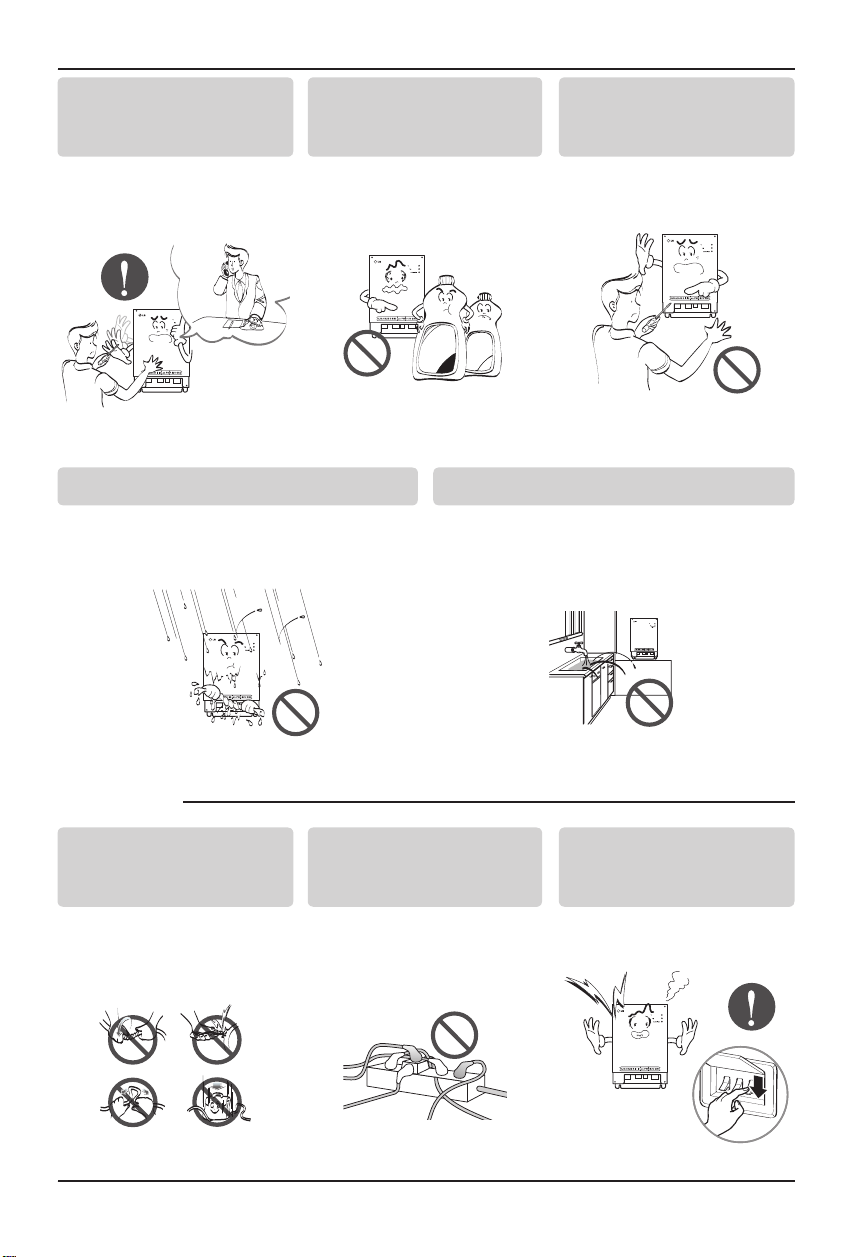
4
Lonworks 网关
安全注意事项
如果有水进入机器,关闭主机电源开关。
• 从插座上拔下电源插头,然后联系此产品服
务中心。
不要将此产品放置在潮湿的地方。
• 水会进入机器内部并降低机器的绝缘性能。
这样会有电击的危险。
BNU-LW
BNU-LW
■ 使用过程中
重新安装此产品时,请通知服
务中心或专卖店。
• 否则会导致事故、电击、爆
炸或造成人身伤害。
请不要在靠近易燃性气体或
易燃物如汽油、苯或稀释剂
附近使用电源线。
• 否则会导致爆炸或火灾。
请不要自行拆卸或维修和改
装此产品。
• 否则会引起火灾或电击。
BNU-LW
BNU-LW
Wa
x
Thinne
r
BNU-LW
请不要自行改装或延长导
线。
• 否则可能引起火灾或电击。
不要在一个插座连接过多电
源线。
• 否则可能引起火灾或电击。
如果此产品中发出怪声、气
味或烟雾,请立即拔下电源
插头。
• 否则可能引起火灾或电击。
BNU-LW
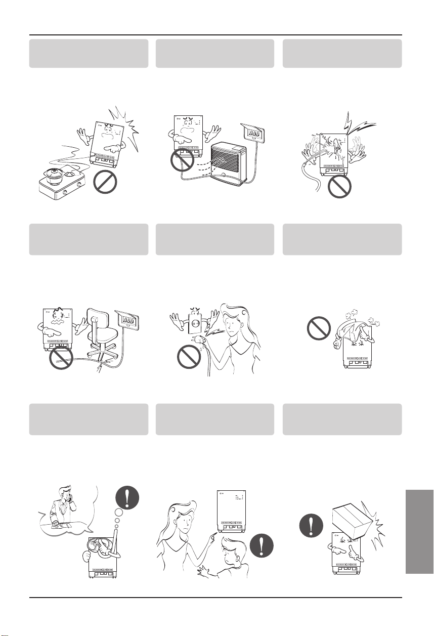
安装手册
5
CHINESE
安全注意事项
不要在此产品附近放置带明
火的设备。
• 否则可能引起火灾。
不要在此产品附件放置电热
器或导体。
• 否则可能引起火灾或电击。
不要使水溅到此产品内部。
• 否则可能导致电击和故障。
B
N
U
-L
W
BNU-LW
BNU-LW
不要在导线上放置重物。
• 否则可能引起火灾或电击。
在拔电源插头时请抓住其头
部将其拔出。
• 否则会导致电击和伤害。
不要在此产品上放置重物。
• 否则会导致产品故障。
BNU-LW
BNU-LW
当此产品遭水淹时请立即联
系服务中心或产品专卖店。
• 自行承担火灾和电击的责
任。
防止儿童操作此产品。
• 否则会导致事故和产品故
障。
不要使产品受到猛烈的撞
击。
• 自行承担产品被撞击而产生
的故障。
BNU-LW
BNU-LW
BNU-LW
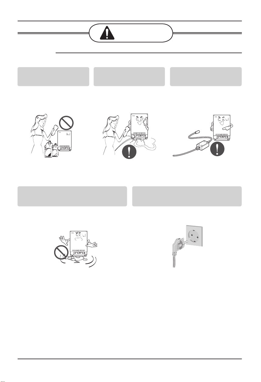
6
Lonworks 网关
安全注意事项
■ 使用过程中
用干净的软布轻轻清洁此
产品。
• 否则会导致火灾和产品变
形。
不要在有水的表面放置任何
带电物品。
• 否则会导致产品故障。
使用推荐的适配器。
• 否则会导致产品故障。
BNU-LW
W
ax
Thinner
BNU-LW
BNU-LW
BNU-LW
小 心
避免使金属物体如项链、硬币、钥匙、手表
等接触到电池。
• 否则会导致产品故障并造成伤害。
在拔电源插头时请抓住其头部将其拔出。
• 否则会导致电击和损坏。
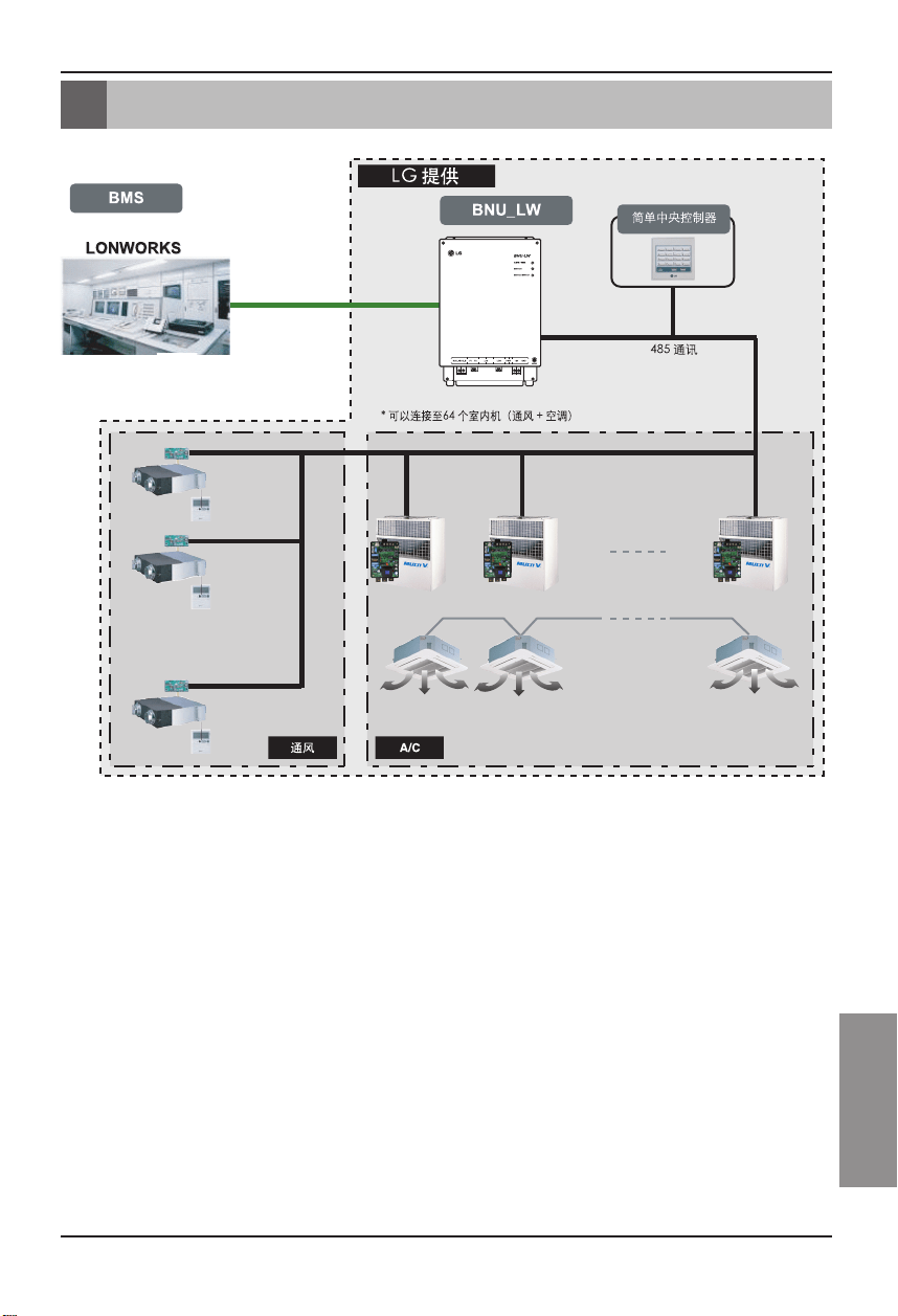
安装手册
7
CHINESE
总体系统图
总体系统图
* PNF-B16A1(Lon 网关)可以配合简单中央控制器使用。
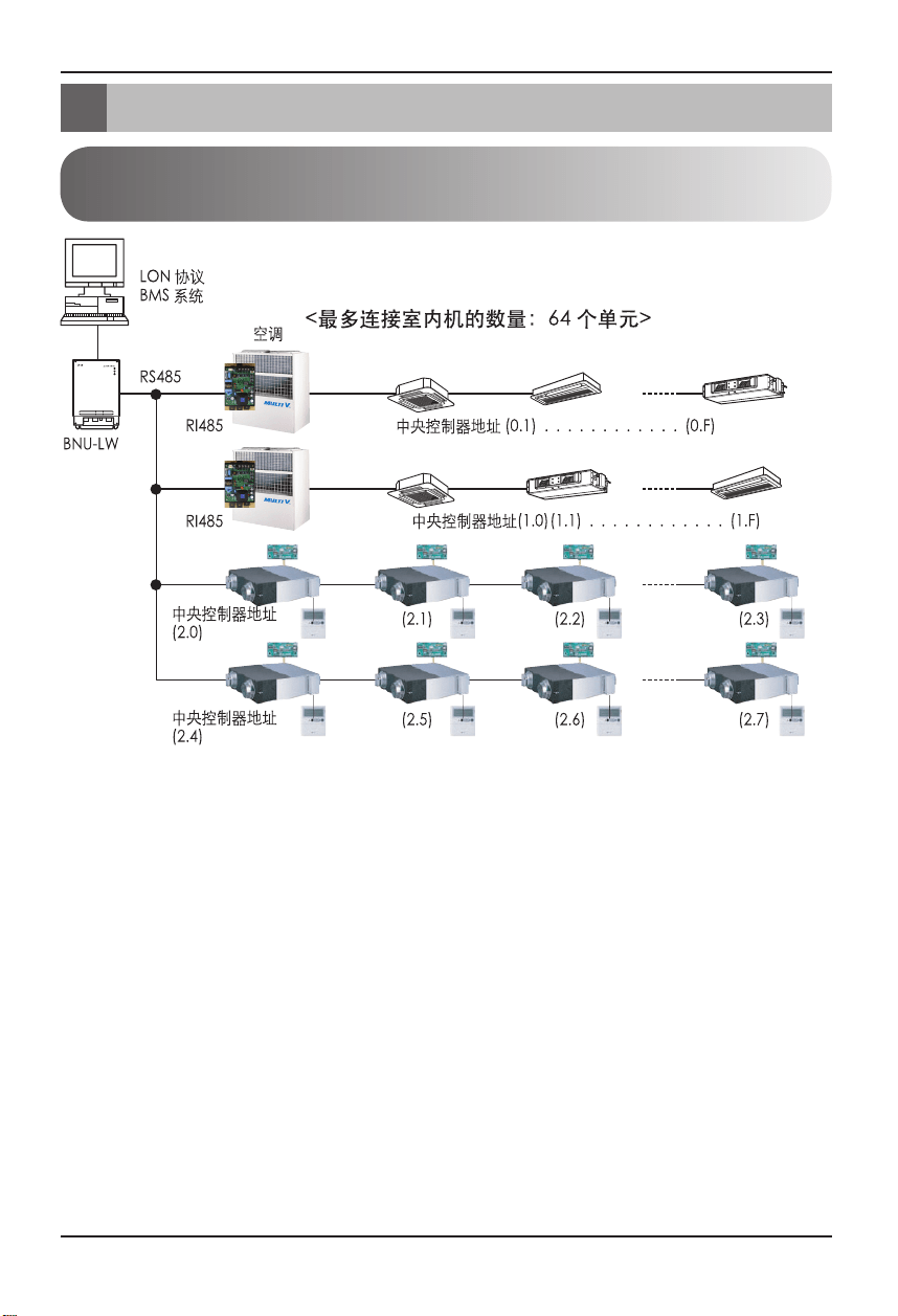
8
Lonworks 网关
外部接线图
• 当空调的室内机地址与通风机地址重复时,不能正常操作空调。
• BNU-LW 上最多可以连接 64 个室内机(空调 + 通风)。
• 推荐 BNU-LW 连接 16 个 PI485 单元,最多连接 32 个 PI485单元。
• 不能将通风设备连接到简单中央控制器上。
外部接线图
如何设置连接到BNU-LW(Lonworks 网关)
室内机的中央控制器的地址

安装手册
9
CHINESE
外部接线图
1. RS-485 通讯线路规格:0.75mm
2
或以上,2C 屏蔽,设备到设备:200M,总长度:1km
2. FT-10 通讯线路:参考下表
电缆类型 线规格 (AWG) 直径
TIA 568A Category 5 cable 24 0.5mm
Belden 88471 (PVC jacket) or equiva-
lent cable
16 1.3mm
Belden 85102(Tefzel) or equal cable 16 1.3mm
Level IV cable 22 0.65mm
JY (st) 2 x 2 x 0.8 20.4 0.8mm
• 节点到节点的距离(最大):250m,最远距离:450m
• AWG:美国线号规格
通讯线路规格
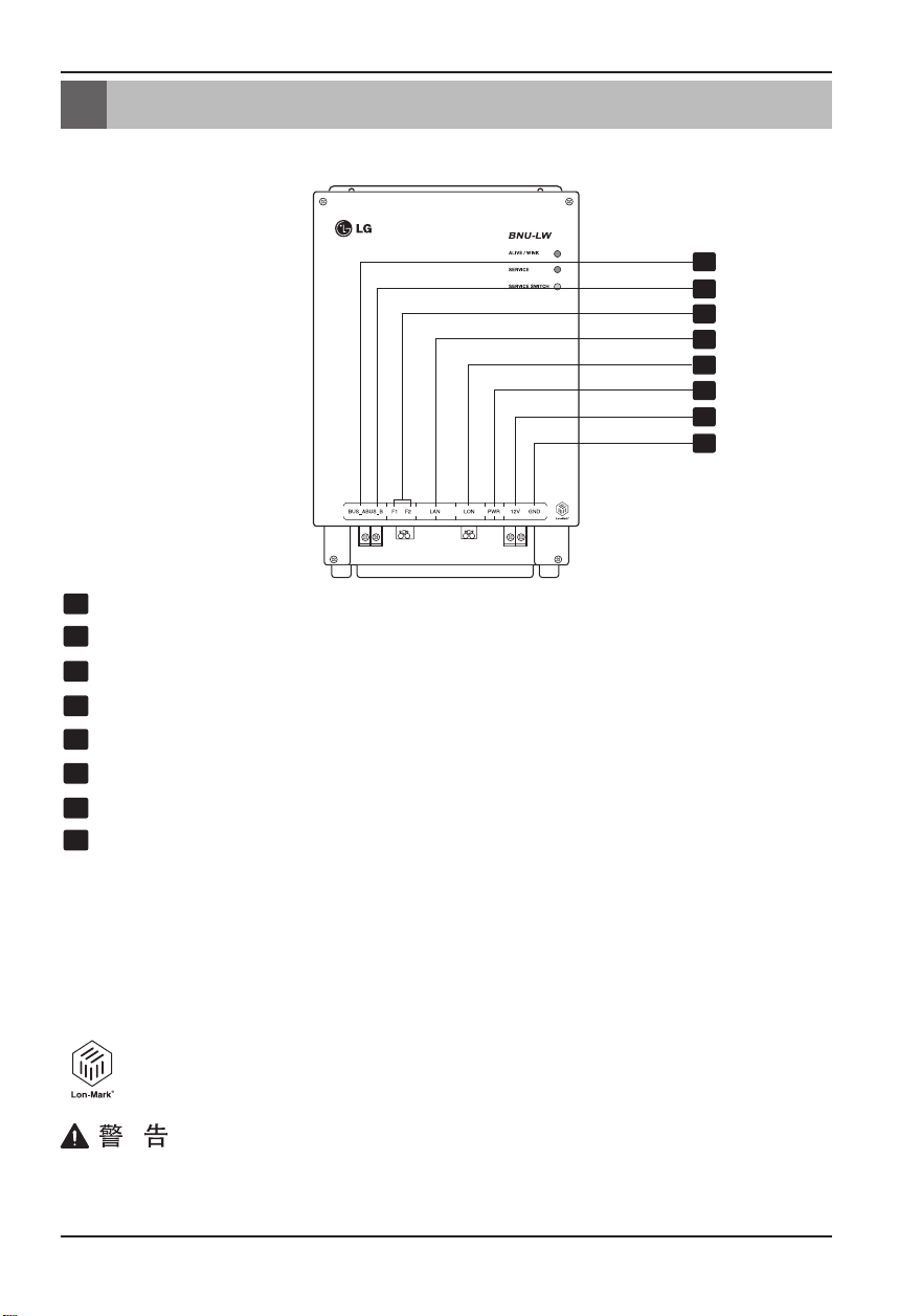
10
Lonworks 网关
各部件名称
各部件名称
1
2
3
4
5
6
7
8
BUS_A:485 通讯线路 A (+)
BUS_B:485 通讯线路 B (-)
F1、F2:火焰探测功能(外部设备)触点连接
LAN:网络功能需要的 LAN 端口
LON:TP/FT-10 通讯线路(Lonworks 系统通讯线路)无极性
PWR:连接到直流 12V 的电源适配器
12V:不使用直流 12V 电源适配器时连接
GND:不使用GNS 适配器时连接
ALIVE/WINK: 正常情况下每 1 秒钟闪烁一次
当接收到来自Lonworks 系统的 WINK 指令时,闪烁 5 次(绿色)
SERVICE: 正常时关闭,并在不能连接到 Lonworks 系统时闪烁。
按下服务开关时亮起。
SERVICE SWITCH: 按下开关时,将 Neuron ID 发送到 Lonworks 系统,
并且服务 LED 变亮。
BNU-LW (PNF-B16A1) 产品是满足 LON-MARK 标准的产品,符合国际标准。
(Lon Mark 3.3版)
1
2
3
4
5
6
7
8
9
10
11
12
13
1
2
3
4
5
6
7
8
9
10
11
12
13
1
2
3
4
5
6
7
8
9
10
11
12
13
1
2
3
4
5
6
7
8
9
10
11
12
13
1
2
3
4
5
6
7
8
9
10
11
12
13
1
2
3
4
5
6
7
8
9
10
11
12
13
1
2
3
4
5
6
7
8
9
10
11
12
13
1
2
3
4
5
6
7
8
9
10
11
12
13
Lonworks 网关
No. 6 和 No. 7,8 都用于电源供电。因此,只需要使用两种组合之一。
使用 DC 12V 作为电源时,将 No. 6 连接到电源(不需要使用 No. 7,8)。
不使用 DC 12V 作为电源时,将 No. 7,8 连接到电源(不需要使用 No. 6)。
安装手册
11
CHINESE
安装顺序
安装顺序
1. 根据室内机和 PI485 上 DIP S/W的中央控制器地址的设置安装设备。(将 DIP 开关 No. 4
设置为 ON)
(有关详细信息请参考 PI485 安装手册。)
2. 连接 BUS_A 和 BUS_B(485 通讯线路)时注意连接极性(参见下一页)。
3. LON(TP/FT-10 线路→Lonworks 网关通讯线路连接)TP/FT-10 通讯线路没有极性。
将 2 根通讯线连接到 BMS。
4. PWR(电源)
您可以选择两种电源中的任何一种。
➀ 使用直流 12V 电源适配器
连接到各个部件中名为 No. 6 的端子。
➁ 可以单独供应直流 12V 时
将 12V 和 GND 连接到 No. 7 和 8 端子。
5. 连接到 Lonworks 系统后按下服务开关时,服务 LED 点亮并且自动将 neuron ID 传送到
Lonworks 系统。
6. 在 10 分钟内检查服务 LED 是否处于正常状态(OFF 状态)。如果服务 LED 处于正常状
态,则已经正常完成安装。
7. 使用火焰探测端口时,将火焰探测传感器的两个端子连接到 F1 和 F2。
(火焰探测传感器必须用于 12V 或以下的直流输出。)
8. 安装后,连接 PC 间的局域网电缆,使用网络服务器。这样,可以检查 LG 设备是否已正常安
装。– 有关详细信息请参考远程诊断功能部分(第 16 页)。
将信号线连接到 Lonworks 网关端子时必须使用螺丝刀。
(注意切勿损坏端子块和 PCB。)
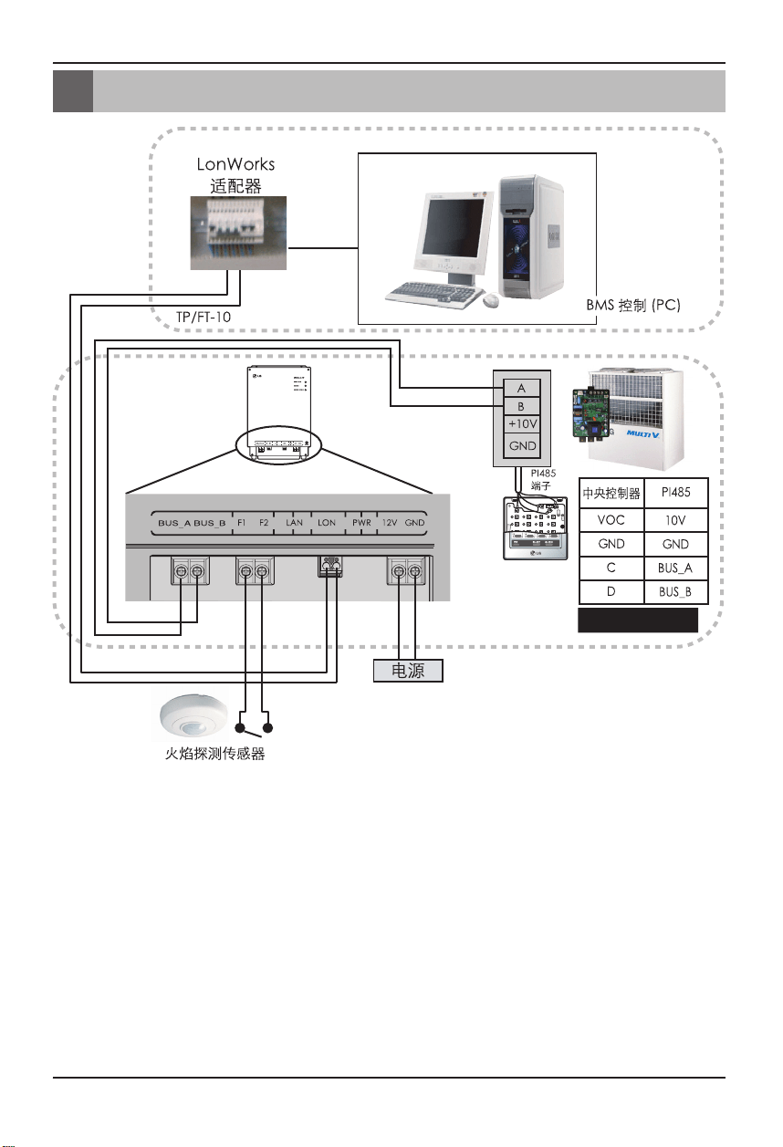
12
Lonworks 网关
BNU-LW 接线顺序
BNU-LW 接线顺序
LG 不提供这部分设备(连接和安装)
LG 提供
[接线顺序]
1. 连接 485 通讯线路
- 注意 BUS A 和 BUS B 的极性 (关于 485 G/
W 的信息请参考 DIP S/W 的 G/W 手册。)
2. 连接 Lonworks 通讯线路 (TP/FT-10)
- 无极性。
3. 电源(从 No. 1 或 2 中选择)
➀ 使用直流 12V适配器
- 连接到各个部件中名为 No. 6 的插孔。
➁ 为安装现场提供直流 12V 电源
- 将 12V 和 GND 连接到 No. 7 和 8 端子。
4. 连接到简单中央控制器
- 将简单中央控制器的 DIP S/W No. 2 设置为
ON 并根据旋钮 S/W 的地址配置设置。
(有关连接到简单中央控制器时的详细信息请
参考设置部分(第 20 页)。)
5. 连接火焰探测传感器
- 发生火灾的情况下,通过传送直流 12V 或以下
的信号,关闭连接到 BNU-LW 的所有室内机
和通风设备。
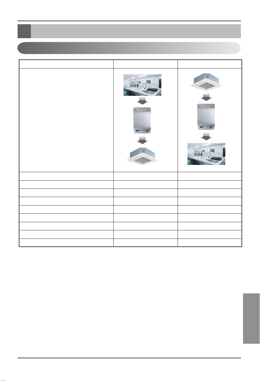
安装手册
13
CHINESE
空调/通风功能表
空调/通风功能表
空调室内机功能
绑定(连接)功能: 绑定功能指某单元的输出与另一单元输入的绑定情形,以及从更改输出到更改
输入的过程。使用其他制造商 Lon 单元可以实现绑定功能。
Ex) 当室内机 No. 1 的ON/OFF 输出与室内 No. 2的 ON/OFF 输出绑定,并且室内机 No. 1
开启时,室内机 No. 2 也在接收到信号时开启。
BMS
BNU-LW
BMS
BNU-LW
室内机单独控制 O O
更改操作模式 O O
更改风力等级 O O
温度调节功能 O O
锁定功能 O O
自动通风方向 O O
检查室内机温度 X O
故障检查 X O
同时操作/停止 O X
分类 控制 监视
功能
空调
空调
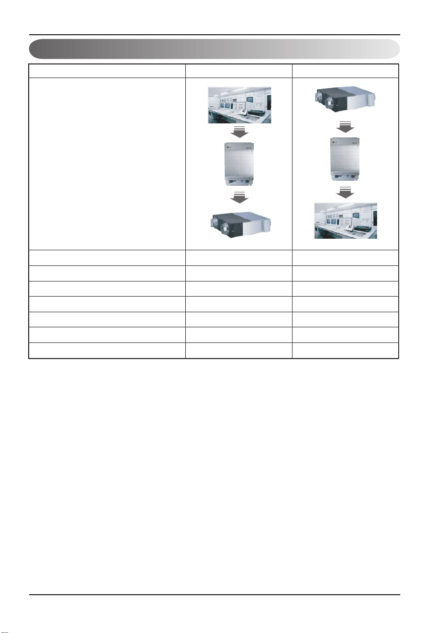
14
Lonworks 网关
空调/通风功能表
通风室内机功能
绑定(连接)功能: 绑定功能参考某单元的输出与另一单元输入的绑定情形以及从更改输出到更
改输入的过程。使用其他制造商 Lon 单元可以实现绑定功能。
Ex) 当室内机 No. 1 的ON/OFF 输出与室内 No. 2的 ON/OFF 输出绑定,并且室内机 No. 1
开启时,室内机 No. 2 也在接收到信号时开启。
BMS
BNU-LW
BMS
BNU-LW
Ventilation
Ventilation
室内机单独控制 O X
更改操作模式 O O
更改风力等级 O O
用户操作模式(快速通风、省电、制热) O O
锁定功能 O O
故障检查 X O
同时操作/停止 O X
分类 控制 监视
功能
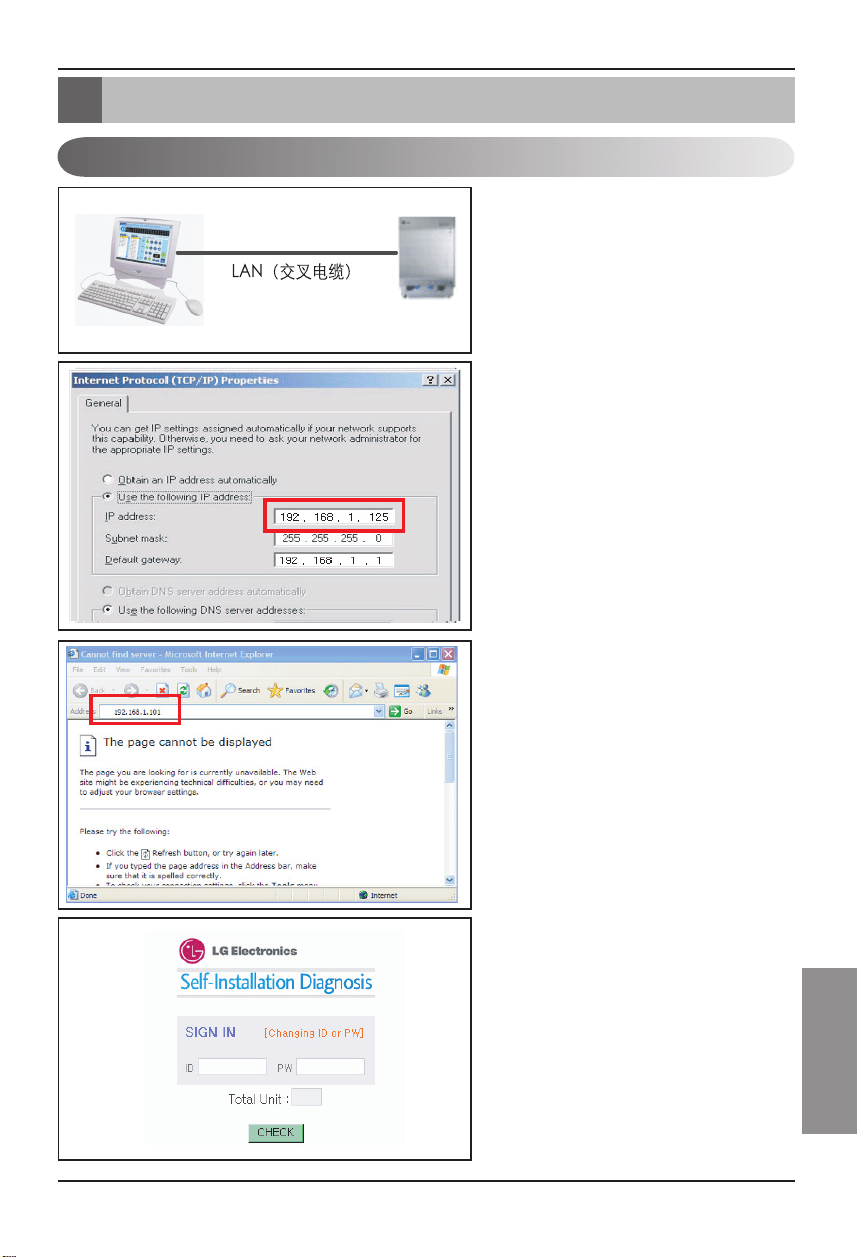
安装手册
15
CHINESE
BNU-LW 远程诊断功能
1. 连接 PC 和 BNU-LW 的 LAN 端口
之间的局域网线路。
2. 将所用 PC 的 IP 设置为
192.168.1.xxx(101 除外)。
3. 在 Internet Explorer 内输入
192.168.1.101。
4. 上图显示了正常连接时的情况。
• 初始 ID: lonwork
• 初始密码: lonwork
• 在 Total Unit 块内输入相连室内机
的总数。
BNU-LW 远程诊断功能
设置方法
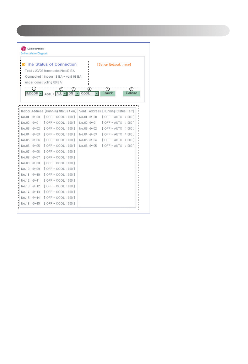
16
Lonworks 网关
BNU-LW 远程诊断功能
配置
• 输入 ID 和密码后,当前连接的空调
和通风设备如图所示。
• “A” 部分显示当前连接的空调和
通风设备的数量。
• 若要控制某设备➀ 选择设备 – ➁ 设
置地址 – ➂ 命令 ON/OFF – ➃ 选
择模式 – ➄ 单击检查以控制此设
备。
• 若要检查当前状态 ➅ 单击
Reload,将可以检查 “B” 部分内的
当前室内机状态。
• 若要更改 IP,单击 [Set up Network
place] 更改 IP。
"A"
"B"
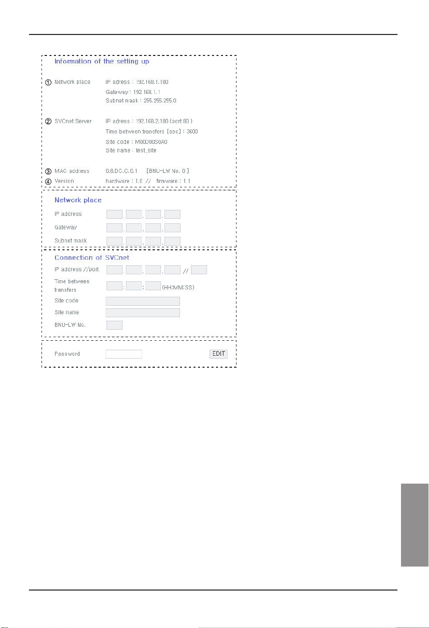
安装手册
17
CHINESE
BNU-LW 远程诊断功能
A
B
C
D
A: ➀ 显示当前的 IP、网关、子网
掩码信息。
➁ 若要使用 SVCNET
SERVER,将显示 SVCNET
SERVER 信息。
➂ 显示 MAC 地址信息。
➃ 显示 BNU-LW 的当前版本
信息。
B: 若要更改 IP 和网关、子网掩码
信息,请按下您要更改的信息旁
边的 EDIT 按钮。
C: 这是输入将要连接的 SVCNET
SERVER 信息的空间。
SVCNET SERVER 是通过局
域网监视连接到 BNU-LW 的
空调状态的服务,而且可以在
将来通过LG 电子服务中心
(LG ELECTRONICS SERVICE
CENTER) 在出现问题时及早提
供通知。
D: 为了防止网络更改或恶意篡
改,已为您提供了安全功能,需要
输入初始登录密码来更改网络
设置。
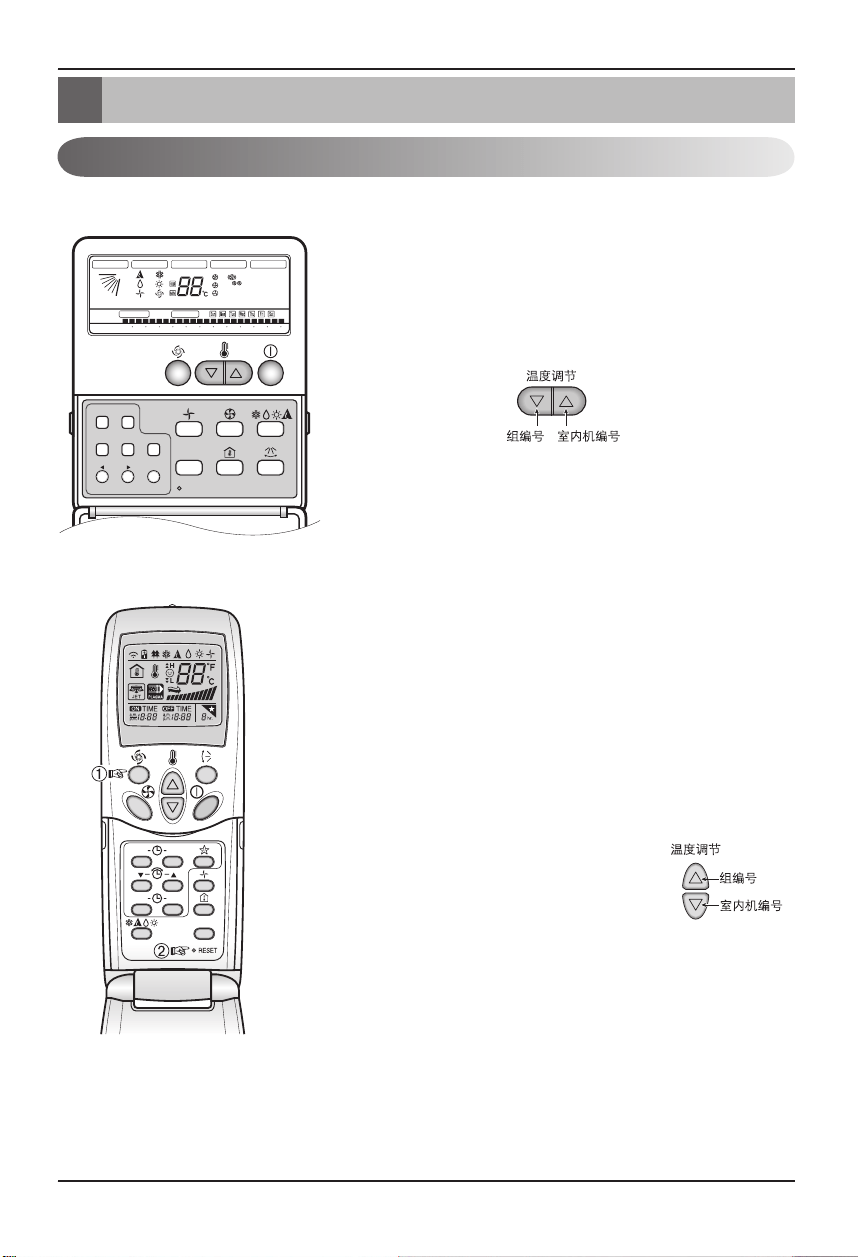
18
Lonworks 网关
设置室内机的地址
设置室内机的地址
设置室内机的地址
使用有线遥控器时
使用无线遥控器时
Timer Cancel
Program Week
Hour Mi
n
Holiday
Set/Clr
RESET
ZONE
1 2 3 4
Operation unit
Humidify
JET
AUTO
AUTO SWING
OPERATION
FAN SPEED
Program set
SUB FUNCTION
SET TEMP
Room Temp
HI
MED
LO
Heater
Defrost
Filter
Preheat
Out door
Time
Timer
On
Set no. Time
Off
01 03 05 07 09 11 13 15 17 19 21 23
Plasma
ON OFF
SET
CANCEL
PLASMA
Timer Cancel
Program Week
Hour Mi
n
Holiday
Set/Clr
RESET
ZONE
1 2 3 4
Operation unit
Humidify
JET
AUTO
AUTO SWING
OPERATION
FAN SPEED
Program set
SUB FUNCTION
SET TEMP
Room Temp
HI
MED
LO
Heater
Defrost
Filter
Preheat
Out door
Time
Timer
On
Set no. Time
Off
01 03 05 07 09 11 13 15 17 19 21 23
Plasma
1. 同时按下工作日和预约设置/取消按钮 3 秒钟。
2. 使用温度调节按钮设置室内机地址。
设置范围:00~FF
3. 同时按下工作日和预约设置/取消按钮 3 秒钟后,地址设置完成。
地址设置模式
1. ➀ 按住左上方按钮持续至少 3 秒钟。➁ 在按下左上方按钮时,按
动复位 (Reset) 按钮。
※不同机型所配置的无线遥控器的外形也不同。
2. 使用温度调节按钮设置室内机地址。
设置范围:00~FF
3. 设置好地址后,对准室内机按一次 ON/OFF 按钮。
4. 室内机将显示设置的地址,完成地址设置。
(地址显示时间和方式因室内机类型而异。)
5. 将遥控器复位到常规操作模式。
地址检查模式
1. 在按下右上方按钮时,按动复位 (Reset) 按
钮。(按住此左侧按钮持续至少 3 秒钟。)
2. 对准室内机按一次 ON/OFF 按钮,室内机将
在显示窗口显示设置的地址。
(地址显示时间和方式因室内机类型而异。)
3. 将遥控器复位到常规操作模式。
❈ 根据有线/无线遥控器的生产日期,某些遥控器可能无法完成以上功能。
不过这对用户来说没有关系,在安装期间您可以使用具有地址设置功能的遥控器来设置地址。
Timer Cancel
Program Week
Hour Mi
n
Holiday
Set/Clr
RESET
ZONE
1 2 3 4
Operation unit
Humidify
JET
AUTO
AUTO SWING
OPERATION
FAN SPEED
Program set
SUB FUNCTION
SET TEMP
Room Temp
HI
MED
LO
Heater
Defrost
Filter
Preheat
Out door
Time
Timer
On
Set no. Time
Off
01 03 05 07 09 11 13 15 17 19 21 23
Plasma
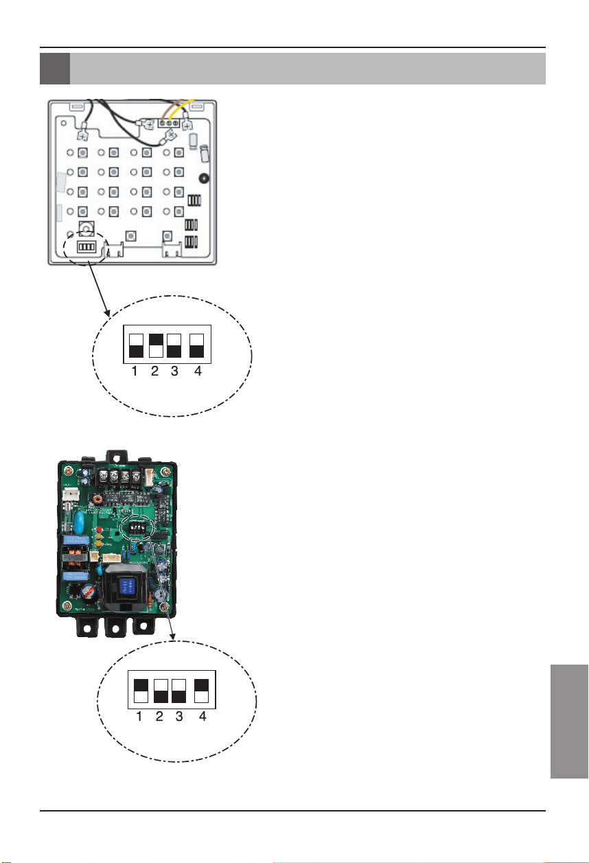
安装手册
19
CHINESE
连接到简单中央控制器
连接到简单中央控制器
如何连接简单中央控制器
• 当连接到简单中央控制器时,将简单中央控制器的 DIP S/W
No. 2 切换到 ON 的位置。
• 将旋钮 S/W 设置为您希望控制的室内机的组地址。
如何设置PI-485
如何设置PI-485
• BNU-LW 使用 LGAP 通讯协议。
可以将 PI-485 的 DIP S/W No. 1 和 No. 4
切换到 ON 的位置。
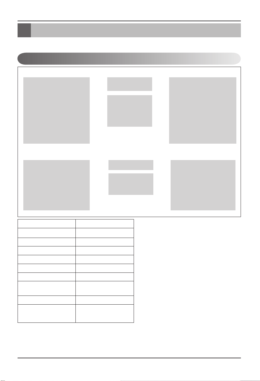
20
Lonworks 网关
附录
附录
A/C 对象
• 附录中提供了连接 BMS 以及与实际安装不太相关的必要信息。
标准功能块
SNVT
_
switch nviOnOff
SNVT
_
hvac
_
mode nviHeatCool
SNVT
_
switch nviFanSpeedcmd
SNVT
_
switch nviLock
SNVT
_
switch nviSwing
SNVT
_
switch nviSetPoint
SNVT
_
switch nviUser
SNVT
_
switch nviSpaceTemp
SNVT
_
switch nvoOnOff
SNVT
_
hvac
_
mode nvoHeatCool
SNVT
_
switch nvoFanSpeed
SNVT
_
switch nvoLock
SNVT
_
switch nvoSwing
SNVT
_
temp
_
P nvoSetPoint
SNVT
_
hvac
_
status nvoUnitStatus
SNVT
_
count nvoUser
SCC(8500)FB
Indoor/
Ventilator unit
Network Varlables
SWITCH(3200)FB
Total
Control
SNVT
_
switch
nviTotalOnOff
_
Indoor
SNVT
_
switch
nviTotalOnOff
_
Vent
SNVT
_
switch nvoSwitch
• 如图所示,可以进行单个空调/通风机的控制和监视。
• 网络变量可能与实际情况不太一样。
(请参阅 XIF 文件了解正确的网络变量。)
➔
➔
➔
➔
控 制 监 视
On/Off 命令 On/Off 状态监视
模式选择命令 模式状态监视
风力等级选择命令 风力等级状态监视
室内机锁定命令 锁定状态监视
风向命令 风向状态监视
温度设置命令 温度设定状态监视
通风附加功能命令
(仅适用于通风设备)
当前的温度监视
空调总 On/Off 控制 故障显示
通风总 On/Off 控制
通风附加功能状态监视
(仅适用于通风设备)
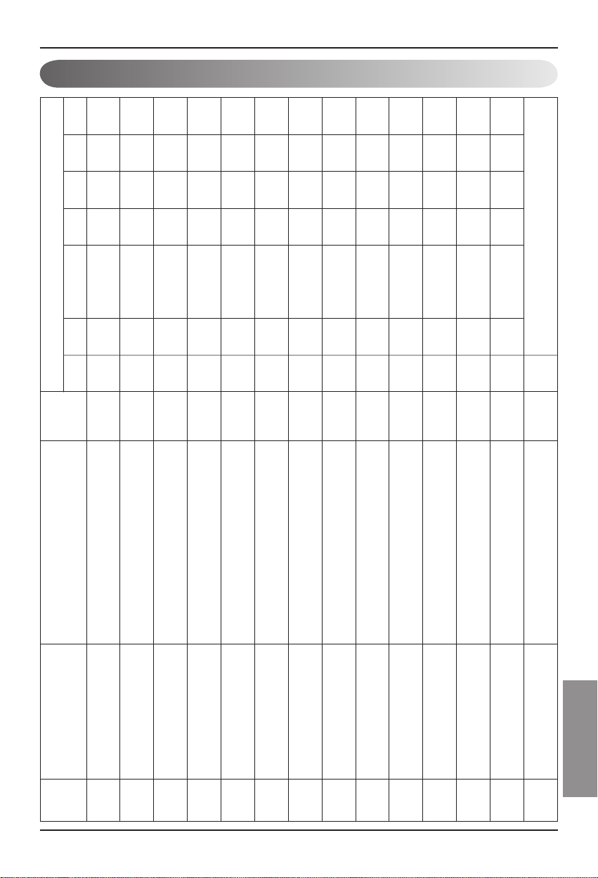
安装手册
21
CHINESE
附录
空调控制/监视点
1 开/关(设置) SNVT_switch nviOnOff_nn 输入 停止
操作
2 开/关(状态) SNVT_switch nvoOnOff_nn 输出 停止
操作
3 锁定(设置) SNVT_switch nviLock_nn 输入 取消 设置
4 锁定(状态) SNVT_switch nvoLock_nn 输出 取消 设置
5 运行模式(设置) SNVT_hvac_modenviHeatCool_nn 输入 自动 制热 制冷 风扇
弱
6 运行模式(状态) SNVT_hvac_mode nviHeatCool_nn 输出 自动 制热 制冷
风扇
弱
7 摆风(状态) SNVT_switch nviSwing_nn 输入 取消 设置
8 摆风(设置) SNVT_switch nvoSwing_nn 输出 取消 设置
9 风扇速度(设置) SNVT_switch nviFanSpeedCmd_nn 输入 低 中 高 自动 风扇
10 风扇速度(状态) SNVT_switch nvoFanSpeed_nn 输出 低 中 高 自动 风扇
11 设置房间温度 SNVT_temp_p nviSetPointCmd_nn 输入 °C
12 设置房间温度 SNVT_temp_p nvoSetPoint_nn 输出 °C
13
房间温度
SNVT_temp_p nvoSpaceTemp_nn 输出 °C
14 故障代码 SNVT_hvac_status nvoUnitStatus_nn 输出 无故障
请参见 LG 空调故障代码 (LG Air Conditioner Error Code)。
点数 名称 对象类型
单位
代码0 代码1 代码2 代码3 代码4 代码5 代码9 代码14
对象名称
(nn:空调和通风组/室内机的地址)

22
Lonworks 网关
附录
通风控制/监视点
1 开/关(设置) SNVT_switch nviOnOff_nn 输入 停止 操作
2 开/关(状态) SNVT_switch nvoOnOff_nn 输出 停止 操作
3 锁定(设置) SNVT_switch nviLock_nn 输入 取消 设置
4 锁定(状态) SNVT_switch nvoLock_nn 输出 取消 设置
5 运行模式(设置) SNVT_hvac_modenviHeatCool_nn 输入 自动 制热 正常
6 运行模式(状态) SNVT_hvac_mode nviHeatCool_nn 输出 自动 制热 正常
7 风扇速度(设置) SNVT_switch nviFanSpeedCmd_nn 输入 低 高 极高
8 风扇速度(状态) SNVT_switch nvoFanSpeed_nn 输出 低 高 极高
9 故障代码 SNVT_hvac_status nvoUnitStatus_nn 输出
请参见 LG 空调故障代码 (LG Air Conditioner Error Code)。
10 用户模式(设置) SNVT_count nviUser_nn 输出 快速
省电
加热
11 用户模式(状态) SNVT_count nvoUser_nn 输出 快速
省电
加热
点数
名称
对象类型
单位
代码0 代码1 代码2 代码3 代码5 代码9
对象名称
(nn:空调和通风组/室内机的地址)
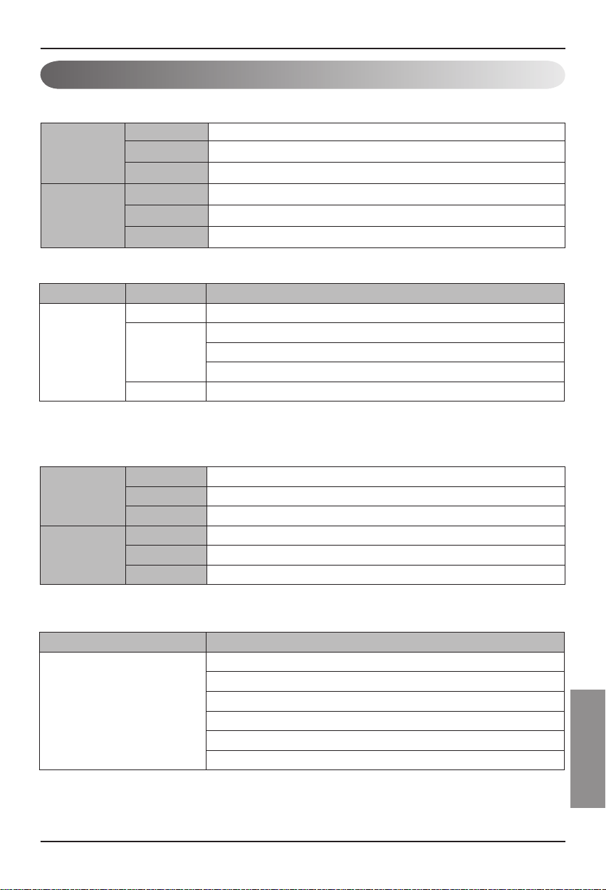
安装手册
23
CHINESE
附录
网络变量
1) 单独操作/停止输入/输出(空调/通风)
功能 操作/停止输入
输入 使用 NV 网络输入变量 : SNVT_switch nviOnOff_n
操作 它控制各个设备(空调/通风)的操作/停止
功能 操作/停止状态显示
输出 使用 NV 网络输出变量 : SNVT_switch nvoOnOff_n
操作 它监视各个设备(空调/通风)的操作状态
2)操作模式输入/输出(空调/通风)
有效范围
NV 字段 操作
SNVT_
switch(index
: 95)
值 未使用(通常设置在 0%)
状态
0 = 空调/通风设备 OFF
1 = 空调/通风设备 ON
默认值
输入
功能 操作模式命令输入
使用 NV 网络输入变量 : SNVT_hvac_mode nviheatCool_n
操作
It controls the operating mode of each air conditioner/ventilation product.
输出
功能 它控制各个空调/通风设备的操作模式
使用 NV 操作模式状态显示 : SNVT_hvac_mode nvo HeatCool_n
操作
It controls the operating mode of each air conditioner/ventilation product.
NV 操作
SNVT_hvac_mode(index : 108)
HVAC_AUTO:0 = 自动模式 (auto), 自动通风
HVAC_HEAT:1 = 加热模式 (heat), 加热通风
HVAC_COOL:3 = 制冷模式 (cool)
HVAC_FAN_ONLY:9 = 通风模式 (fan), 正常通风
HVAC_DEHUMID:14 = 干燥模式(除湿)
默认值
有效范围
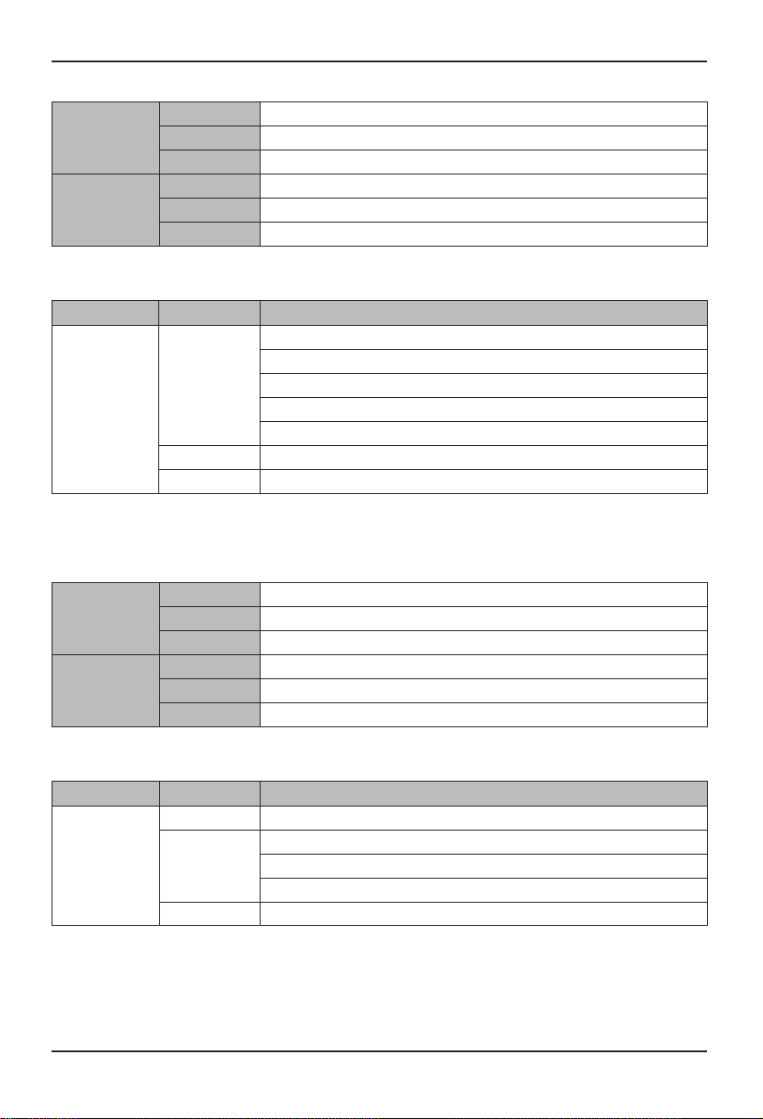
24
Lonworks 网关
附录
3) 风力等级命令输入/输出(空调/通风)
有效范围
有效范围
4) 锁定输入/输出(空调/通风)
输入
功能 风力等级命令输入
使用 NV 网络输入变量 : SNVT_switc nviFanSpeedCmd_n
操作
它控制各个室内机的风力等级。
输出
功能 风力等级状态显示
使用 NV 操作模式状态显示 : SNVT_switch nvoFanSpeed_n
操作
它监视各个设备(空调/通风)的风力等级)
NV 字段 操作
SNVT_
switch(index
: 95)
值
1: 空调、通风低风力
2: 空调中等风力、通风高风力
3: 空调高风力、通风极高风力
4: 空调、通风自动风力
5. 空调、通风极低风力
状态 0: 未启用设备,1:已经启用设备
默认值
输入
功能
锁定设置命令输入
使用 NV
网络输入变量 : SNVT_switch nviLock_n
操作
它控制各个设备(空调/通风)的锁定状态
输出
功能
锁定状态显示
使用 NV
网络输出变量 : SNVT_switch nvoLock_n
操作
它监视各个设备(空调/通风)的锁定状态
NV 字段 操作
SNVT_switch
(index : 95)
值 未使用(通常设置在 0%)
状态
0 = 空调/通风设备锁定 OFF
1 = 空调/通风设备锁定 ON
默认值
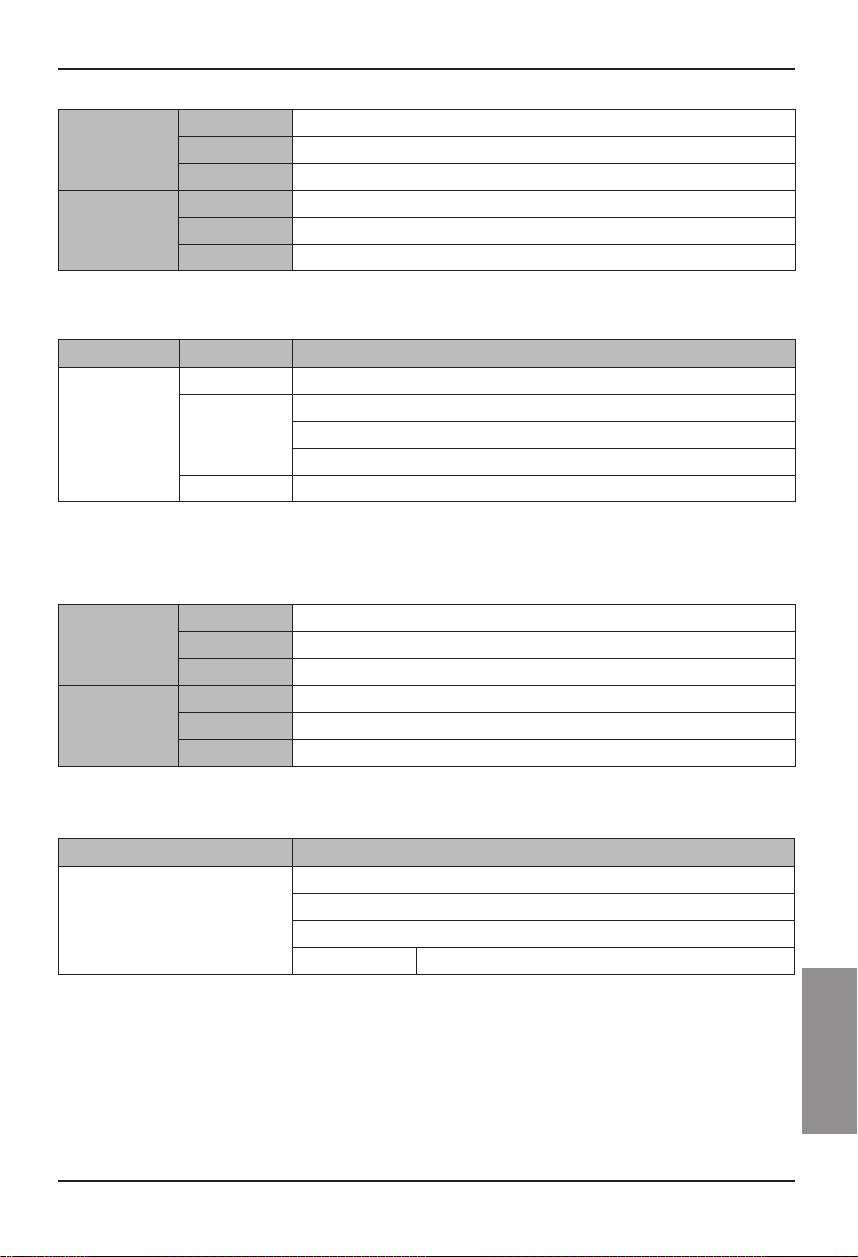
安装手册
25
CHINESE
附录
有效范围
5) 风向自动输入/输出(仅适用于空调)
6) 温度设定输入/输出(仅适用于空调)
有效范围
输入
功能
风向自动命令输入
使用 NV
网络输入变量 : SNVT_switch nviSwing_n
操作
它控制各个设备(空调/通风)的风向
输出
功能
风向自动状态显示
使用 NV
网络输出变量 : SNVT_switch nvoSwing_n
操作
它监视各个设备(空调/通风)的风向
NV 字段 操作
SNVT_switch
(index : 95)
值 未使用(通常设置在 0%)
状态
0 = 空调设备的风向固定
1 = 空调设备的风向自动
默认值
输入
功能
设置温度范围输入
使用 NV
网络输入变量 : SNVT_switch nviSetPoint_n
操作
它控制各个设备(空调/通风)的温度设置
输出
功能
设置温度范围状态显示
使用 NV
网络输出变量 : SNVT_switch nvoSetPoint_n
操作
它监视各个设备(空调/通风)的设定温度
NV 操作
SNVT_switch(index : 95)
制冷模式:18~30°C
制热模式:18~30°C
除湿模式和风扇模式:不可用
默认值
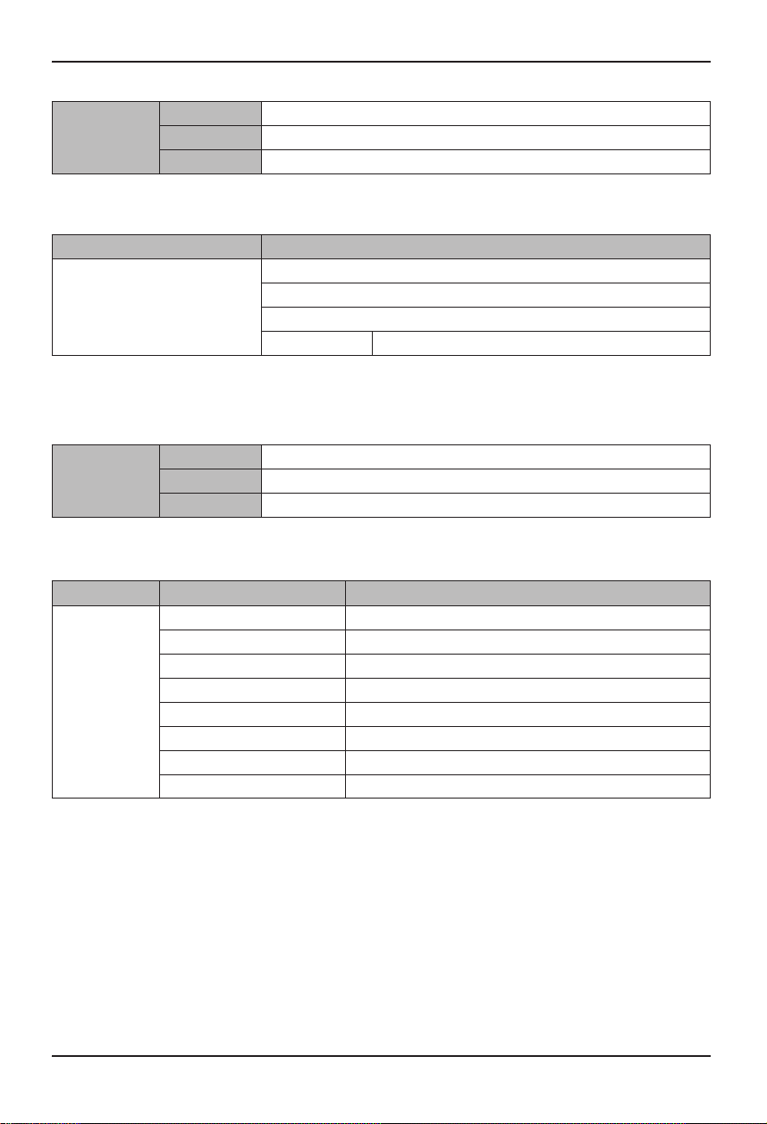
26
Lonworks 网关
附录
7) 室内温度状态显示(仅适用于空调)
8) 故障输出(空调/通风)
有效范围
有效范围
* 请参见设备手册的故障代码表,了解故障代码的信息。
输出
功能 室内温度状态显示
使用 NV 网络输出变量 : SNVT_switch nvoSpaceTemp_n
操作 它监视室内的温度
NV 操作
SNVT_switch(index : 95)
制冷模式:10~40°C
制热模式:10~40°C
除湿模式和风扇模式:不可用
默认值
输出
功能 故障状态显示
使用 NV 网络输入变量 : SNVT_hvac_Status nvoUnitStatus_n
操作 它监视各个设备(空调/通风)的故障状态
NV 字段 操作
SNVT_switch
(index : 112)
模式 当前的操作模式显示
Heat_output_primary 未使用
Heat_output_Secondary 未使用
Cool_output 未使用
Cool_output 未使用
Econ_output 未使用
Fan_output 未使用
In_alarm 故障代码显示
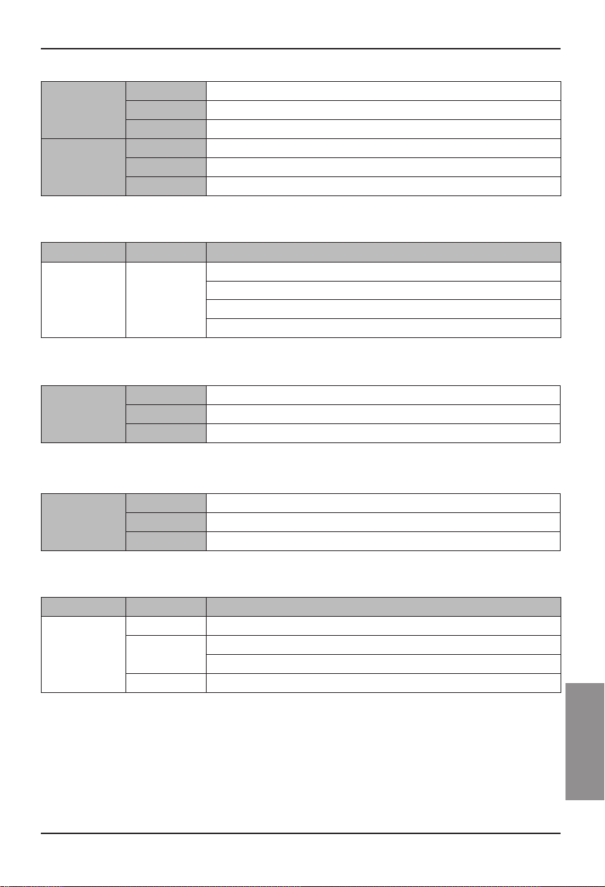
安装手册
27
CHINESE
附录
10) 总操作/停止空调室内机
11) 总操作/停止通风室内机
有效范围
9) 通风功能命令(仅适用于通风设备)
有效范围
输入
功能
通风用户操作模式输入
使用 NV
网络输入变量 : SNVT_count nviuser_n
操作
它控制各个通风设备的设备功能。
输出
功能
通风用户操作模式状态
使用 NV
网络输出变量 : SNVT_count nvoUser_n
操作
它监视各个通风设备的功能状态。
NV 字段 操作
SNVT_count
(index : 8)
值
0 = 不使用
1 = 快速模式
2 = 省电模式
3 = 加热
输出
功能 总停止命令输入
使用 NV 网络输入变量 : SNVT_switch nviTotalONOFF_indoor
操作 它打开或者关闭所有的室内机。
输出
功能 总停止命令输入
使用 NV 网络输入变量 : SNVT_switch nvTotalONOFF_indoor
操作 它打开或者关闭所有的通风机。
NV 字段 操作
SNVT_switch
(index : 95)
值 未使用
状态
1 = 打开所有室内机/通风设备
0 = 关闭所有室内机/通风设备
默认值

P/No.: 3828A20494S
After reading this manual, keep it in a place easily accessible to the user for future reference.
Printed in Korea