Loading ...
Loading ...
Loading ...
Abluftrohr Ø 120 mm
1. Reduzierstutzen direkt am Luftstutzen befestigen.
2. Abluftrohr am Reduzierstutzen befestigen.
3. Beide Verbindungsstellen geeignet abdichten.
Rohrmaße
Hinweis: Für Beanstandungen, die auf die Rohrstrecke zurück-
zuführen sind, übernimmt der Hersteller des Gerätes keine
Gewährleistung.
■ Das Gerät erreicht seine optimale Leistung durch ein kurzes,
geradliniges Abluftrohr und einen möglichst großen
Rohrdurchmesser.
■ Durch lange raue Abluftrohre, viele Rohrbögen oder
Rohrdurchmesser, die kleiner als 150 mm sind, wird die
optimale Absaugleistung nicht erreicht und das Lüfter-
geräusch wird lauter.
■ Die Rohre oder Schläuche zum Verlegen der Abluftleitung
müssen aus nicht brennbarem Material sein.
Rundrohre
Es wird ein Innendurchmesser von 150 mm empfohlen, jedoch
mindestens 120 mm.
Flachkanäle
Der Innenquerschnitt muss dem Durchmesser der Rundrohre
entsprechen.
Ø 150 mm ca. 177 cm
2
Ø 120 mm ca. 113 cm
2
■ Flachkanäle sollten keine scharfen Umlenkungen haben.
■ Bei abweichenden Rohrdurchmessern Dichtstreifen einsetzen.
Gerät anschließen
Schließen Sie die Muldenlüftung an den Gebläsebaustein oder
das Umluftmodul durch den 6-poligen Stecker an.
en
Ú Installation instructions
Important notes
Read these instructions carefully and keep them in a safe place.
Safety during use can only be ensured if the appliance is fitted
correctly according to these installation instructions. The
installer is responsible for ensuring that the appliance operates
perfectly at the point of installation.
The appliance must be connected to the mains only by a
licensed and trained technician.
Before carrying out any type of work, turn off the electricity.
For installation, currently applicable building regulations and the
regulations of local electricity and gas suppliers must be
observed (e.g. Germany: DVGW-TRGI/TRGF; Switzerland:
SVGW; Austria: ÖVGW-TR).
This appliance corresponds to appliance class 3 (for installation
in a kitchen unit). It must be fitted according to the installation
drawing. Observe the minimum distance to side walls or
furniture parts and to the rear wall.
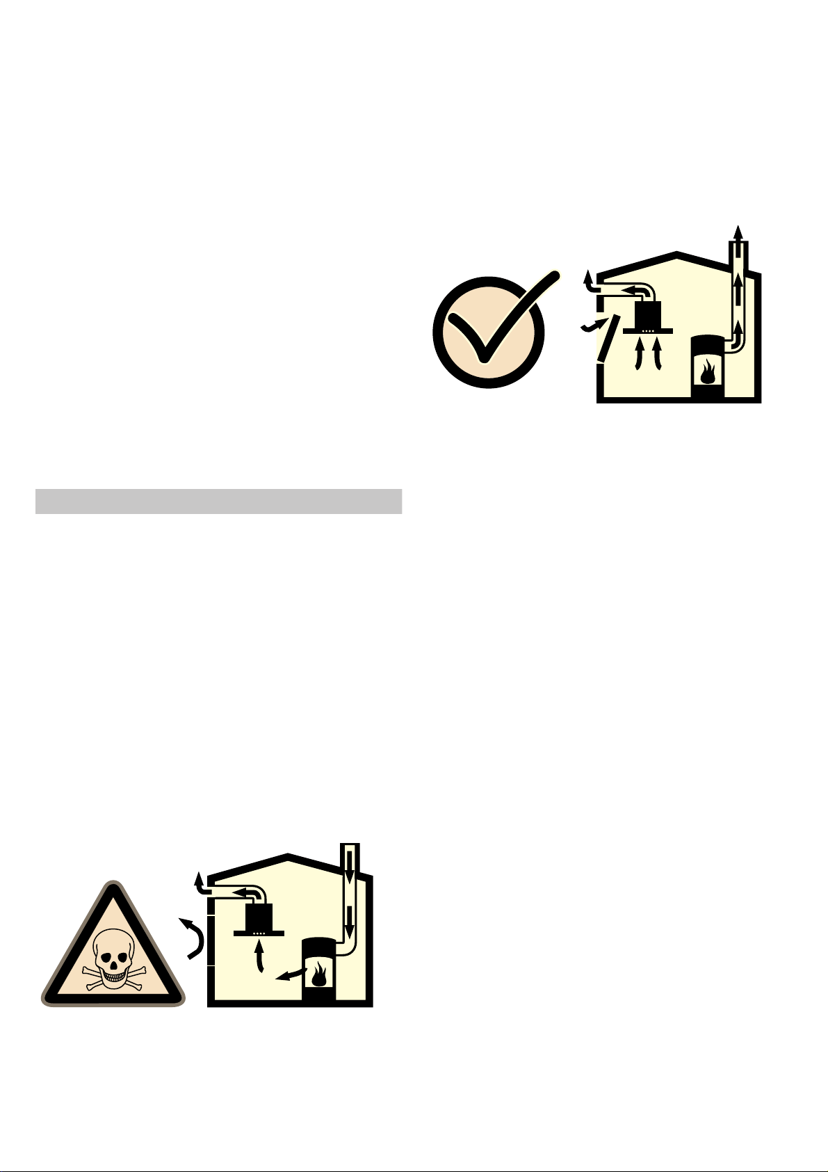
Safety notes
Mortal danger, risk of intoxication!
Due to combustion gases sucked back in. Never operate the
appliance in the exhaust air mode at the same time as a room
air-dependent heat-producing appliance unless an adequate
supply of fresh air is ensured.
Room air-dependent heat-producing appliances (e.g. gas, oil,
wood or coal-operated heaters, continuous flow heaters or water
heaters) obtain combustion air from the room in which they are
installed and discharge the exhaust gases into the open through
an exhaust gas system (e.g. a chimney).
In combination with an activated vapour extractor hood, room air
is extracted from the kitchen and neighbouring rooms - a partial
vacuum is produced if not enough fresh air is supplied. Toxic
gases from the chimney or the extraction shaft are sucked
backed into the living space.
■ Adequate incoming air must therefore always be ensured.
■ An incoming/exhaust air wall box alone will not ensure
compliance with the limit.
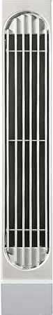
Safe operation is possible only whenever the partial vacuum in
the place where the firing equipment is installed does not
exceed 4 Pa (0.04 mbar). This can be achieved whenever the
air needed for combustion is able to enter through openings
that cannot be sealed, for example in doors, windows,
incoming/exhaust air wall boxes or by other technical means.
In any case, consult your responsible chimney sweep. He is
able to assess the house's entire ventilation setup and will
suggest the suitable ventilation measures to you.
Unrestricted operation is possible if the vapour extractor hood is
operated exclusively in the recirculation mode.
Risk of injury!
From sharp edges during installation. Always wear protective
gloves while installing the appliance.
Fire risk!
An air baffle (LS 041 000) must be used if the hob ventilators VL
040/041 are operated next to a gas appliance. In this way, the
flame cannot be drawn into the ventilator. This avoids ignition of
a filter impregnated with grease by the gas flame.
Preparing the furniture
The surrounding kitchen unit must be heat-resistant to at least
90 °C. The stability of the unit must be maintained after
producing the cut-out.
Produce the cut-out for one or several Vario appliances.
Proceed as shown in the installation sketch. The angle between
the cut surface and the worktop must be 90°.
After producing the cut-out, remove the shavings. Seal the cut
surfaces to make them heat-resistant.
Observe a minimum clearance between the appliance housing
and parts of the unit of 10 mm.
When fitting several Vario appliances: allow for the additional
space required for the connecting strip VV 200. Appliances can
also be fitted in individual recesses, if a minimum clearance of
40 mm between the appliances is observed.
Electrical connection
Check the electrical installation system before connecting the
appliance. Make sure that the household installation has
sufficient fuse or circuit breaker protection. Check that the
appliance has the same voltage and frequency as the electrical
installation system (see rating plate).
The appliance corresponds to protection class I and may only
be operated with a protective earth connection.
The installation system must incorporate an all-pole isolating
switch with a contact gap of at least 3 mm, or the appliance
should be connected to the mains via a safety plug. The plug
must remain accessible after installation.
Recommendation: install a properly earthed socket behind the
appliance, approx. 70 cm above the floor.
Only a qualified electrician who takes the appropriate
regulations into account may connect a socket.
Only connect the appliance with the supplied mains connection
cable.
Do not kink or trap the mains connection cable.
The appliance corresponds to type Y: the mains connection
cable must only be replaced by the after-sales service. Check
the cable type and minimum cross section.
Loading ...
Loading ...
Loading ...