Loading ...
Loading ...
Loading ...
34
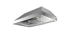
Panneau de commande de Rangehood
Le panneau de commande est plac au centre du
fond de capot.
Bouton "Marche/Arrêt" léger (A)
Interrupteur Marche/Arrêt pour l'éclairage. La po-
sition « 0 » éteint l’éclairage, tandis que l’éclairage
est mis en marche si l’interrupteur est tourné vers
la droite.
Bouton "Marche/Arrêt" de ventilateur (B)
Commutateur "Marche/Arrêt" pour le ventilateur.
Déplacez le cadran vers la droite d'allumer le
ventilateur et de varier la vitesse du ventilateur.
Tournez-vous vers la gauche au " ; 0" ; pour
l'arrêter.
Pour le meilleur résultat
Commencez le rangehood plusieurs minutes avant
la cuisson pour développer le ux d'air approprié.
Permettez à l'unité de fonctionner pendant
plusieurs minutes après cuisson est complet pour
dégager toutes les fumée et odeurs de la cuisine.
Nettoyage
Les ltres de graisse d'acier inoxydable et le rail de
graisse devraient être nettoyés fréquemment dans
la solution détersive chaude ou être lavés dans le
lave-vaisselle. Nettoyez les surfaces extérieures
avec un décapant disponible dans le commerce
d'acier inoxydable. Les abrasifs et les agents
de récurage peuvent rayer des nitions d'acier
inoxydable et ne devraient pas être employés pour
nettoyer les surfaces de nition.
Graissez l'installation de ltre de rail et de
graisse/déplacement
Éliminez le plastique du ltre, les boutons
doivent être installés sur le ltre avec 2 vis sur
chaque ltre.
Version 07/11 - Page 11
Light On/Off Button (A)
On/Off switch for the halogen lights. Position "0" turns the lights off,
turning the switch to the right one click is the dimmer position, and
the next click to the right is full power
Blower On/Off Button (B)
On/Off switch for the blower. Move the dial to the right to turn the
blower ON and vary the speed of the blower. Turn to the left at "0"
to turn it OFF.
For Best Result
Start the rangehood several minutes before cooking to develop proper
airflow. Allow the unit to operate for several minutes after cooking is
complete to clear all smoke and odors from the kitchen.
Cleaning
The stainless steel grease filters and grease rail should be cleaned
frequently in hot detergent solution or washed in the dishwasher.
Clean exterior surfaces with a commercially available stainless steel
cleaner. Abrasives and scouring agents can scratch stainless steel
finishes and should not be used to clean finished surfaces.
Grease rail and Grease Filter Installation / Removal
Remove the plastic from the filter, the knobs need to be installed
onto the filter with 2 screws to each filter
Install the grease rail into the back of the hood, into the slots on the
inside floor of the rear of the hood. The Grease filters should be
installed before operating the rangehood. To install the filters, use the
two knobs (in FIGURE 28) to hold the filter and insert the filter into
the front edge of the hood with the knobs facing out into the spring
loaded slot. Install the other end of the filter above the grease rail in
the back of the hood.
USE AND CARE INFORMATION
This rangehood system is designed to remove smoke, cooking vapors
and odors from the cooktop area.
Rangehood Control Panel
The control panel is located in the center of the hood bottom. The
position and function of each control button are indicated in FIGURE
27
FIGURE 28
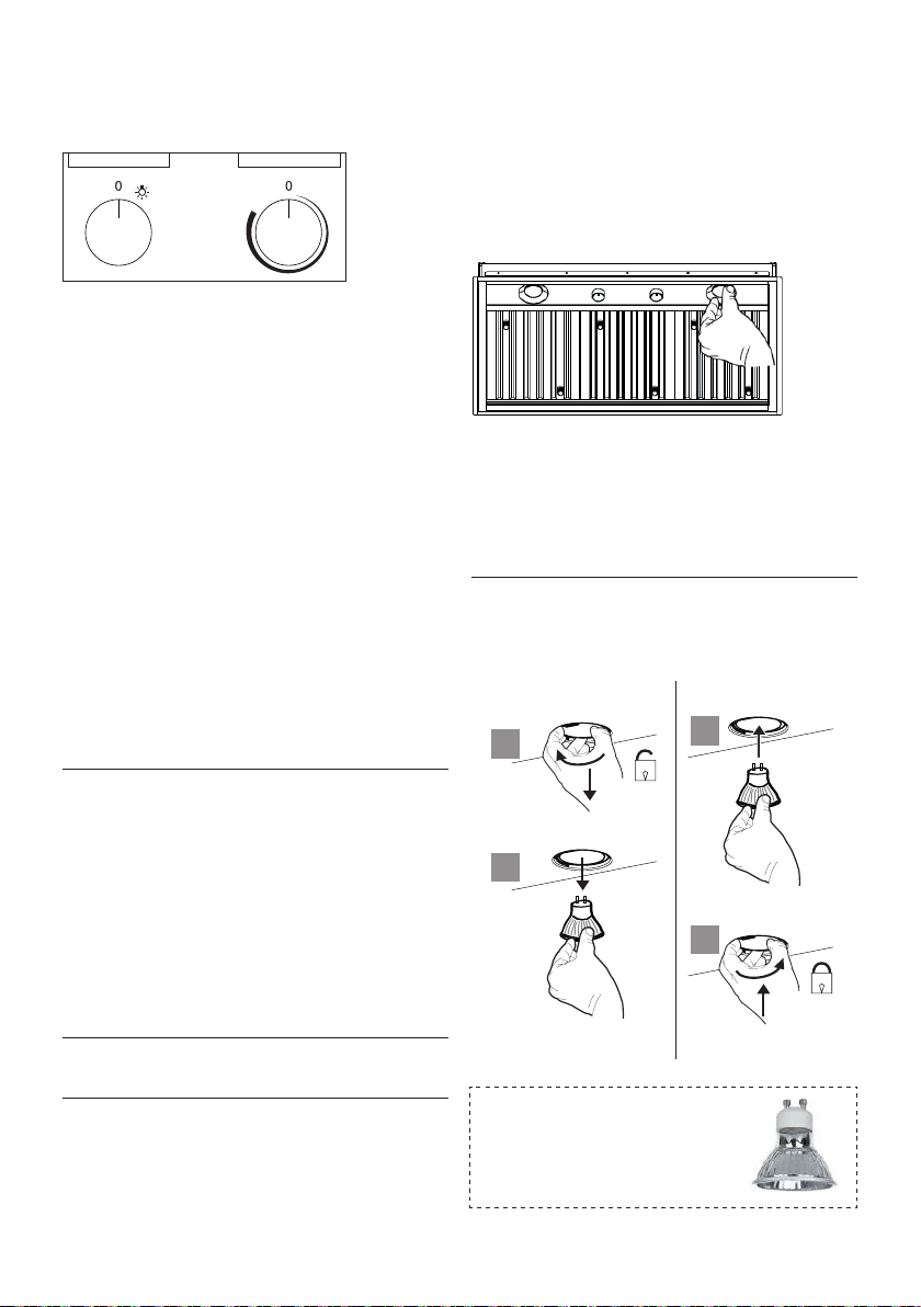
Replacing the Halogen Lamp
Before you begin, make sure that the rangehood is turned off and
that the other lamps have had sufficient time to cool. Halogen lamps
burn extremely hot and serious injury could result from touching a hot
lamp. Press and twist the lamp to remove. Then remove the lamp
and replace with a new lamp.
WIRING DIAGRAM
This rangehood uses 45 watt PAR16
Halogen Lamps.
FIGURE 27
FIGURE 26
ALL INSTALLATIONS
1. Use a drill to install side rails on the inside rangehood walls to
line the inside hood wall with stainless, 2 and 3 in FIGURE 26 with
9a. screws, 4 screws total.
BLK
WHT
R11B41
LIGHT CONTROL
OFF / HALF LIGHT / ON
1
Y-G
A
RED
WIRING BOX
WHT
BLK
BLK
23
B
ORG
WHT
4
VLT
N
L
Y-G
LINE IN
120Vac
60Hz ~
Y-G
BLU
123
654
789
123
654
987
RED
M8 4V
120V ~
WHT
BRW
BLU
BLK
ORG
BLU
BLK
Y-G
Y-G
ON/OFF MOTOR
SPEED CONTROL
BLKBLK
BLU
123
654
789
123
654
987
RED
M8 4V
120V ~
BLU
Y-G
WHT
BRW
BLKBLK
BLU
123
654
123
654
BLK
ORG
Y-G
BLU
WHT
BLK
Y-G
WIRING BOX FOR
REMOTE BLOWER
WHT
REMOTE
BLOWER
123
654
WHT
Y-G
BLKBLK
Y-G
9a
9a
2
3
9a
9a
Lampes DEL à ballast intégré
de type Gu10 – répondant à la
norme UL 1993/nmx-j-578/1-
ance/csa c22.2 No 1993
Système d'éclairage
• Remplacez l'ampoule avec une nouvelle du même
type, en vous assurant d'insérer correctement les
deux connecteurs dans leur logement sur le socle.
a
b
a
b
Installez le rail de graisse sur le dos du capot, sur
les fentes sur le plancher intérieur de l'arrière du
capot. Les ltres de graisse devraient être installé
avant d'actionner le rangehood. Pour installer les
ltres, employez les deux boutons pour tenir le
ltre et pour insérer le ltre dans le bord avant du
capot avec les boutons faisant face dehors dans la
fente à ressort. Installez l'autre extrémité du ltre
au-dessus du rail de graisse dans le dos du capot.
A B
Loading ...
Loading ...
Loading ...