Loading ...
Loading ...
Loading ...
29
5
5
4
4
9c
INSTALLATION AVEC LE VENTILATEUR À DISTANCE
(RB900 / RB1200 OU VENTILATEUR INTÉGRÉ (INLBKIT)
NOTE : SUIVEZ LES INSTRUCTIONS INCLUSES AVEC LE VENTILATEUR À DISTANCE
POUR INSTALLER LE VENTILATEUR SUR L'EXTÉRIEUR DE VOTRE MAISON.
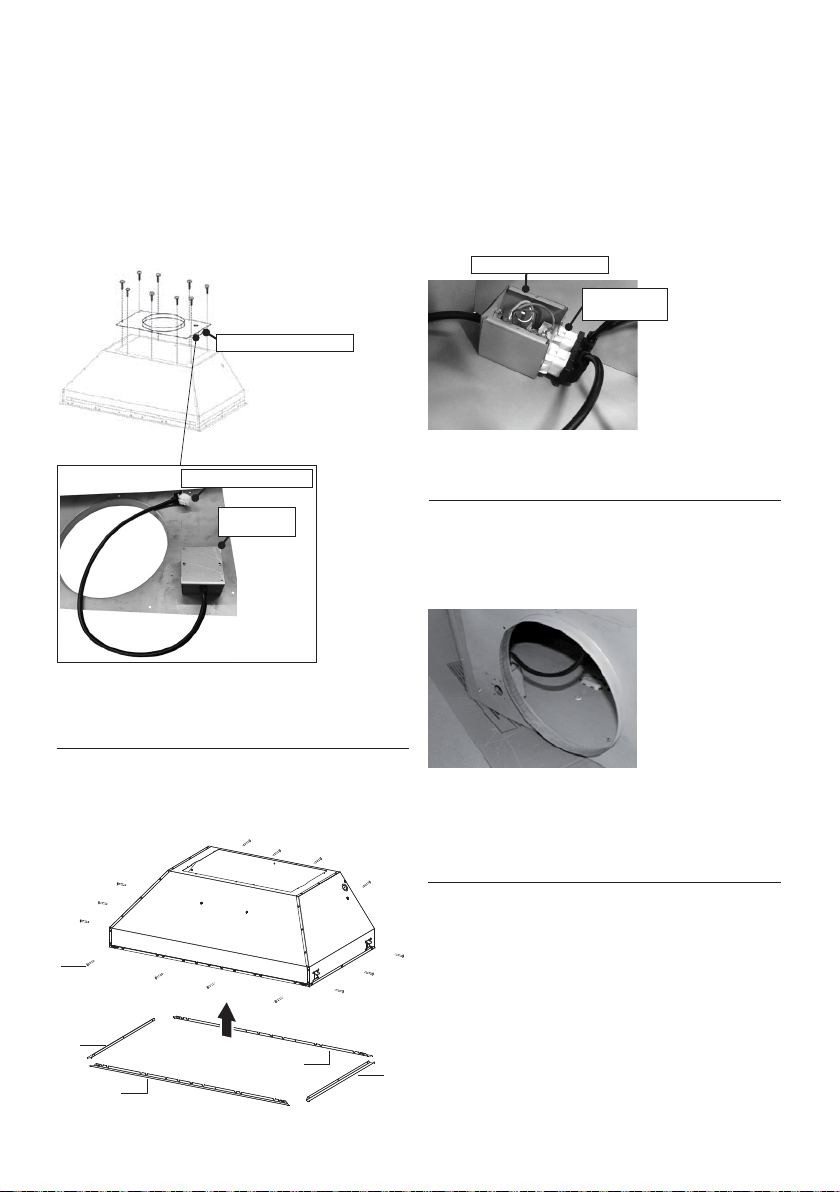
1. Installez sur le dessus de la hotte la plaque B avec
le deuxième boîtier de connexion (Figure 13) fournie
avec la trousse du ventilateur à distance. Utilisez les
9 vis fournies avec la trousse du ventilateur. Procédez
à l’ouverture de l’orice à défoncer sur le dessus de
la plaque.
2. Retirez la protection blanche de plastique et
installez les 4 pièces de garniture des côtés (4-5) sur
l’extérieur de la hotte à l’aide des 14 vis (9c). Consultez
le schéma d’installation des gouttières latérales à la
(Figure 14).
FIGURE 14
3. Branchez le câble sortant du 2e boîtier de connexion
à l’extrémité à 6 orices du 1er boîtier de connexion.
Brancher le câble sortant du boîtier noir de la carte
électronique à l’extrémité à 9 orices du 1er boîtier de
connexion (Figure 15).
Version 07/11 - Page 10
INSTALLATION WITH REMOTE BLOWER (RB900 / RB1200)
OR IN-LINE BLOWER (INLBKIT)
NOTE: FOLLOW THE INSTRUCTIONS INCLUDED WITH THE
REMOTE BLOWER TO INSTALL THE BLOWER ON THE
OUTSIDE OF YOUR HOME
.
1. Install the Plate B (FIGURE 21) which came with the remote
blower kit, on top of the rangehood. Use 9 screws supplied with
the blower kit. Remove the electrical knockout hole on top of the
plate.
2. Remove the white plastic covering and Install the 4 side trim
pieces to the outside of the hood using (16) part 9b screws, see
the side rail installation in (FIGURE 22).
FIGURE 23
FIGURE 24
4. Feed the remote blower cable thru the knockout hole in step 1
(FIGURE 24). Connect the power supply cable from the remote
blower to the wiring box on the top ducting plate of the hood. Use
step 6 on page 8 and the diagram on page 8 (FIGURE 13)
5. Attach the hood to the cabinet using (12) 9c. screws to the
cabinet. FIGURE 25
6. Follow steps 6 - 9 on page 8 to connect ducting, wiring, and
test the electrical connection. Use the wiring box connected to
the inside wall of the hood which connects to the home power
supply thru the knockout on the side of the hood.
FIGURE 21
FIGURE 22
3. Connect the wire coming out of the wiring box on the top duct
plate to the light panel 6 hole slot connector on the front inside
of the hood (FIGURE 23)
FIGURE 25
B
4. Faites passer le câble du ventilateur à distance
dans l’orice à défoncer de l’étape 1 (Figure 13, 16).
Branchez ce câble du ventilateur à distance au 2e
boîtier de connexion sur la surface inférieure de la
plaque B.
5. Suivez les étapes 4 à la page 13 pour relier la
canalisation, câblage, et examinez le raccordement
électrique. Utilisez la boîte de câblage reliée au
mur intérieur du capot qui se relie à l'alimentation
d'énergie à la maison par le coup de grâce du côté
du capot.
FIGURE 16
Version 07/11 - Page 10
INSTALLATION WITH REMOTE BLOWER (RB900 / RB1200)
OR IN-LINE BLOWER (INLBKIT)
NOTE: FOLLOW THE INSTRUCTIONS INCLUDED WITH THE
REMOTE BLOWER TO INSTALL THE BLOWER ON THE
OUTSIDE OF YOUR HOME
.
1. Install the Plate B (FIGURE 21) which came with the remote
blower kit, on top of the rangehood. Use 9 screws supplied with
the blower kit. Remove the electrical knockout hole on top of the
plate.
2. Remove the white plastic covering and Install the 4 side trim
pieces to the outside of the hood using (16) part 9b screws, see
the side rail installation in (FIGURE 22).
FIGURE 23
FIGURE 24
4. Feed the remote blower cable thru the knockout hole in step 1
(FIGURE 24). Connect the power supply cable from the remote
blower to the wiring box on the top ducting plate of the hood. Use
step 6 on page 8 and the diagram on page 8 (FIGURE 13)
5. Attach the hood to the cabinet using (12) 9c. screws to the
cabinet. FIGURE 25
6. Follow steps 6 - 9 on page 8 to connect ducting, wiring, and
test the electrical connection. Use the wiring box connected to
the inside wall of the hood which connects to the home power
supply thru the knockout on the side of the hood.
FIGURE 21
FIGURE 22
3. Connect the wire coming out of the wiring box on the top duct
plate to the light panel 6 hole slot connector on the front inside
of the hood (FIGURE 23)
FIGURE 25
B
FIGURE 13
2
e
boîtier de connexion
FIGURE 15
1
e
boîtier de connexion
2
e
boîtier de
connexion
Extrémité à 6 orices
Extrémité à 6
orices
Loading ...
Loading ...
Loading ...