Loading ...
Loading ...
Loading ...
28
INSTALLATION AVEC LE VENTILATEUR IB1200
INTERNE (cfm 1200)
1. Installez la plaque de canalisation B (Figure 7)
fournie dans la trousse du ventilateur, sur le haut
de la hotte, avec les orices à proximité de l’avant.
Utilisez les 9 vis fournies avec la trousse du ven-
tilateur.
2. Retirez la protection blanche de plastique et
installez les 4 pièces de garniture des côtés (4-5)
sur l’extérieur de la hotte à l’aide des 14 vis (9c).
Consultez le schéma d’installation des garnitures
à la (Figure 8).
3. Fixez la parenthèse de ventilateur à l’intérieur
de la hotte avec 2 vis sur le dessus de la hotte et
2 à l’arrière, le tout fourni avec la trousse du venti-
lateur (Figure 9).
5
5
4
4
9c
Version 07/11 - Page 9
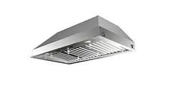
INSTALLATION WITH IB1200 INTERNAL BLOWER (1200 cfm)
1. Install the Plate B (FIGURE 14) which came with the internal
blower kit, on top of the rangehood with the holes located closer to
the front. Use 9 screws supplied with the blower kit
2. Remove the white plastic covering and Install the 4 side trim
pieces to the outside of the hood using (16) part 9b screws, see
the side rail installation in (FIGURE 15).
3. Attach the blower bracket divider inside the hood, with the 2
screws into the top of the hood and 2 screws into the back, all
supplied with the blower kit (FIGURE 16)
FIGURE 16
FIGURE 17
4. Install the 2 motor kits into the sides of the blower bracket using
the 4 screws supplied with the motor kit. (FIGURE 17)
5. Connect the wire (FIGURE 18) that comes with the motor kit
from the side of the two motors to the connection on the inside
of the light panel in the hood. The two - 9 hole ends of the wire
are installed in the two motors, the 6 hole end is connected to
the light panel (FIGURE 11 on the previous page)
FIGURE 15
FIGURE 18
FIGURE 19
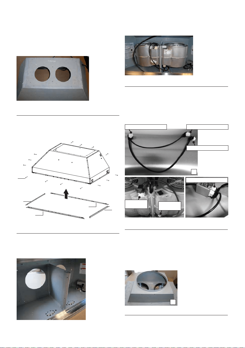
6. Install the 2 dampers on top of the hood. If you want one 10"
round duct to come out of the top of the hood, use the transition
piece (FIGURE 19) that comes with the motor kit and install with
four screws. If you want to use 2 seperate 6" round ducts, do not
use the transition.
7. Attach the hood to the cabinet using (12) 9c. screws to the
cabinet. FIGURE 20
8. Follow steps 6 - 9 on the previous page to connect ducting,
wiring, and test the electrical connection.
FIGURE 14
FIGURE 20
B
Version 07/11 - Page 9
INSTALLATION WITH IB1200 INTERNAL BLOWER (1200 cfm)
1. Install the Plate B (FIGURE 14) which came with the internal
blower kit, on top of the rangehood with the holes located closer to
the front. Use 9 screws supplied with the blower kit
2. Remove the white plastic covering and Install the 4 side trim
pieces to the outside of the hood using (16) part 9b screws, see
the side rail installation in (FIGURE 15).
3. Attach the blower bracket divider inside the hood, with the 2
screws into the top of the hood and 2 screws into the back, all
supplied with the blower kit (FIGURE 16)
FIGURE 16
FIGURE 17
4. Install the 2 motor kits into the sides of the blower bracket using
the 4 screws supplied with the motor kit. (FIGURE 17)
5. Connect the wire (FIGURE 18) that comes with the motor kit
from the side of the two motors to the connection on the inside
of the light panel in the hood. The two - 9 hole ends of the wire
are installed in the two motors, the 6 hole end is connected to
the light panel (FIGURE 11 on the previous page)
FIGURE 15
FIGURE 18
FIGURE 19
6. Install the 2 dampers on top of the hood. If you want one 10"
round duct to come out of the top of the hood, use the transition
piece (FIGURE 19) that comes with the motor kit and install with
four screws. If you want to use 2 seperate 6" round ducts, do not
use the transition.
7. Attach the hood to the cabinet using (12) 9c. screws to the
cabinet. FIGURE 20
8. Follow steps 6 - 9 on the previous page to connect ducting,
wiring, and test the electrical connection.
FIGURE 14
FIGURE 20
B
4. Installez les 2 kits de moteur sur les côtés de la
parenthèse de ventilateur utilisant les 4 vis four-
nies avec le kit de moteur (Figure 10).
7. Suivez la procédure décrite à l’étape 4 de la page
13 pour le raccord de la canalisation, les branche-
ments et l’essai de la connexion électrique.
Version 07/11 - Page 9
INSTALLATION WITH IB1200 INTERNAL BLOWER (1200 cfm)
1. Install the Plate B (FIGURE 14) which came with the internal
blower kit, on top of the rangehood with the holes located closer to
the front. Use 9 screws supplied with the blower kit
2. Remove the white plastic covering and Install the 4 side trim
pieces to the outside of the hood using (16) part 9b screws, see
the side rail installation in (FIGURE 15).
3. Attach the blower bracket divider inside the hood, with the 2
screws into the top of the hood and 2 screws into the back, all
supplied with the blower kit (FIGURE 16)
FIGURE 16
FIGURE 17
4. Install the 2 motor kits into the sides of the blower bracket using
the 4 screws supplied with the motor kit. (FIGURE 17)
5. Connect the wire (FIGURE 18) that comes with the motor kit
from the side of the two motors to the connection on the inside
of the light panel in the hood. The two - 9 hole ends of the wire
are installed in the two motors, the 6 hole end is connected to
the light panel (FIGURE 11 on the previous page)
FIGURE 15
FIGURE 18
FIGURE 19
6. Install the 2 dampers on top of the hood. If you want one 10"
round duct to come out of the top of the hood, use the transition
piece (FIGURE 19) that comes with the motor kit and install with
four screws. If you want to use 2 seperate 6" round ducts, do not
use the transition.
7. Attach the hood to the cabinet using (12) 9c. screws to the
cabinet. FIGURE 20
8. Follow steps 6 - 9 on the previous page to connect ducting,
wiring, and test the electrical connection.
FIGURE 14
FIGURE 20
B
FIGURE 7
FIGURE 8
FIGURE 9
FIGURE 10
5. Branchez le câble de branchement D (qui se
trouve à l’intérieur de la trousse du ventilateur
interne 1 200 PCM PRO, n° d'article IB1200).
Branchez l’extrémité à 6 orices (A) au boîtier
de connexion et l’extrémité à 9 orices (B-C) aux
deux moteurs (Figure 11).
FIGURE 11
D
6. Installez les 2 registres (A) sur le dessus de la
hotte (à l’intérieur de la trousse du ventilateur interne
1 200 PCM PRO, n° d'article IB1200). Autrement,
installez le passage de la canalisation de 10" (E) (qui
se trouve à l’intérieur de la trousse du ventilateur in-
terne 1 200 PCM PRO, n° d'article IB1200) et instal-
lez-le à l’aide de quatre vis (Figure 12).
Version 07/11 - Page 9
INSTALLATION WITH IB1200 INTERNAL BLOWER (1200 cfm)
1. Install the Plate B (FIGURE 14) which came with the internal
blower kit, on top of the rangehood with the holes located closer to
the front. Use 9 screws supplied with the blower kit
2. Remove the white plastic covering and Install the 4 side trim
pieces to the outside of the hood using (16) part 9b screws, see
the side rail installation in (FIGURE 15).
3. Attach the blower bracket divider inside the hood, with the 2
screws into the top of the hood and 2 screws into the back, all
supplied with the blower kit (FIGURE 16)
FIGURE 16
FIGURE 17
4. Install the 2 motor kits into the sides of the blower bracket using
the 4 screws supplied with the motor kit. (FIGURE 17)
5. Connect the wire (FIGURE 18) that comes with the motor kit
from the side of the two motors to the connection on the inside
of the light panel in the hood. The two - 9 hole ends of the wire
are installed in the two motors, the 6 hole end is connected to
the light panel (FIGURE 11 on the previous page)
FIGURE 15
FIGURE 18
FIGURE 19
6. Install the 2 dampers on top of the hood. If you want one 10"
round duct to come out of the top of the hood, use the transition
piece (FIGURE 19) that comes with the motor kit and install with
four screws. If you want to use 2 seperate 6" round ducts, do not
use the transition.
7. Attach the hood to the cabinet using (12) 9c. screws to the
cabinet. FIGURE 20
8. Follow steps 6 - 9 on the previous page to connect ducting,
wiring, and test the electrical connection.
FIGURE 14
FIGURE 20
B
FIGURE 12
E
B) Extrémité à 9 orices
B) Extrémité
à 9 orices
C) Extrémité
à 9 orices
C) Extrémité à 9 orices
A) Extrémité à 6 orices
A) Extrémité à 6 orices
Loading ...
Loading ...
Loading ...