Loading ...
Loading ...
Loading ...
20
ENGLISH
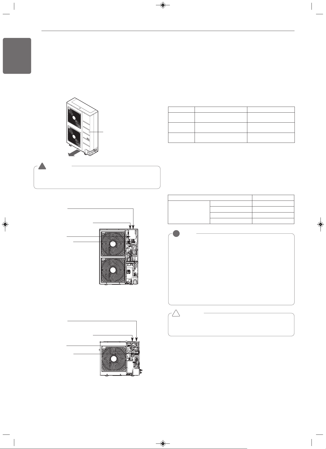
Side panel
WARNING
The temperature sensor for outdoor air should not be exposed to
direct sunlight.
- Provide an appropriate cover to intercept direct sunlight.
!
※Pictures may differ depending on the model.
※Pictures may differ depending on the model.
3, 4, 4.4, 5 Ton
Indoor communication PCB
Main PCB
Terminal block
(Take care of the phase
sequence of 1-phase
2-wire power system)
PI485 PCB
(Inside the control box)
(Inside the control box)
2 Ton
Indoor communication PCB
Main PCB
Terminal block
(Take care of the phase
Sequence of 1-phase
2-wire power system)
PI485 PCB
(Inside the control box)
(Inside the control box)
NOTE
!
• The figures are based on assumed length of parallel cabling up
to 100m(328ft). For length in excess of 100m(328ft) the figures
will have to be recalculated in direct proportion to the additional
length of cable involved.
• If the power supply waveform continues to exhibit some distor-
tion the recommended spacing in the table should be increased.
- If the cable are laid inside conduits then the following point
must also be taken into account when grouping various cable
together for introduction into the conduits
- Power cable(including power supply to air conditioner) and
communication cables must not be laid inside the same
- In the same way, when grouping the power wires and com-
munication cables should not be bunched together.
Current capacity of power cable Spacing
100V or more
10A 300m(11-13/16 inch)
50A 500m(19-11/16 inch)
100A 1,000m(39-3/8 inch)
Exceed 100A 1,500m(59-1/16 inch)
CAUTION
If apparatus is not properly earthed then there is always a risk of
electric shocks, the earthing of the apparatus must be carried out by
a qualified person.
!
Wiring of main power supply and equipment
capacity
- Use a separate power supply for the Outdoor Unit and Indoor Unit.
- Bear in mind ambient conditions (ambient temperature,direct sun-
light, rain water,etc.) when proceeding with the wiring and connec-
tions.
- The cable size is the minimum value for metal conduit wiring. The
power cord size should be 1 rank thicker taking into account the line
voltage drops. Make sure the power-supply voltage does not drop
more than 10%.
- Specific wiring requirements should adhere to the wiring regulations
of the region.
Communication and Power Cables
Communication cable
- Types : shielding cable
- Cross section : 1.0~1.5mm
2
(1.55x10
-3
~2.32x10
-3
in
2
)
- Maximum allowable temperature: 140°F
- Maximum allowable cable length: under 1,000m(3,281ft)
Remote control cable
- Types : 3-core cable
Central control cable
Separation of communication and power cables
- If communication and power cables are run alongside each other then
there is a strong likelihood of operational faults developing due to in-
terference in the signal wiring caused by electrostatic and electro-
magnetic coupling.
The tables below indicates our recommendation as to appropriate
spacing of communication and power cables where these are to be
run side by side
Product type Cable type Diameter
ACP
2-core cable
(Shielding cable)
1.0~1.5mm
2
(1.55x10
-3
~2.32x10
-3
in
2
)
AC Smart
2-core cable
(Shielding cable)
1.0~1.5mm
2
(1.55x10
-3
~2.32x10
-3
in
2
)
AC Ez
4-core cable
(Shielding cable)
1.0~1.5mm
2
(1.55x10
-3
~2.32x10
-3
in
2
)
Control box and connecting position of wiring
- Remove all of the screws at side panel and remove the panel by
pulling it forward.
- Connect communication cables between outdoor unit and indoor
units through the terminal block.
- When the central control system is connected to the outdoor unit, a
dedicated PCB must be connected between them.
- When connecting communication cable between outdoor unit and in-
door units with shielded cable, connect the shield ground to the earth
screw.
1,MFL67798024,영영 18. 7. 19. 영영 2:14 Page 20
Loading ...
Loading ...
Loading ...