
BERTAZZONI
INSTALLATION MANUAL
FREESTANDING ELECTRIC RANGES
3100295
WWW.BERTAZZONI.COM

2
/ Table of contents
TABLE OF CONTENTS
WARNINGS ___________________________________________________________________
DATA RATING LABEL ___________________________________________________________
BEFORE INSTALLATION ________________________________________________________
VENTILATION PREPARATION ____________________________________________________
SPECIFICATIONS ______________________________________________________________
CLEARENCE DIMENSIONS ______________________________________________________
INSTALLATION REQUIREMENTS _________________________________________________
Electrical ___________________________________________________________________
ELECTRICAL CONNECTION ____________________________________________________
WIRING DIAGRAM _____________________________________________________________
INSTALLATION ________________________________________________________________
Unpackaging the range ________________________________________________________
Removing the oven door _______________________________________________________
Installing the legs _____________________________________________________________
Installing the worktop frontguard ________________________________________________
Installing the island trim _______________________________________________________
Installing backguard (optional) __________________________________________________
INSTALLING THE ANTI-TIP DEVICES ______________________________________________
Anti-tip brackets ______________________________________________________________
Anti-tilt chain ________________________________________________________________
INSTALLATION CHECKLIST ______________________________________________________
FINAL PREPARATION ___________________________________________________________
BERTAZZONI SERVICE _________________________________________________________
4
5
6
7
7
8
9
9
10
11
13
13
13
14
14
15
15
16
16
16
17
17
18

3
/ Models
Models
MAST365INMXE
MAST365INSXT
Models
PROF304INMXE
PROF304INMXT
PROF304INSART
PROF304INSBIT
PROF304INSGIT
PROF304INSNET
PROF304INSROT
PROF304INSXT
PROF365INSART
PROF365INSBIT
PROF365INSGIT
PROF365INSNET
PROF365INSROT
PROF365INSXT
4
/ Warnings
WARNINGS
To ensure proper and safe operation, the applian-
ce must be properly installed and grounded by a
qualifi ed technician. DO NOT attempt to adjust,
repair, service, or replace any part of your applian-
ce unless it is specifi cally recommended in this
manual. All other servicing should be referred to
a qualifi ed servicer.
FOR THE INSTALLER: Before installing the Ber-
tazzoni appliance, please read these instructions
carefully. This appliance shall be installed in ac-
cordance with the manufacturer’s installation in-
structions. Leave these instructions with the ow-
ner, who should save them for local inspector’s
use and for future reference. DO NOT remove
permanently affi xed labels, warnings, or plates
from product. This may void the warranty.
Installation must conform with all local codes.
This range is NOT designed for installation in ma-
nufactured (mobile) homes or recreational park
trailers.
DO NOT install this range outdoors.
This appliance must be properly grounded.
Grounding reduces the risk of electric shock by
providing a safe pathway for electric current in the
event of a short circuit.
Warning!
To avoid risk of property damage, personal
injury or death; follow information in this ma-
nual exactly to prevent a fi re or explosion.
Warning!
To avoid risk of property damage, personal injury
or death; follow information in this manual exact-
ly to prevent a fi re or explosion. DO NOT store
or use gasoline or other fl ammable vapors and
liquids nearbythis or any appliance.
NOTE: Installation and service must be perfor-
med by a qualifi ed installer, service agency or the
gas supplier.
DANGER!!! ELECTRIC SHOCK HAZARD!!!
To avoid risk of electrical shock, personal injury
or death, verify that the appliance has been pro-
perly grounded in accordance with local codes or
in absence of codes, with the National Electrical
Code (NEC). ANSI/NFPA 70- latest edition.
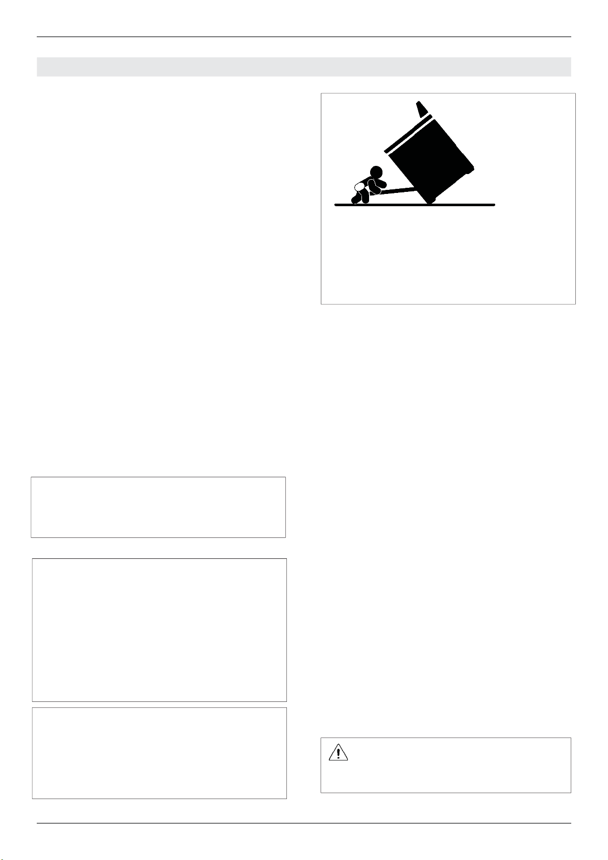
Warning - tipping hazard
Children and adults can tip over the range if it has
not been secured.This may lead to fatal injuries.
To reduce the risk of the appliance tipping, it must
be secured and connected using the anti-tip devi-
ce according to the installation instructions.
Re-engage the anti-tip device if the range is
moved. Do not operate the range without te
anti-tipdevice in place and engaged. Do not
use the range if the anti-tip device has not been
properly installed and engaged. See installation
instructions for details.
Failure to observe the information con-
tained in the installation instructions can
lead to serious or fatal injuries for chil-
dren and adults.
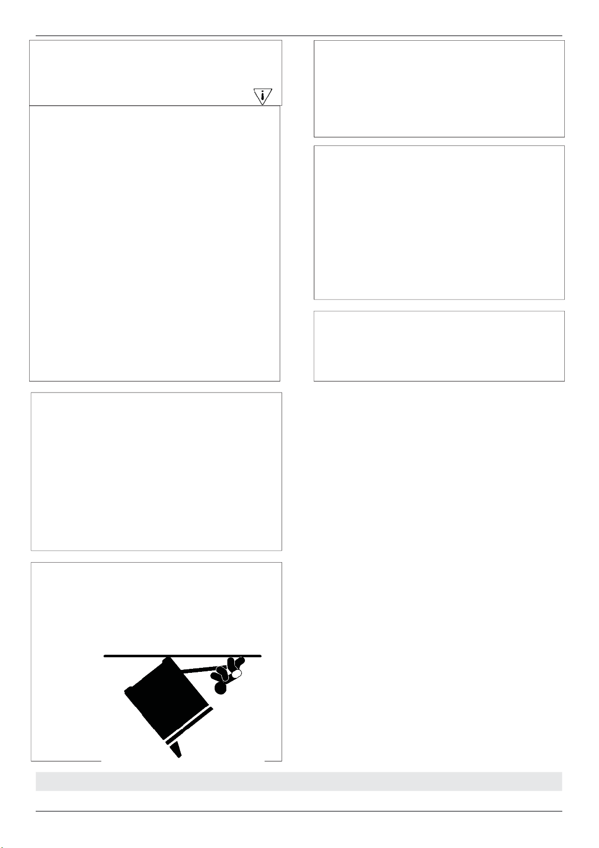
DO NOT lift the range by the oven door’s handle,
as this may damage the door hinges and cause
the door to fi t incorrectly.
DO NOT lift the appliance by the range’s control
panel.
The unit is heavy and should be handled accor-
dingly. Proper safety equipment such as gloves
and adequate manpower of at least two people
must be used in moving the range to avoid injury
and to avoid damage to the unit or the fl oor.
Rings, watches, and any other loose items that
may damage the unit or otherwise might become
entangled with the unit should be removed.
Hidden surfaces may have sharp edges. Use cau-
tion when reaching behind or under appliance.
DO NOT use a hand truck or appliance dolly on
the back or front of the unit. Handle from the side
only.
WARNING:
Cancer and Reproductiv Harm-
www.P65Warnings.ca.gov
.

5
/Data rating label
DATA RATING LABEL
The data rating label shows the model and serial
number of the range. It is located under the con-
trol panel and in the last page of this manual

6
/ Before installation
• This appliance shall only be installed by an au-
thorized professional.
• This appliance shall be installed in accordance
with the manufacturer’s installation instructions.
• This appliance must be installed in accordance
with the norms & standards of the country whe-
re it will be installed.
• The appliance, when installed, must be electri-
cally grounded in accordance with local codes
or, in the absence of local codes, with the Natio-
nal Electrical Code, ANSI/NFPA 70.
All opening and holes in the wall and fl oor, back
and under the appliance shall be sealed before
installation of the appliance.
Room ventilation
An exhaust fan may be used with the appliance;
in each case it shall be installed in conformity
with the appropriate national and local standards.
Exhaust hood operation may aff ect other vented
appliances; in each case it shall be installed in
conformity with the appropriate national and local
standards.
Warning
This appliance should not be installed with a
ventilation system that directs air in a downward
direction toward the range. This type of ventila-
tion system may cause ignition and combustion
problems with the appliance resulting in personal
injury, property damage, or unintended operation.
Ventilating systems that direct the air upwards do
not have any restriction.
Do not use aerosol sprays in the vicinity of
this appliance while it is in operation.
BEFORE INSTALLATION
7
This range will best perform when installed with
Bertazzoni exhaust hoods. These hoods have
been designed to work in conjunction with the
Bertazzoni range and have the same fi nish for a
perfect look.
Before installation of the exhaust hood, consult lo-
cal or regional building and installation codes for
additional specifi c clearance requirements.
Refer to the range hood installation instructions
provided by the manufacturer for additional infor-
mation.
Select Hood and Blower Models:
• For wall installations, the hood should be equal
or larger width than the range. Where space
permits, a hood larger than the range may be
desirable for improved ventilation performance.
• For island installations, the hood width should
overhang the range by a minimum of 3” (76
mm) on each side.
Hood Placement:
• For best removal of smoke and odors, the
lower edge of the hood should be installed
between 25 1/2” (65 cm) and 31 1/2” (80 cm)
above the range cooking surface.
• If the hood contains any combustible materials
(i.e. a wood covering), it must be installed at a
minimum of 36” (914 mm) above the cooking
surface.
Consider Make-Up Air:
Due to the high volume of ventilation air, a sour-
ce of outside replacement air is recommended.
This is particularly important for tightly sealed
and insulated homes. A qualifi ed heating and
ventilating contractor should be consulted.
/ Ventilation preparation / Specifi cations
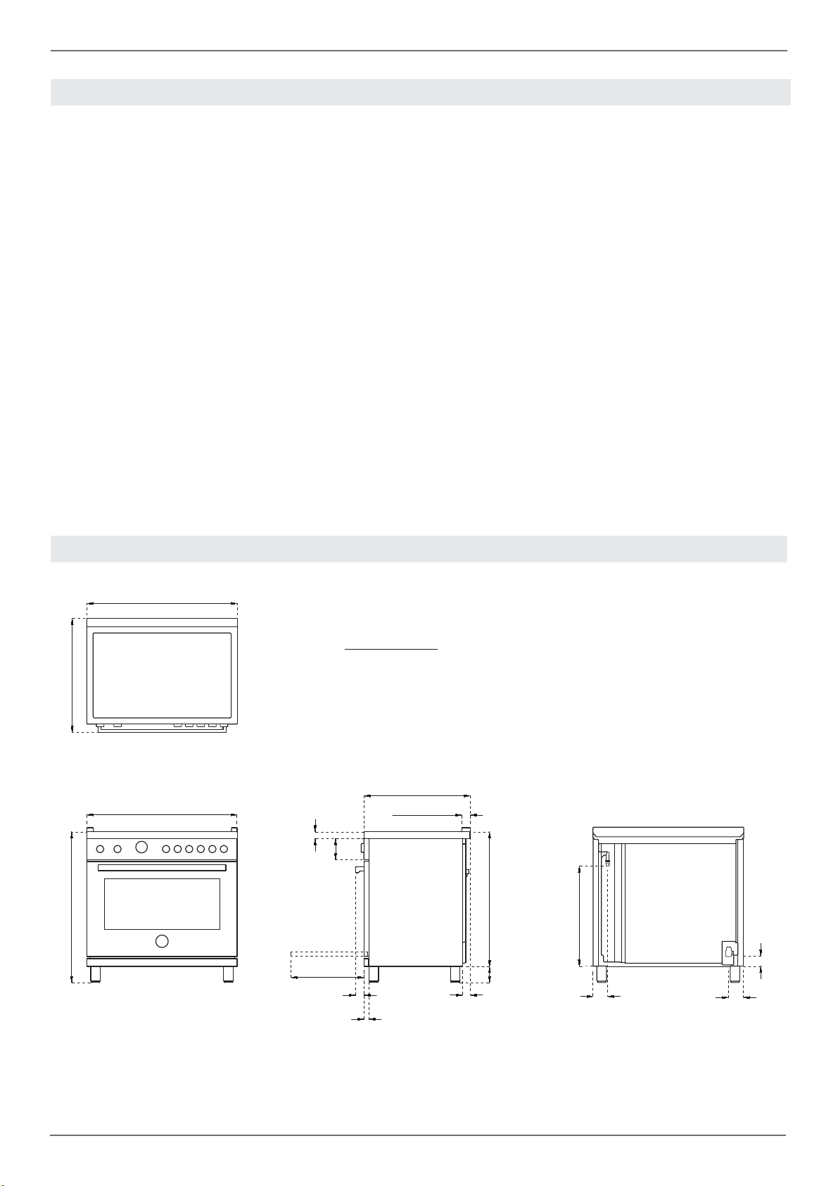
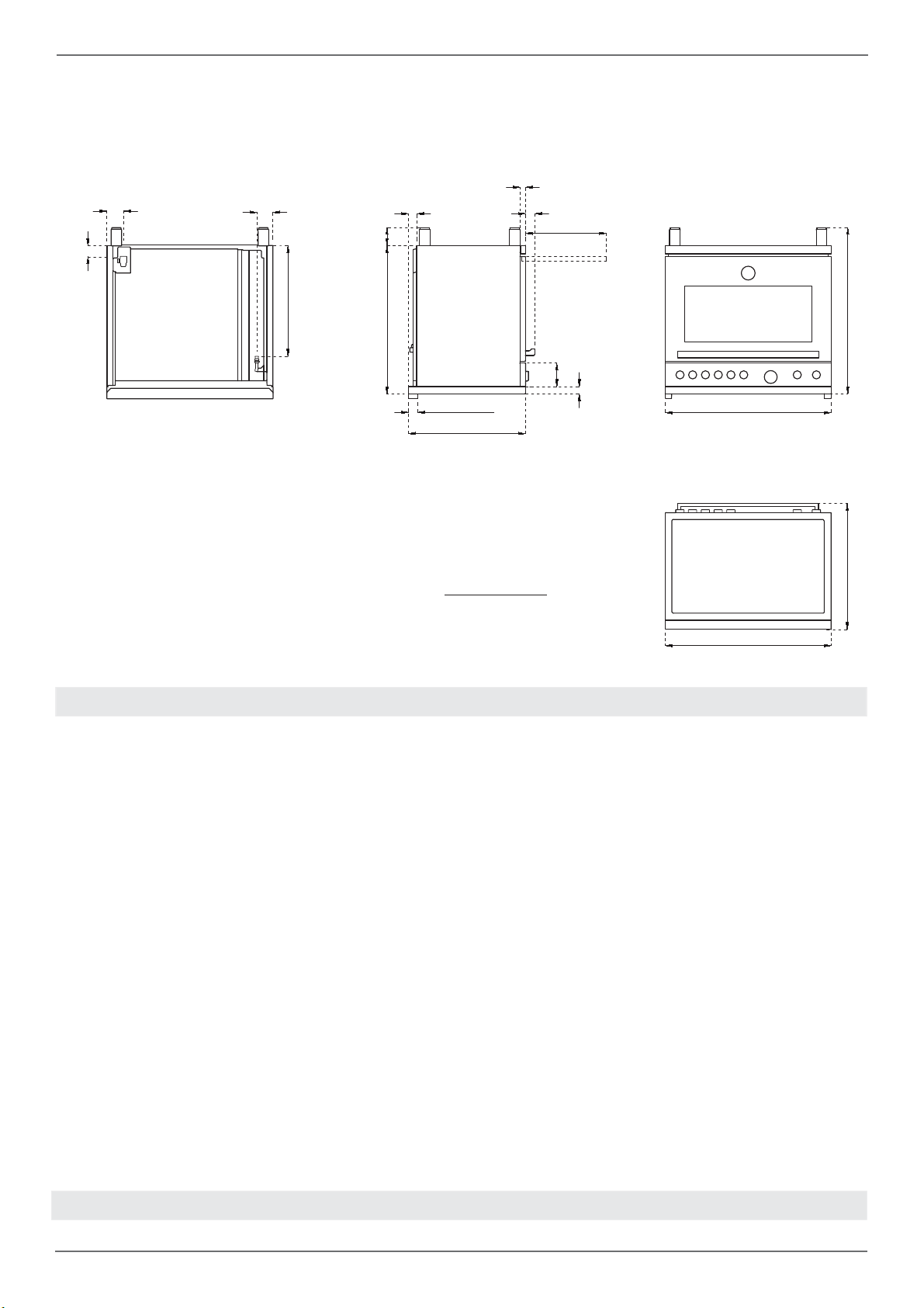
VENTILATION PREPARATION
SPECIFICATIONS
A
27''
/8
37''
1/2
MAX
1''
15/16
25''
/16
2''
1''
5/8
32''
3''
3/4
- 5''
1/2
5''
1''
5/8
1''
1/8
''
/
23''
7/8
3''
7/16
3 ''
11/16
2''
7/16
A
A
30’’ 36’’ 48’’
8
/ Clearence dimensions
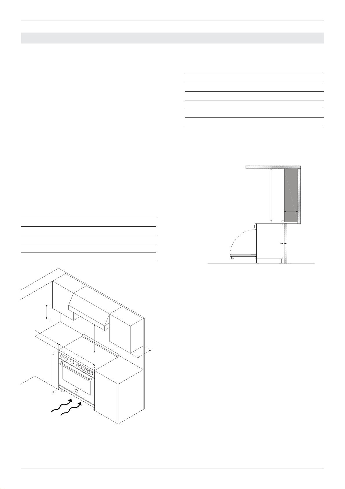
CLEARENCE DIMENSIONS
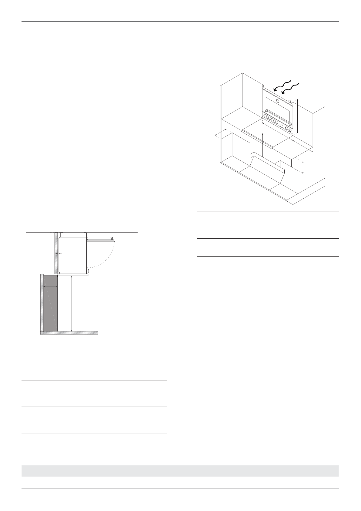
Installation adjacent to kitchen cabinets
This range may be installed directly adjacent to
existing countertop high cabinets (36” or 91.5 cm
from the fl oor).
For the best look, the worktop should be level with
the cabinet countertop. This can be accomplished
by raising the unit using the adjustment spindles
on the legs.
ATTENTION: the range CANNOT be installed di-
rectly adjacent to kitchen walls, tall cabinets, tall
appliances, or other vertical surfaces above 36”
(91.4 cm) high. The minimum side clearance in
such cases is 6” (15.2 cm).
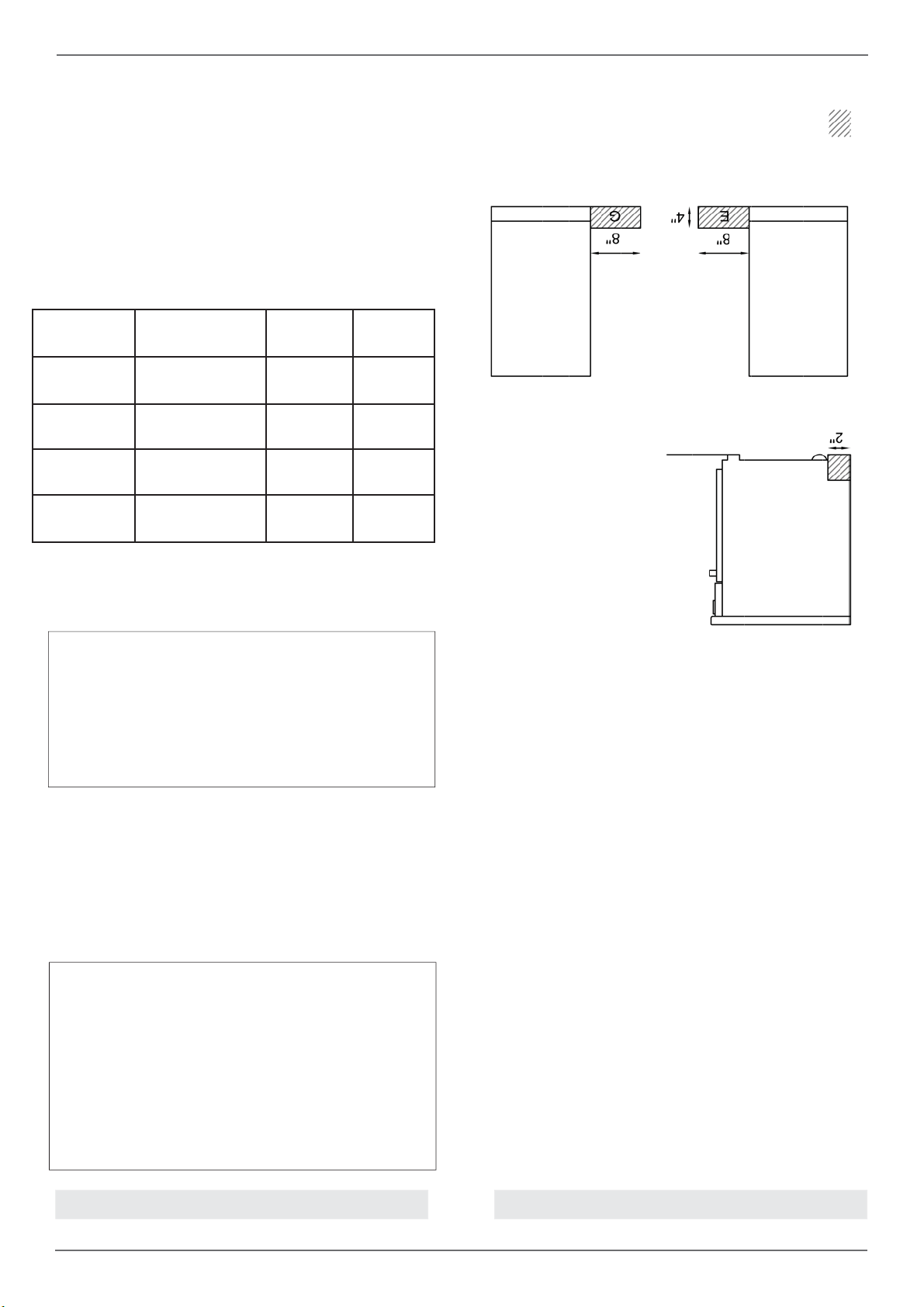
Wall cabinets with minimum side clearance must
be installed 18” (45.7 cm) above the countertop
with countertop height between 35 ½” (90.2 cm)
and 37 ¼” (94.6 cm). The maximum depth of wall
cabinets above the range shall be 13” (33.0 cm).
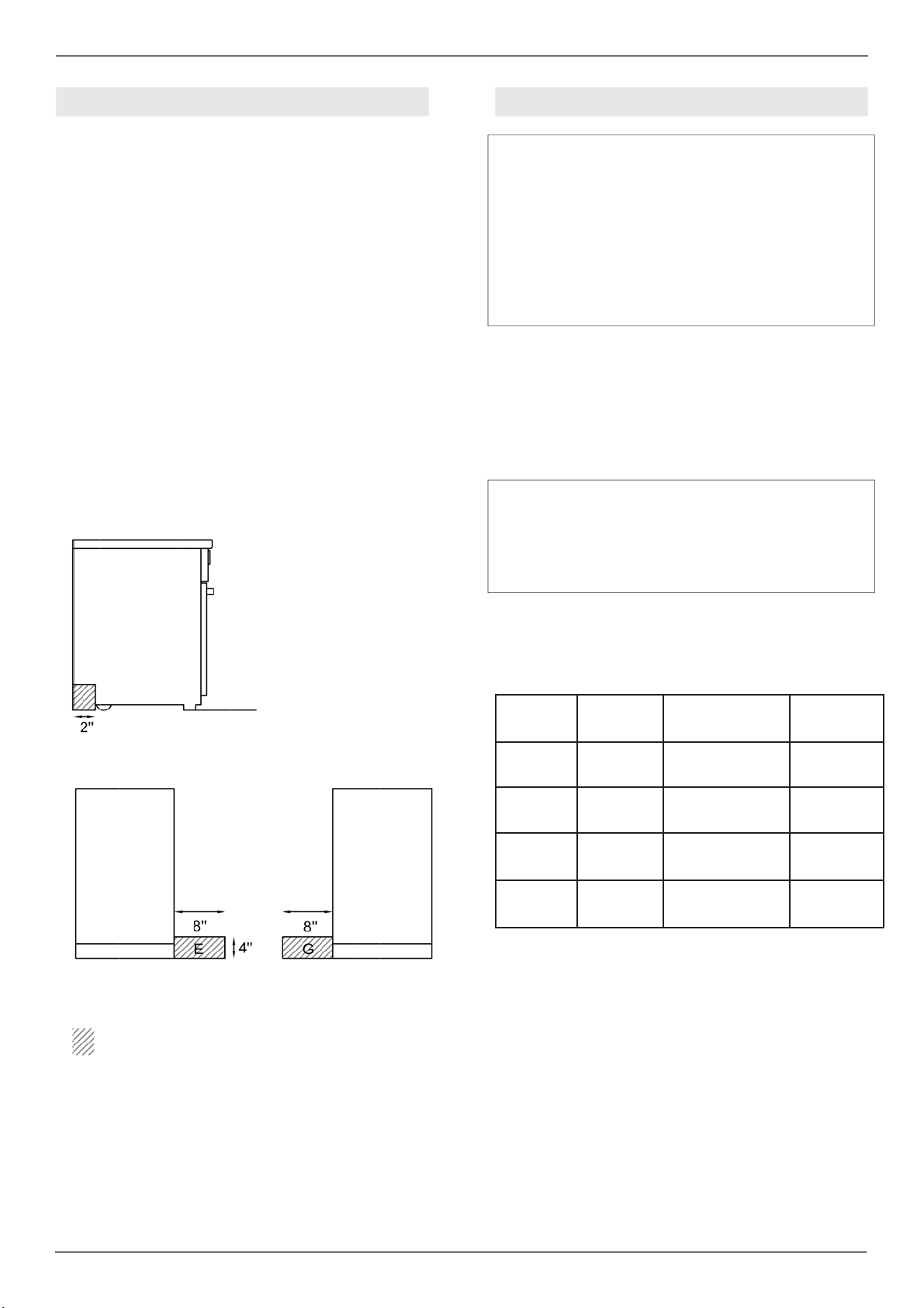
Cabinet
If installing toekick, verify that the sum of the cu-
tout areas equal the recommended ventilation (L)
30” area 40 sq. inches ( 25840 mm2)
36” area 51 ½ sq. inches ( 33107 mm2)
48” area 73 ½ sq.inches ( 47547 mm2)
Shaded area behind range indicates minimum
clearance to combustible surfaces, combustible
materials cannot be located within this area.
12” (305 mm) min. to combustible surface with
Flush Island Trim
For Flush Island installations, counter surface
should have a cantilever edge meeting the back
section of the Flush Island Trim accessory.
Metal hood
A
B
C
D
E
F
A
B
C
D
E
F
G
H
30’’ (76,2 cm)
36’’ (91,5 cm) hood with combustible materials
13’’ (33,0 cm)
18’’ (45,7 cm)
35’’ 1/2(90,2 cm) / 37”
1/4
(94,6 cm)
6’ (15,2 cm)
30’’ (76,2 cm)
25 1/2’’(65 cm) and 31 1/2’’ (80 cm)
13’’ (33,0 cm)
18’’ (45,7 cm)
35’’ 1/2(90,2 cm) / 37”
1/4
(94,6 cm)
6’ (15,2 cm)
12”(30,50 cm)
1” 9/16(4 cm)
A
F
D
B
C
E
/
B
G
H
9
/ Installation requirements / Electrical connection
ELECTRICAL
A properly-grounded horizontally- mounted electri-
cal receptacle should be installed no higher than
3” (7.6 cm) above the fl oor, no less than 2” (5 cm)
and no more than 8” (20,3 cm) from the left side
(facing product).
Check all local code requirements.
.
Warning!
ELECTRICAL SHOCK HAZARD
Disconnect electrical power at the circuit bre-
aker box or fuse box before installing the ap-
pliance.
Provide appropriate ground for the appliance.
Use copper conductors only.
Failure to follow these instructions could re-
sult in serious injury or death.
Electrical grounding
This appliance is equipped with a three-prong
plug for your protection against shock hazard and
should be plugged directly into a properly groun-
ded socket. Do not cut or remove the grounding
prong from this plug.
Caution
Label all wires prior to disconnecting when
servicing controls. Wiring errors can cause
improper and dangerous operation.
Verify proper operation after servicing.
The appliance shall be connected to a single pha-
se electric line rated at 120/208Vac or 120/240Vac
and 60Hz frequency.
Install a suitable electric power supply receptacle
connection type NEMA 14-50R able to support a
load of at least 30 A (per line) according to local
code requirements. For four or three wires power
supply connection system see diagram below.
INSTALLATION REQUIREMENTS ELECTRICAL CONNECTION
installation area for the connection
Type Voltage Circuit rating Electrical
supply
30” IND-
DFM
120/208V
120/240V
10300W 46A
11000W 48A
40A
40A
30” IND-
DFS
120/208V
120/240V
11700W 53A
13000W 56A
40A
40A
36” IND-
DFM
120/208V
120/240V
14000W 62A
14800W 64A
40A
40A
36” IND-
DFS
120/208V
120/240V
15600W 70,5A
17000W 73,5A
50A
50A
10
/ Electrical connection
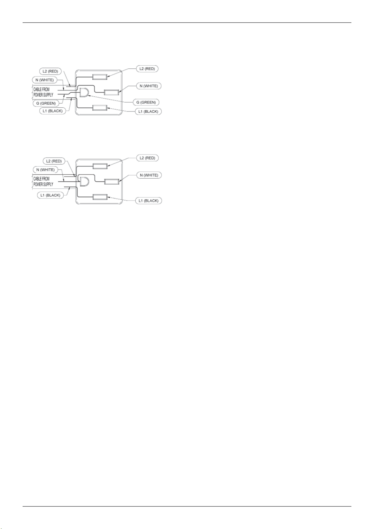
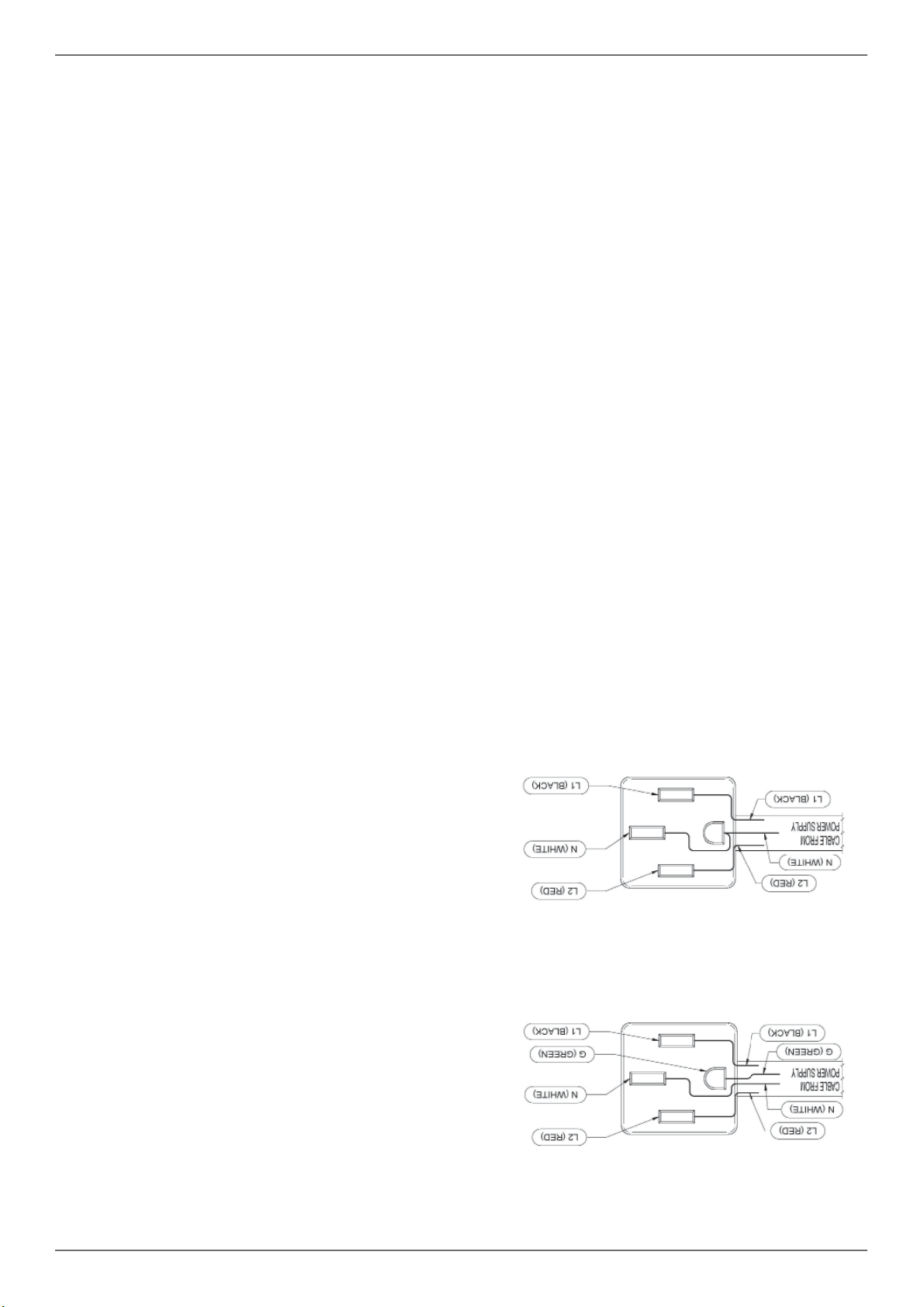
FOUR-WIRE CONN.RECEPTACLE NEMA 14-50R
THREE-WIRE CONN.RECEPTACLE NEMA 14-50R
Check your local code for which of the options be-
low should be used in grounding the receptacle
power supply connections.
OPTION 1 – FOUR Wires connection:
-Connect the L1 receptacle terminal to the inco-
ming BLACK electrical supply wire (L1-hot wire)
-Connect the L2 receptacle terminal to the inco-
ming RED electrical supply wire (L2-hot wire)
-Connect the NEUTRAL receptacle terminal to
the incoming NEUTRAL (WHITE) electrical sup-
ply wire
-Connect the GROUND receptacle terminal to the
incoming GROUND (GREEN) electrical supply
wire
OPTION 2 - THREE-Wires connection:
-Connect the L1 receptacle terminal to the inco-
ming BLACK electrical supply wire (L1-hot wire)
-Connect the L2 receptacle terminal to the inco-
ming RED electrical supply wire (L2-hot wire)
-Connect the NEUTRAL with the GROUND recep-
tacle terminal to the incoming NEUTRAL (WHITE)
electrical supply wire
DO NOT USE EXTENSION CORDS WITH
THIS APPLIANCE AS IT MAY RESULT IN FIRE,
ELECTRIC SHOCK OR OTHER type of PERSO-
NAL INJURY.
The appliance is equipped at the factory with
an electric supply cord set 4 wires type with ring
terminals (L1, L2, N, Ground) suitable for range
use UL/CSA listed type SRDT/DRT 2x6AWG (L1,
L2)+2x8AWG (N, G) rated 300V, 40 or 50A with
fused plug type NEMA 14-50P; cable length 1,5
m.; in case the supply cord set must be replaced,
it shall be replaced with an identical set having the
same technical specs and following carefully the
instructions and diagrams below:
11
/ Wiring diagram
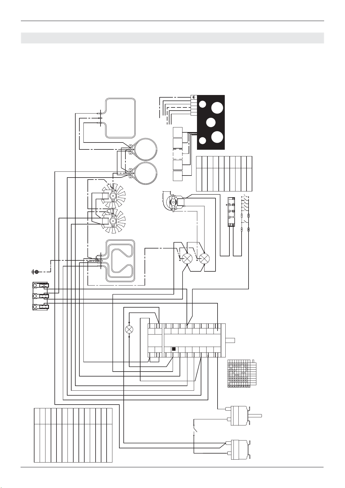
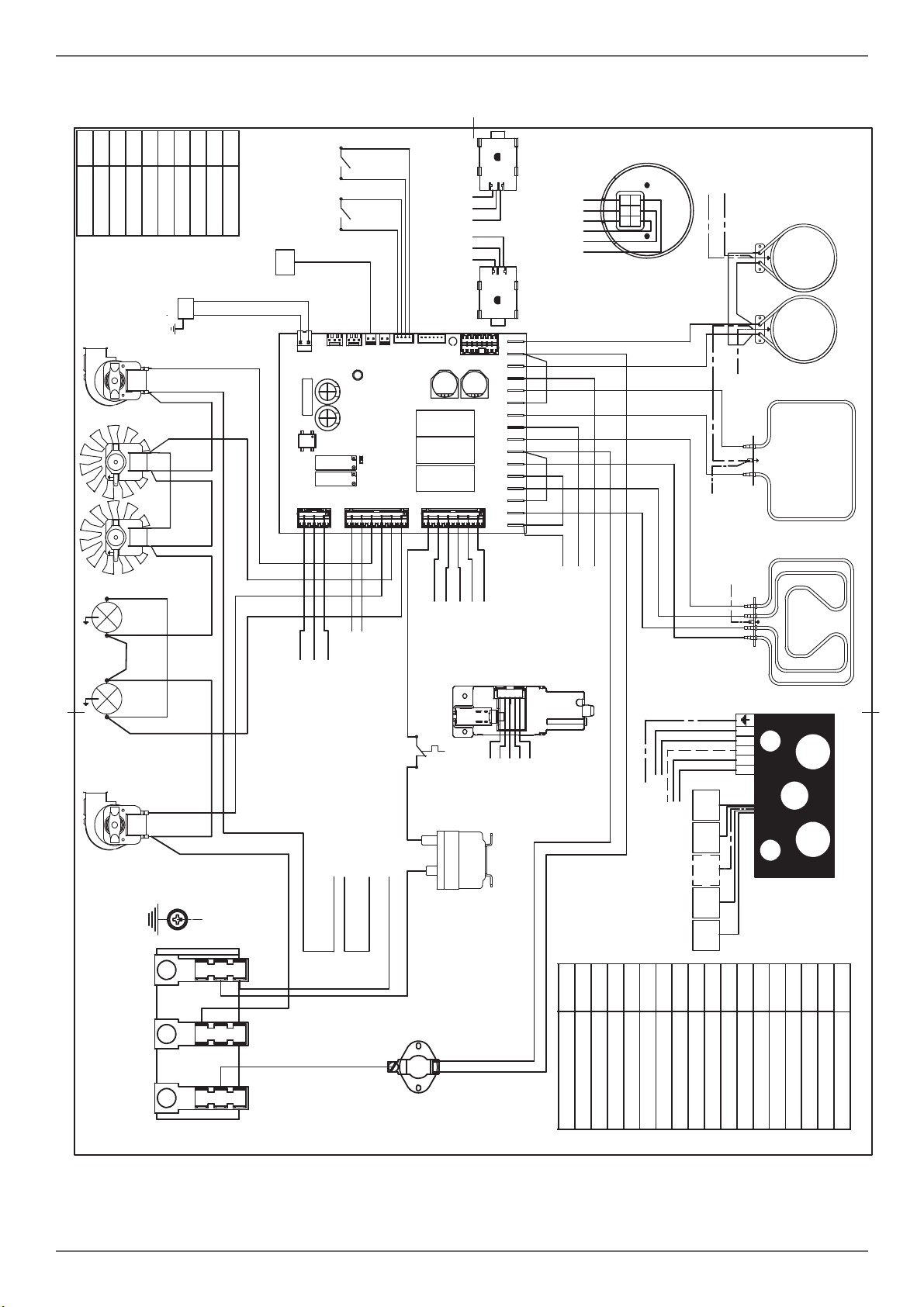
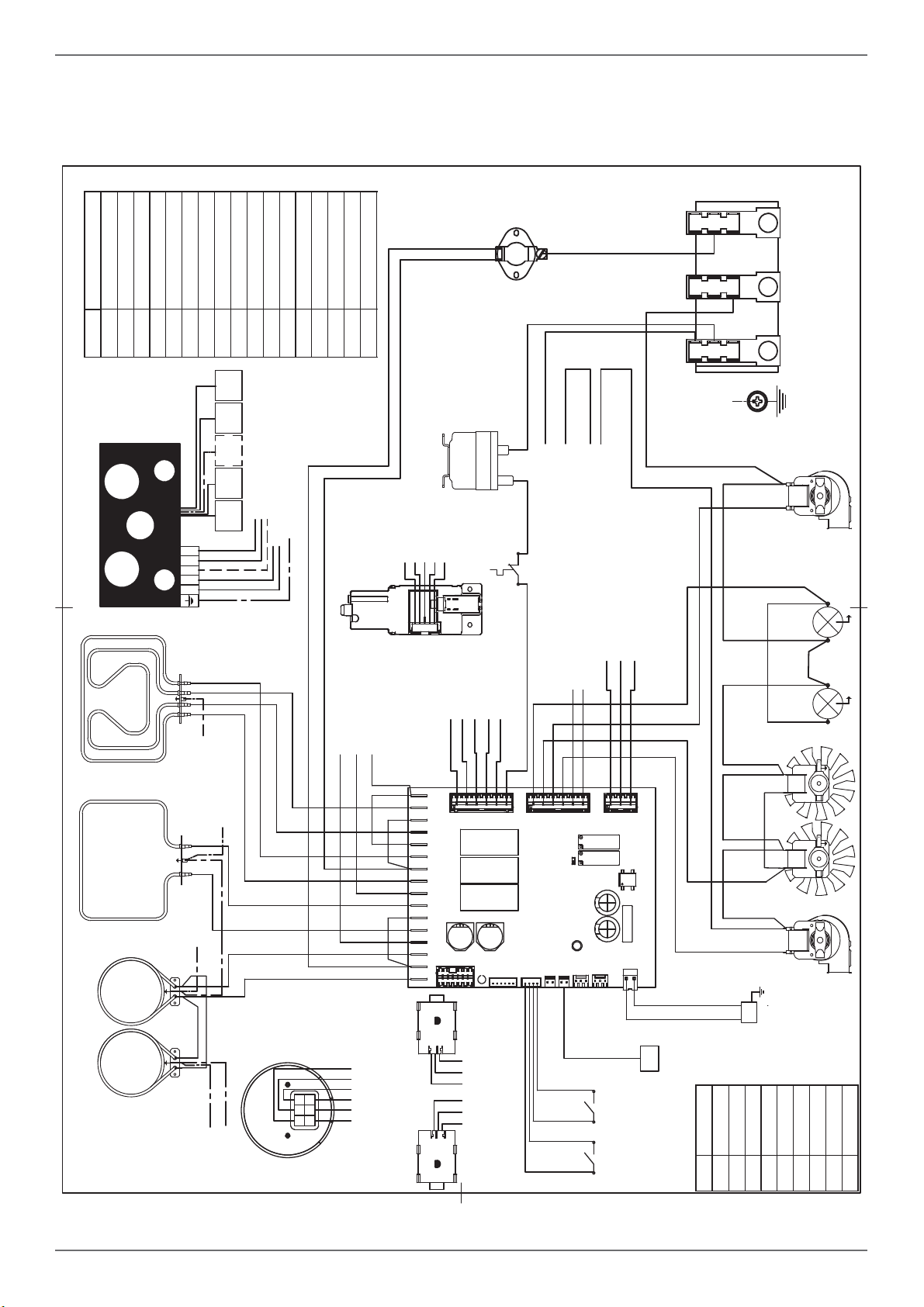
WIRING DIAGRAM
The electric wiring diagrams and schematics are attached behind the range, and should not be removed
except by a service technician, then replaced after service.
DFM
G
IGN
bi
S
LF
MVT
T
RG+RC
RP
n
a
b
b
M
L1 N L2
GROUND
TSS
1
2
CMV
P1
Commutatore.9+0
1
P2
P3
P4
P5
P6
P7
P8
P1
P2
2
3
4
5
6
7
8
1
2
P2
P1
P8
P7
P6
P5
P4
P3
P2
1
0
4
3
P1
2
5
6
7
8
9
COM
RCRC
MV MV
LF
Simb. Description
mBrown
rRed
gv Green
v Violet
gr Grey
aOrange
nBlack
bBlue
bi White
COLOURS
v
v
n
bi
bi
a
a
b
r
a
gr
b
v
b
a
bi
r
Simb. Description
IGN Ignition Micro switches
COM Oven Function Selector
CMV Cooling fan air sensor switch
LF Oven lamp
MTerminal Block
MV Fan motor
MVT Cooling fan motor
RC Round element
RC+RG Upper/grill element
RP Lower element
S Signal lights
TSS Safety Thermostat
T Thermostat
LEGENDA
[to ground]
[to A-L1]
[to A-L2]
R1 R2 R3 R4 R5
1
2
3
4
5
12345
INDUCTION COOKTOP
12
to CN1 - 1
to CN1 - 2
to CN1 - 3
to CN1 - 4
to CN1 - 5
to CN1 - 6
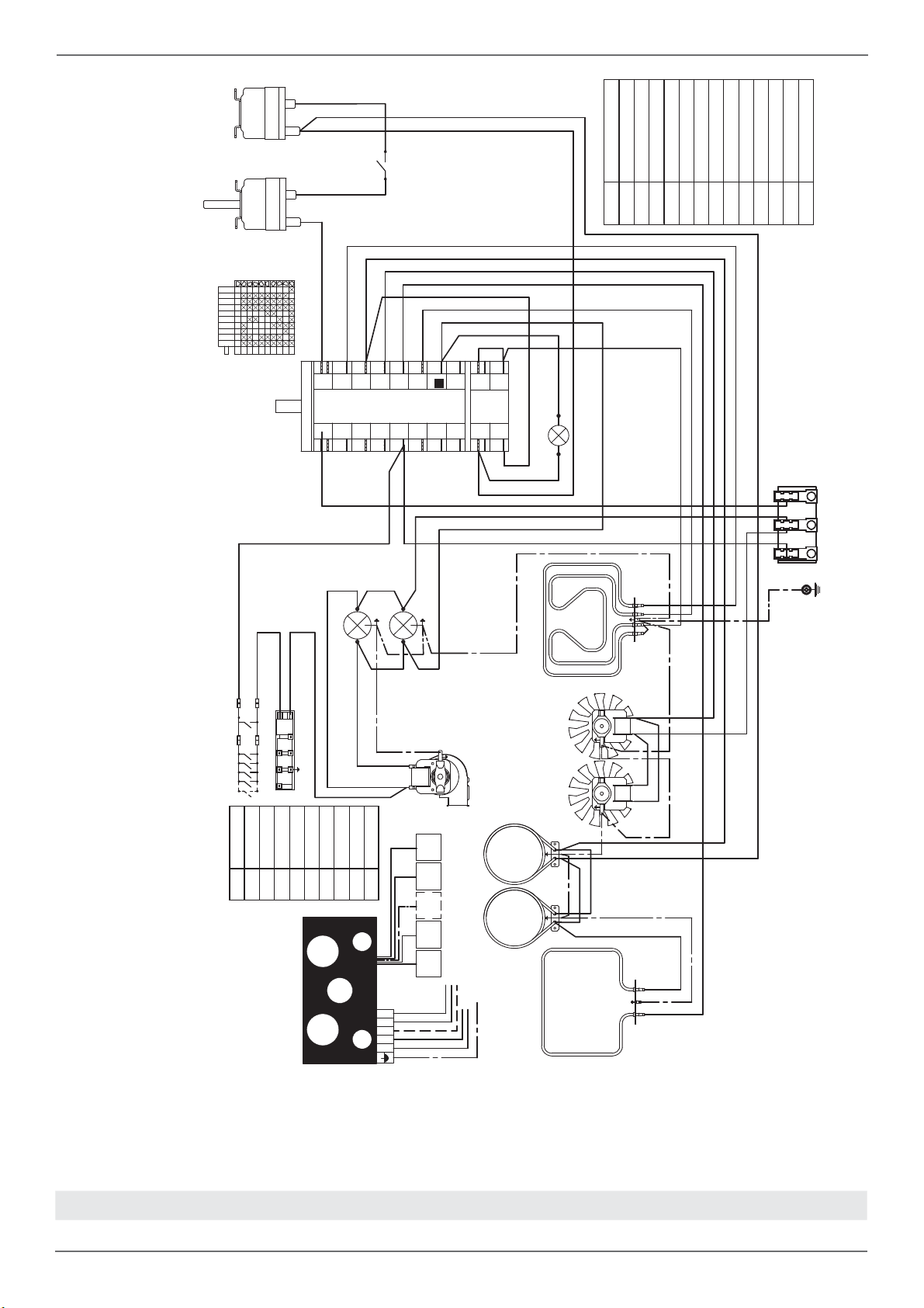
EG
M
L1 N L2
GROUND
LF
LF
MVMV
MVT
down
MVT
up
PT
RG+RC
RP
RCRC
Simb. Description
mBrown
rRed
gv Green
vViolet
gr Grey
aOrange
nBlack
bBlue
bi White
COLOURS
Simb. Description
B Thermal cut-out
CMV Cooling fan air sensor switch
DL Door Lock - Door Switch
EG Electronic Gauge
FS Oven Function Selector
G Spark Generator
IGN Ignition Micro switches
TS Oven Temperature Selecton
K Termal cut out
LF Oven lamp
MTerminal Block
MT Meat Probe
MV Fan motor
MVT Cooling fan motor
PT Oven sensor Temp. (PT1000)
RC Round element
RC+RG Upper/grill element
LEGENDA
CN1- 1....6
1..4
CN2
CN21
1.3
CN24
1.3
CN23
CN30
CN22 -3.1
CN27 - 6.....1
CN28 - 6.....1
DL
to M-L1
to CN27 - 6
to CN27 - 5
to CN26 - 2
to CN26 - 3
to M-L1
to DL
to DL
to M-N
to M-L1
TS
to CN23 - 3
to CN23 - 2
to CN23 - 1
FS
to CN23 - 3
to CN23 - 2
to CN23 - 1
to DL
to DL
to M-L1
to M-N
to GROUND
TSS
1
2
K
B
n
to M-L1
to M-L1
to M-L1
CMV
down
CMV
up
R1 R2 R3 R4 R5
1
2
3
4
5
12345
INDUCTION COOKTOP
[to M-L2]
[to M-L1]
[to ground]
MT
A
B
a
a
v
v
b
b
gr
gr
r
r
n
n
n
n
n
bi
bi
bi
bi
b
r
a
bi
r
n
n
n
bi
to MV
to MV
to MV
to MV
to M-GROUND
to RP
NOT USED
/ Wiring diagram
DFS
13
/ Installation
APPLIANCE INSTALLATION
Unpacking the range
• Remove all packing materials from the ship-
ping pallet but leave the adhesive-backed foam
layer over brushed-metal surfaces to protect it
from scratches until the range is installed in its
fi nalposition. Only the fi lm on the side panels
should be removed before inserting the range
between the cabinets.
• Examine the appliance after unpacking it. In the
event of transport damage, do not plug it. Take
pictures of the damage and report it immedia-
tely to the freight forwarder.
• Remove the oven door(s). This will reduce the
weight of the range.
• The grates, griddle plate, burner caps, and oven
racks should be removed to facilitate handling.
• Before moving the range, protect the fl oor to
prevent damage.
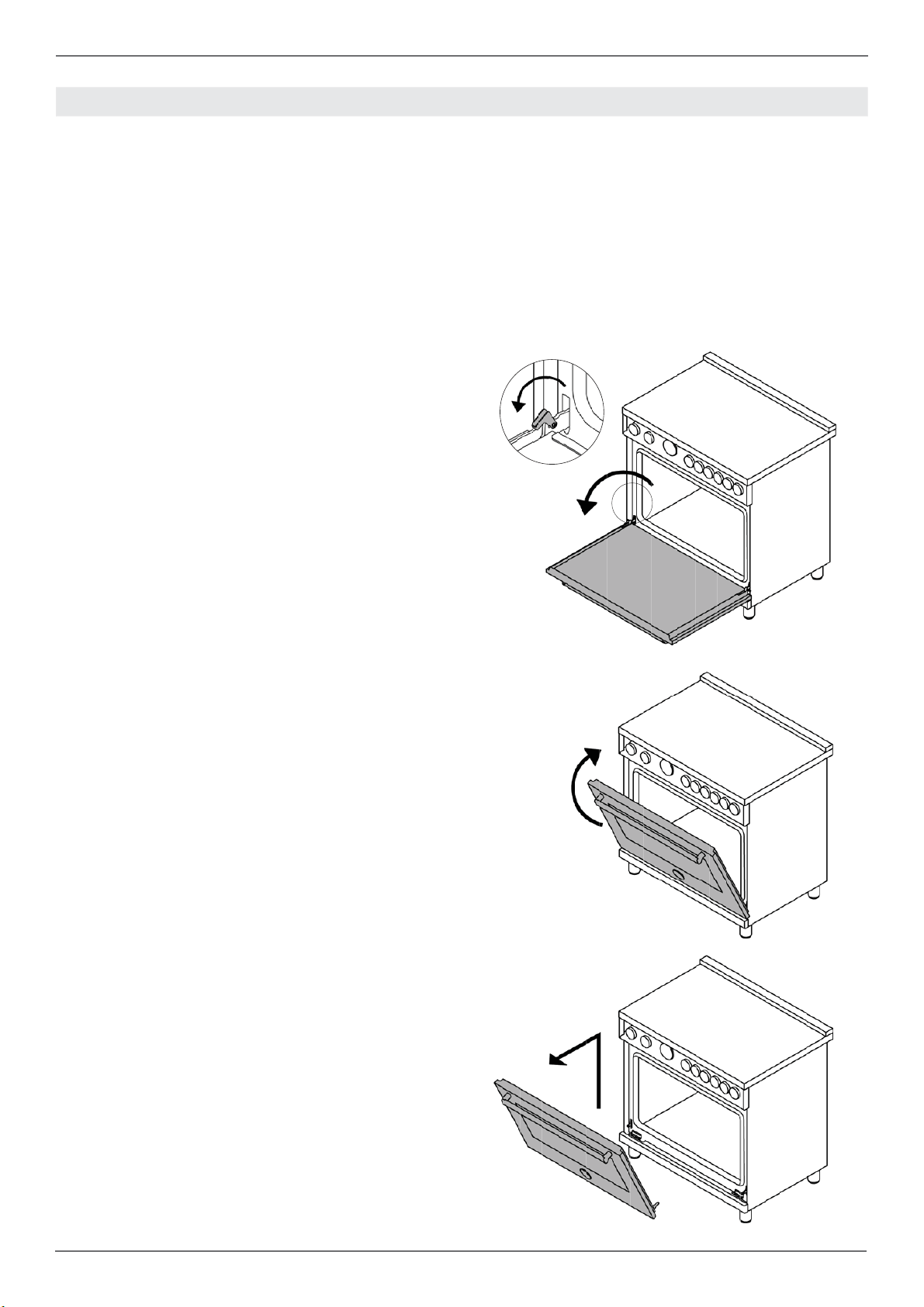
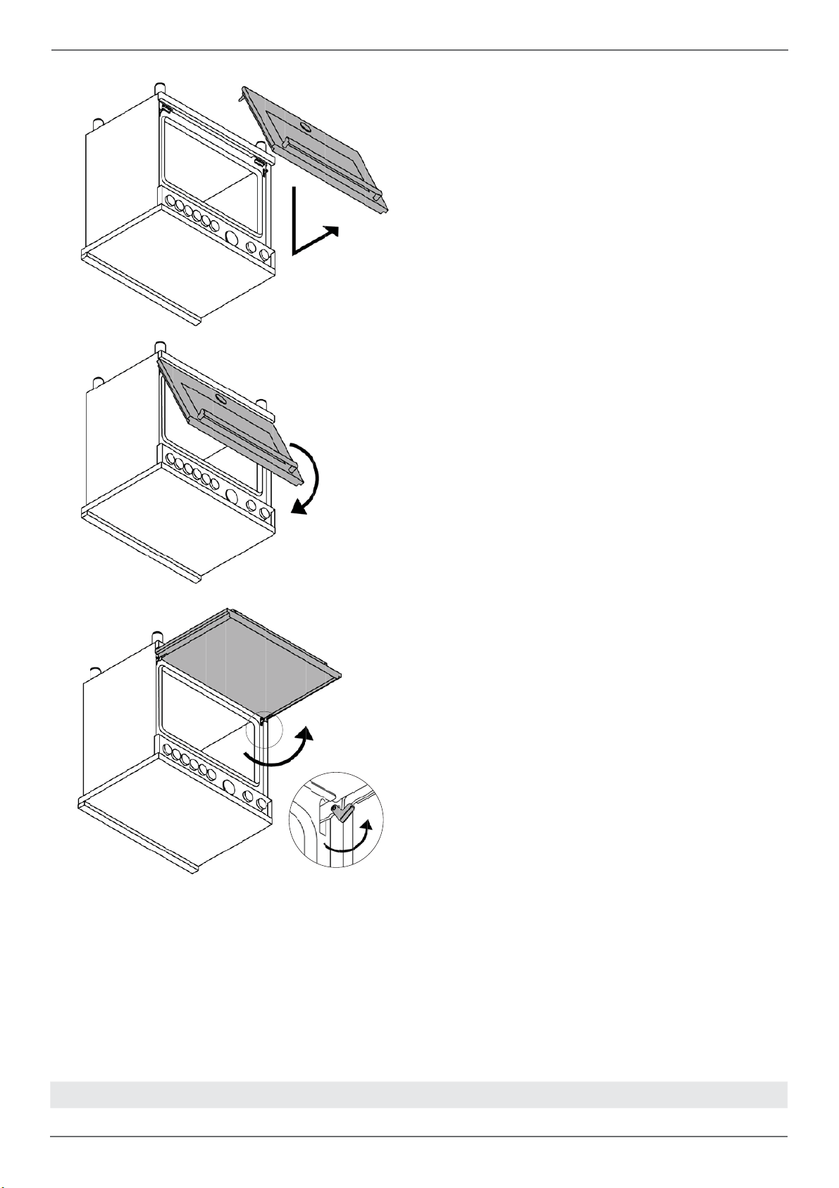
REMOVING THE OVEN DOOR
Prepare the door for removal. Flip up the locking
clamps on each door hinge. Slowly shut the door
until the protruding clamps stop the movement.
Pull oven door upwards and remove.
Do not lift or carry the oven door by its handle!
This may damage the hinges.
INSTALLATION
2
1
3
14
/ Installation
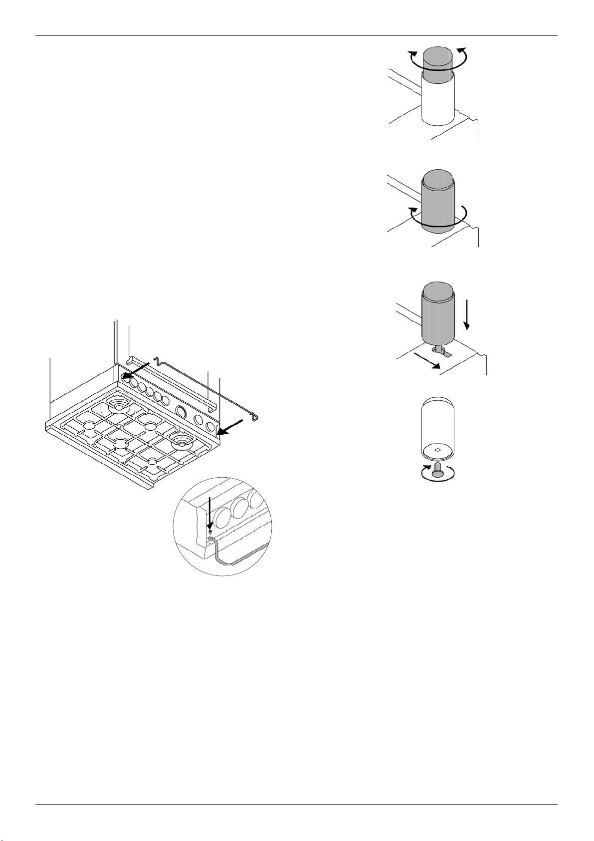
INSTALLING THE LEGS
Bertazzoni ranges must be used only with the legs
properly installed.
Four height-adjustable legs are supplied with the
range in the polysterene container situated over
the appliance.
Before installing the legs, position the appliance
near its fi nal location as the legs are not suitable
for moving the appliance over long distances.
After unpacking the range, raise it enough to in-
sert the legs in the appropriate receptacles situa-
ted on the lower part of the appliance. Lower the
range gently to keep any undue strain from legs
and mounting hardware. If possible use a pallet or
lift jack instead of tilting the unit.
Adjust leg height to the desired level by twisting
the inside portion of the leg assembly until the pro-
per height is reached. Check with a level that the
cooktop is perfectly level.
INSTALLING THE WORKTOP
FRONTGUARD
To increase the clearance between the front edge
of the worktop and the burners, it is possible to
install a front guard for the worktop.
To install the front guard,
• Locate the two fi xing holes on the end of the
front guard.
• Locate the two fi xing holes on the bottom facet
of the worktop
• Fix the front guard with it’s two screws
1
2
3
4
15
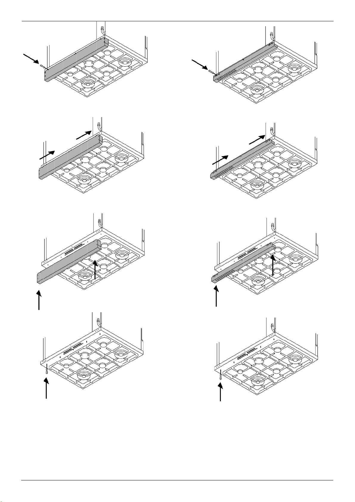
INSTALLING THE ISLAND TRIM
The island trim must be installed prior to operation
of the appliance for appropriate ventilation of the
oven compartment.
The island trim is only placed on the cooktop, re-
move all tape and packaging before installing it.
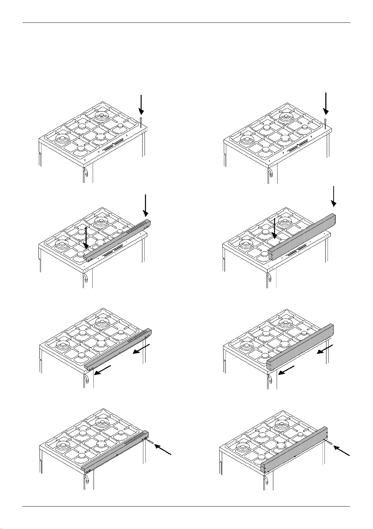
INSTALLING BACKGUARD (OPTIONAL)
The backguard must be installed prior to opera-
tion of the appliance for appropriate ventilation of
the oven compartment.
The backguard is an optional contact you dealer
for buying it.
/ Installation
1 1
2 2
3
3
4 4
16
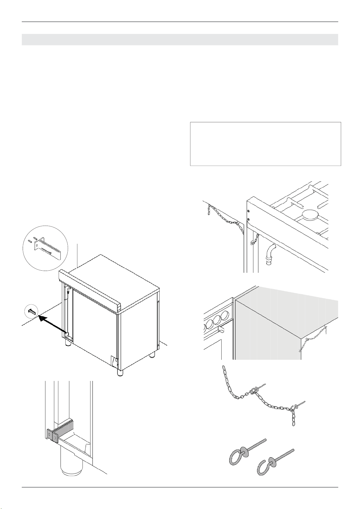
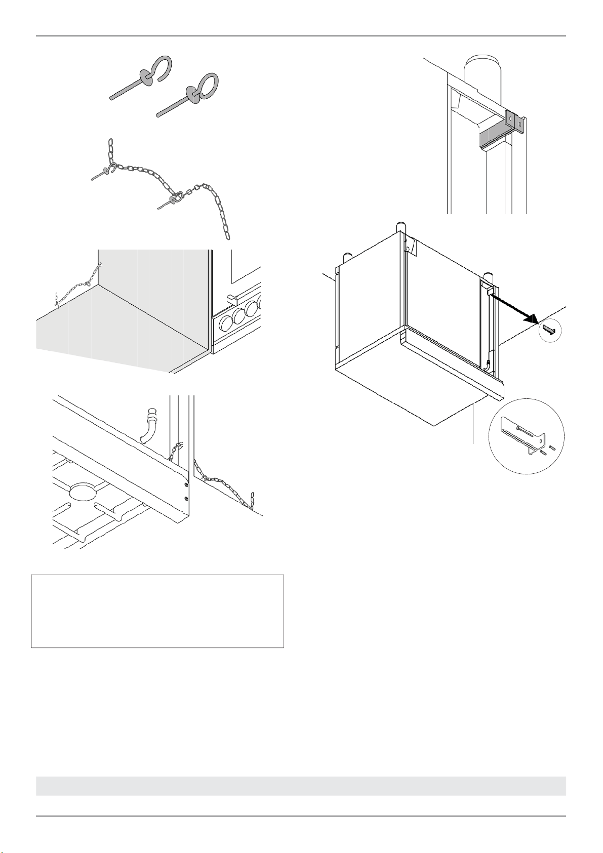
ANTI-TIP BRACKETS
The anti-tip bracket shipped with the range must
be properly secured to the rear wall as shown in
the picture below.
The height of the bracket from the fl oor must be
determined after the range legs have been adju-
sted to the desired height and after the range has
been levelled.
• Measure the distance from the fl oor to the
bottom of the anti-tip bracket receptacle on the
back of the appliance.
• Position the anti-tip brackets on the wall at
the desired height plus 1/8” (0.32 cm). The
brackets must be placed at 2”5/16 (6,0 cm)
from the side of the range.
• Secure the brackets to the wall with appropria-
te hardware.
• Slide the range against the wall until the
brackets are fully inserted into their recepta-
cles on the back of the range.
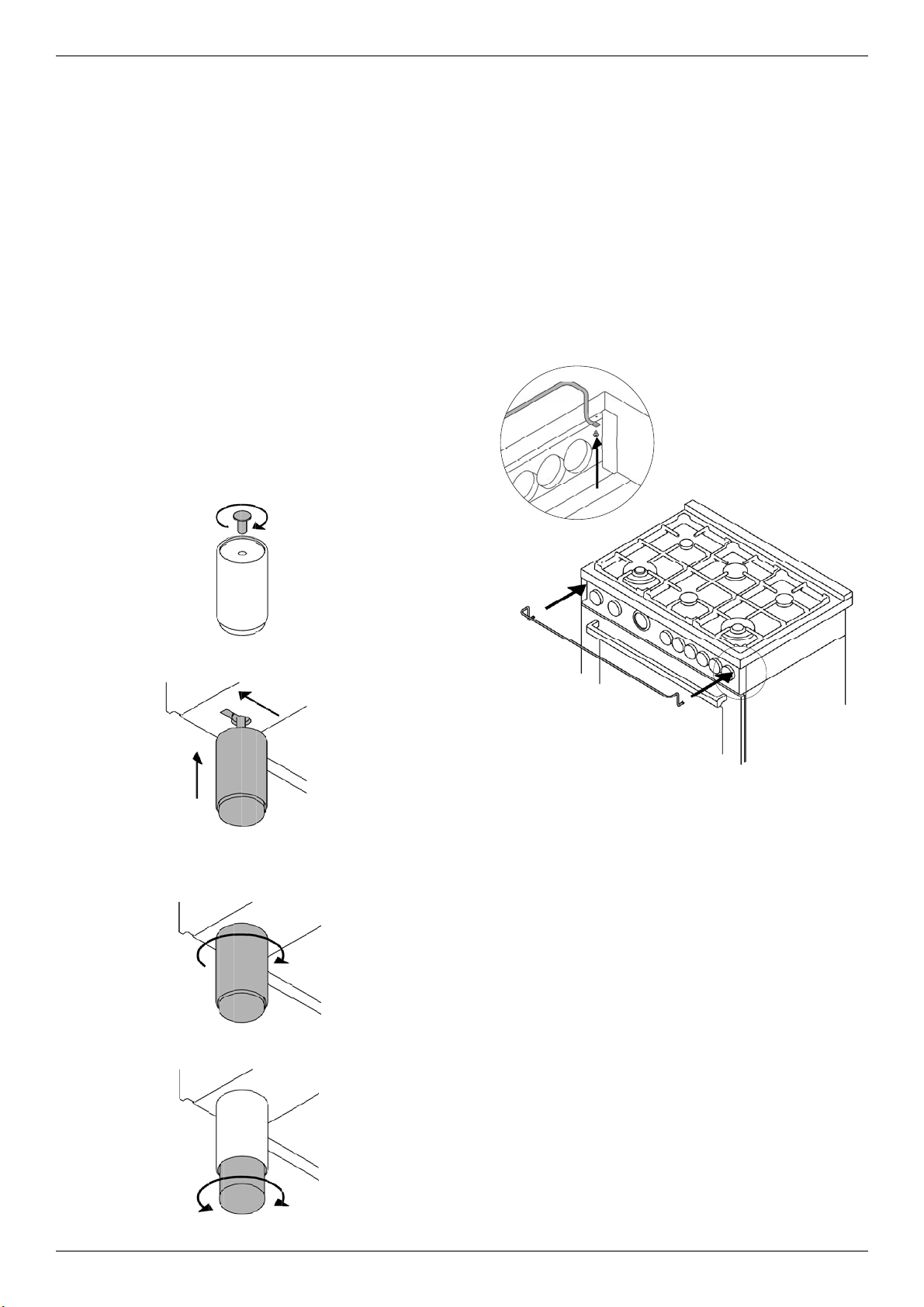
ANTI/TILT CHAIN
The anti-tilt chain shall be installed on right or left
side alternatively according below instructions.
The chain shall be hand pulled and fi xed to open
hook through closed ring.
Disengage the chain prior to moving the appliance
for service.
Attention:
Once servicing operation have been completed
the anti-tilt devices ( brackets and chain) shall be
re-engaged according above instruction/installa-
tions.
INSTALLING THE ANTI/TIP DEVICES
1
2
CLOSED RING OPEN HOCK
/ Installing the anti/tip devices

17
INSTALLATION CHECKLIST FINAL PREPARATION
A qualifi ed installer should carry out the following
checks:
Range mounted on its legs
Island trim or Backguard attached accor-
ding to instruction
Anti-tip device properly installed
Clearance to cabinet surfaces as manu-
facturer’s guideline
• Before using the oven, remove any protective
wrap from the stainless steel.
• All stainless steel body parts should be wiped
with hot, soapy water and with a liquid stainless
steel cleanser.
• If buildup occurs, do not use steel wool, abrasi-
ve cloths, cleaners, or powders!
• If it is necessary to scrape stainless steel to re-
move encrusted materials, soak with hot, wet
cloths to loosen the material, then use a wood
or nylon scraper.
• Do not use a metal knife, spatula, or any other
metal tool to scrape stainless steel! Scratches
are almost impossible to remove.
• Before using the oven for food preparation,
wash the cavity thoroughly with a warm soap
and water solution to remove fi lm residues and
any dust or debris from installation, then rinse
and wiped dry.
Attention!
When using the oven for the fi rst time it
should be operated for 15-30 minutes at a tem-
perature of about 500°F/260°C (main oven) or
440°F/227°C(auxiliary oven) without cooking
anything inside in order to eliminate any moi-
sture and odours from the internal insulation.
/ Installation checklist / fi nal preparation

18
BERTAZZONI SERVICE
Bertazzoni is committed to providing the best cu-
stomer and product service. We have a dedicated
team of trained professionals to answer your ne-
eds.
If you own a Bertazzoni appliance and need ser-
vice in the US or Canada please use the following
contact information:
e-mail: [email protected]
Telephone - Monday through Friday,
7.30am to 7.30pm EST (except US public holidays).
US 866-905-0010
WESTERN CANADA 866-905-0010 (BC,AB,SK,MB)
EASTERN CANADA 800-561-7265 (ON,QC,NL,NB,NS,PE)
/ Bertazzoni service

18
ASSISTANCE BERTAZZONI
Bertazzoni s'engage à fournir le meilleur service
clients et la meilleure assistance produits possi-
bles. Notre équipe de professionnels dévoués et
formés répondra à vos besoins.
Si vous disposez d'un appareil Bertazzoni et
souhaitez bénéfi cier d'une assistance aux État-
s-Unis ou au Canada, utilisez les coordonnées
suivantes :
e-mail : [email protected]
Tél. - Lundi au vendredi,
7h30 à 19h30 EST (sauf jours fériés aux États-Unis).
États-Unis 866-905-0010
OUEST DU CANADA 866-905-0010 (BC, AB, SK, MB)
EST DU CANADA 800-561-7265 (ON, QC, NL, NB, NS, PE)
/ Assistance Bertazzoni

17
LISTE DE CONTRÔLE POUR L'INSTALLATION PRÉPARATION FINALE
Un installateur qualifi é devra réaliser les contrôles
suivants :
La cuisinière est-elle installée sur ses pieds ?
La garniture ou la protection arrière est-elle
fi xée conformément aux instructions fournies ?
Les dispositifs anti-basculement sont-ils
correctement installés ?
Le dégagement par rapport aux surfaces
des meubles est-il conforme aux consignes
du fabricant ?
Le raccordement à la terre a-t-il été
correctement réalisé ?
• Avant d'utiliser le four, retirer tout fi lm protecteur
éventuellement présent sur les surfaces en
acier inoxydable.
• Toutes les parties du corps en acier inoxydable
doivent être nettoyées avec de l'eau chaude
savonneuse et un détergent liquide adapté à
l'acier inoxydable.
• En présence de dépôts, ne pas utiliser de laine
d'acier, de linges abrasifs, de produits ou de
poudres nettoyants.
• Si l'acier inoxydable doit être gratté pour en
retirer les incrustations, mouiller avec un chiff on
humide et chaud pour ramollir le dépôt, puis
utiliser une raclette en bois ou en nylon.
• Ne pas utiliser de couteau, de spatule ou tout
autre ustensile en métal pour gratter l'acier
inoxydable ! Les rayures sont très diffi ciles à
enlever.
• Avant d'utiliser le four pour la préparation de
nourriture, nettoyer minutieusement la cavité
avec une solution d'eau chaude et de savon afi n
d'éliminer les résidus de matériaux d'emballage
et tout débris ou poussière résultant de
l'installation, puis rincer et sécher.
Attention !
Lors de la première utilisation du four, celui-ci
doit être mis en marche pendant 15-30 minutes
à une température d'environ 500°F/260 °C (four
principal) ou 440°F/227 °C (four auxiliaire)
sans rien cuire à l'intérieur, afi n d'éliminer les
éventuelles moisissures et odeurs d'isolation
interne.
/ Liste de contrôle pour l'installation / Préparation fi nale
16
SUPPORTS ANTI-BASCULEMENT
Les supports anti-basculement fournis avec la
cuisinière doivent être correctement fi xés au
mur postérieur, comme indiqué sur la fi gure ci-
dessous.
La hauteur correcte des supports est déterminée
après avoir réglé les pieds de la cuisinière et une
fois celle-ci nivelée.
• Mesurer la distance entre le sol et le bas
du logement du support anti-basculement à
l'arrière de la cuisinière.
• Positionner les supports anti-basculement
sur le mur à la hauteur souhaitée plus
1/8” (0,32 cm). Les supports doivent être
positionnés à 2”5/16 (6,0 cm) par rapport au
côté de la cuisinière.
• Fixer les supports au mur à l'aide d'outils
adaptés.
• Faire glisser la cuisinière contre le mur jusqu'à
ce que les supports soient complètement insérés
dans leurs logements à l'arrière de la cuisinière.
CHAÎNE ANTI-BASCULEMENT
La chaîne anti-basculement doit être fi xée au côté
gauche ou droit, selon les instructions ci-après.
Tirer la chaîne manuellement à travers l'anneau et
l'insérer dans le crochet.
Défaire la chaîne avant tout déplacement de la
cuisinière en vue d'une opération d'entretien.
Attention :
Une fois les opérations d'entretien terminées, les
dispositifs anti-basculement (supports et chaîne)
doivent être remis en place conformément aux
instructions ci-dessus.
INSTALLATION DES DISPOSITIFS ANTI-BASCULEMENT
1
2
ANNEAU CROCHET
/ Installation des dispositifs anti-basculement
15
INSTALLATION DE LA GARNITURE
La garniture doit être installée avant toute
utilisation de la cuisinière afi n de garantir la
ventilation appropriée du compartiment du four.
La garniture est uniquement positionnée sur la
surface de cuisson. Retirer tous les rubans et
matériaux d'emballage avant son installation.
Avant l’installation, portez des gants de sécurité.
INSTALLATION DE LA PROTECTION
ARRIÈRE (EN OPTION)
La protection arrière doit être installée avant
toute utilisation de la cuisinière afi n de garantir la
ventilation appropriée du compartiment du four.
La protection arrière est un équipement en option.
Contactez votre revendeur pour vous la procurer.
Avant l’installation, portez des gants de sécurité.
/ Installation
1 1
2 2
3
3
4 4
14
/ Installation
INSTALLATION DES PIEDS
Les cuisinièresBertazzoni ne doivent être utilisées
qu'une fois leurs pieds correctement installés.
Quatre pieds réglables en hauteur sont fournis avec
la cuisinière dans le conteneur en polystyrène placé
sur le dessus de l'appareil.
Avant d'installer les pieds, positionner la cuisinière
à proximité de son emplacement fi nal ; les pieds
ne doivent pas être utilisés pour la déplacer sur de
longues distances.
Après avoir déballé la cuisinière, la soulever
suffi samment afi n de pouvoir insérer les pieds dans
les logements correspondants situés sous l'appareil.
Abaisser lentement la cuisinière pour éviter toute
sollicitation excessive sur les pieds et le matériel de
montage. Si possible, utiliser une palette ou un cric
plutôt que de faire basculer la cuisinière.
Régler la hauteur des pieds au niveau souhaité en
tournant la partie interne du pied. À l'aide d'un niveau,
vérifi er que la surface de cuisson est parfaitement
plane.
INSTALLATION DE LA PROTECTION
FRONTALE DE LA SURFACE DE CUISSON
Afi n d’augmenter l’espace entre le bord frontal de
la surface de cuisson et les brûleurs, il est possible
d’installer une protection frontale pour la surface de
cuisson.
Pour installer la protection frontale:
• Repérer les deux trous de fi xation aux extrémités
de la protection frontale.
• Repérer les deux trous de fi xation sur la face
inférieure de la surface de cuisson.
• Fixer la protection frontale à l’aide de ses deux
vis.
1
2
3
4
13
/ Installation
INSTALLATION DE L'APPAREIL
Déballage de la cuisinière
• Retirer tous les matériaux d'emballage de la
paletted'expédition sans toucher à la mousse
postérieure adhésive sur les surfaces en métal
brossé, afi n de protéger la cuisinière des rayures
jusqu'à son installation à son emplacement fi nal.
Ne retirer que le fi lm protégeant les panneaux
latéraux avant de positionner la cuisinière entre
les meubles de cuisine.
• Examiner la cuisinière après l'avoir déballée. En
cas de dommage résultant du transport, ne pas
la brancher. Prendre des photos du dommage
et en informer immédiatement le transporteur.
• Retirer la ou les portes du four. Cela réduira le
poids de la cuisinière.
• Retirer les grilles, plaques et chapeaux des
brûleurs pour faciliter le déplacement de la
cuisinière.
• Avant de la déplacer, protéger le sol pour éviter
tout dommage.
RETRAIT DE LA PORTE DU FOUR
Préparer la porte en vue de son retrait. Rabattre
les fi xations sur chaque charnière de porte.
Fermer lentement la porte jusqu'à ce que la
fi xation saillante ne bloque le mouvement.
Tirer la porte vers le haut et la retirer.
Ne pas soulever ou tirer la porte par sa poignée !
Cela pourrait endommager les charnières.
INSTALLATION
2
1
3
12
to CN1 - 1
to CN1 - 2
to CN1 - 3
to CN1 - 4
to CN1 - 5
to CN1 - 6
EG
M
L1 N L2
GROUND
LF
LF
MVMV
MVT
down
MVT
up
PT
RG+RC
RP
RCRC
Simb. Description
mBrown
rRed
gv Green
vViolet
gr Grey
aOrange
nBlack
bBlue
bi White
COLOURS
Simb. Description
B Thermal cut-out
CMV Cooling fan air sensor switch
DL Door Lock - Door Switch
EG Electronic Gauge
FS Oven Function Selector
G Spark Generator
IGN Ignition Micro switches
TS Oven Temperature Selecton
K Termal cut out
LF Oven lamp
MTerminal Block
MT Meat Probe
MV Fan motor
MVT Cooling fan motor
PT Oven sensor Temp. (PT1000)
RC Round element
RC+RG Upper/grill element
LEGENDA
CN1- 1....6
1..4
CN2
CN21
1.3
CN24
1.3
CN23
CN30
CN22 -3.1
CN27 - 6.....1
CN28 - 6.....1
DL
to M-L1
to CN27 - 6
to CN27 - 5
to CN26 - 2
to CN26 - 3
to M-L1
to DL
to DL
to M-N
to M-L1
TS
to CN23 - 3
to CN23 - 2
to CN23 - 1
FS
to CN23 - 3
to CN23 - 2
to CN23 - 1
to DL
to DL
to M-L1
to M-N
to GROUND
TSS
1
2
K
B
n
to M-L1
to M-L1
to M-L1
CMV
down
CMV
up
R1 R2 R3 R4 R5
1
2
3
4
5
12345
INDUCTION COOKTOP
[to M-L2]
[to M-L1]
[to ground]
MT
A
B
a
a
v
v
b
b
gr
gr
r
r
n
n
n
n
n
bi
bi
bi
bi
b
r
a
bi
r
n
n
n
bi
to MV
to MV
to MV
to MV
to M-GROUND
to RP
NOT USED
/ Schéma de câblage
DFS
11
/ Schéma de câblage
SCHÉMA DE CÂBLAGE
Les schémas de câblage électrique fi gurent à l'arrière de la cuisinière et ne peuvent être retirés que par un
technicien de maintenance, qui doit les remettre en place une fois l'entretien réalisé.
DFM
G
IGN
bi
S
LF
MVT
T
RG+RC
RP
n
a
b
b
M
L1 N L2
GROUND
TSS
1
2
CMV
P1
Commutatore.9+0
1
P2
P3
P4
P5
P6
P7
P8
P1
P2
2
3
4
5
6
7
8
1
2
P2
P1
P8
P7
P6
P5
P4
P3
P2
1
0
4
3
P1
2
5
6
7
8
9
COM
RCRC
MV MV
LF
Simb. Description
mBrown
rRed
gv Green
v Violet
gr Grey
aOrange
nBlack
bBlue
bi White
COLOURS
v
v
n
bi
bi
a
a
b
r
a
gr
b
v
b
a
bi
r
Simb. Description
IGN Ignition Micro switches
COM Oven Function Selector
CMV Cooling fan air sensor switch
LF Oven lamp
MTerminal Block
MV Fan motor
MVT Cooling fan motor
RC Round element
RC+RG Upper/grill element
RP Lower element
S Signal lights
TSS Safety Thermostat
TThermostat
LEGENDA
[to ground]
[to A-L1]
[to A-L2]
R1 R2 R3 R4 R5
1
2
3
4
5
12345
INDUCTION COOKTOP
10
/ Raccordement électrique
RECEPTACLE DE CONNEXION A QUATRE
FILS (NEMA 14-50R)
RECEPTABLE DE CONNEXION A TROIS FILS
(NEMA 14-50R)
Vérifi er les exigences applicables des codes
locaux de votre pays, pour voir laquelle des
options ci-dessous devra être utilisée pour relier
les connexions d’alimentation du réceptacle à la
terre :
OPTION 1 – Connexion à QUATRE fi ls :
- Connecter la borne L1 du réceptacle au câble
d’alimentation électrique entrant NOIR (L1-fi l
chaud)
- Connecter la borne L2 du réceptacle au câble
d’alimentation électrique entrant ROUGE (L2-fi l
chaud)
- Connecter la borne NEUTRE du réceptacle au
câble d’alimentation électrique entrant NEUTRE
(BLANC)
- Connecter la borne de TERRE du réceptacle au
câble d’alimentation électrique de TERRE (VERT)
OPTION 2 – Connexion à TROIS fi ls :
- Connecter la borne L1 du réceptacle au câble
d’alimentation électrique entrant NOIR (L1-fi l
chaud)
- Connecter la borne L2 du réceptacle au câble
d’alimentation électrique entrant ROUGE (L2-fi l
chaud)
- Connecter la borne NEUTRE et la borne de
TERRE du réceptacle au câble d’alimentation
électrique entrant NEUTRE (BLANC)
NE PAS UTILISER DE RALLONGE AVEC CET
APPAREIL. LE FAIRE PEUT ENTRAINER UN
INCENDIE, UN CHOC ELECTRIQUE OU AUTRE
DOMMAGE CORPOREL.
L’appareil est fourni avec un cordon d’alimentation
à 4 fi ls avec des bornes à anneau (L1, L2, N,
Terre), adapté pour des usages conformes aux
normes UL/CSA indiquées (type SRDT/DRT 2 x
6 AWG (L1, L2) + 2 x 8 AWG (N, Terre)), d’une
puissance nominale de 300 V , 40 ou 50 A avec
une prise enfi chable type NEMA 14-50P ; câble
de 1,5 m de long ; si le cordon d’alimentation doit
être remplacé, il le sera par un cordon identique
qui aura les mêmes caractéristiques techniques
et en suivant scrupuleusement les instructions (et
schémas) ci-dessous :
9
/ Conditions d'installation / Raccordement électrique
ÉLECTRICITÉ
Une prise électrique montée horizontalement et
correctement mise à la terre doit être installée à
une hauteur maximale de 3” (7,6 cm) et minimale
de 2” (5 cm) par rapport au sol, et à une distance
maximale de 8” (20,3 cm) par rapport au côté
gauche du produit (en lui faisant face).
Vérifi er les dispositions des règlementations
locales.
DANGER !
RISQUE DE DÉCHARGE ÉLECTRIQUE !
Couper l'alimentation électrique au niveau
du disjoncteur ou du tableau à fusibles avant
d'installer l'appareil.
L'appareil doit être correctement mis à la terre.
Utiliser uniquement des conducteurs en
cuivre.
Le non-respect de ces instructions pourrait
entraîner de graves blessures, voire la mort.
Mise à la terre
L'appareil est équipé d'une prise à trois broches
qui garantit une protection contre les décharges
électriques. Elle doit être branchée directement à
une prise murale correctement mise à la terre. Ne
pas couper ou retirer la broche de terre de cette
prise.
Attention
Étiqueter chaque câble avant de les débrancher
pour eff ectuer des contrôles d'entretien.
Des erreurs de câblage peuvent entraîner un
fonctionnement incorrect et dangereux.
Vérifi er le bon fonctionnement de la cuisinière
après l'entretien.
L’appareil sera branché à un système électrique
monophasé à 120/208 Vca ou 120/240 Vca,
fréquence de 60 Hz.
Brancher un réceptacle d’alimentation électrique
adapté à l’aide d’une prise type NEMA 14-50R,
capable de supporter une charge d’au moins
30 A (par ligne), conformément aux exigences
applicables des codes locaux (système de
connexion d’alimentation à trois ou quatre fi ls) ;
voir schémas.
CONDITIONS D'INSTALLATION RACCORDEMENT ÉLECTRIQUE
zone réservée au branchement
Type Vca évaluation Fournit.
électrique
30” IND-
DFM
120/208V
120/240V
10300W 46A
11000W 48A
40A
40A
30” IND-
DFS
120/208V
120/240V
11700W 53A
13000W 56A
40A
40A
36” IND-
DFM
120/208V
120/240V
14000W 62A
14800W 64A
40A
40A
36” IND-
DFS
120/208V
120/240V
15600W 70,5A
17000W 73,5A
50A
50A
8
/ Espace de dégagement
ESPACE DE DÉGAGEMENT
Installation adjacente à des meubles de cuisine
Cette cuisinière peut être installée à proximité
directe de plans de travail avec meubles intégrés
(36” ou 91,5 cm par rapport au sol).
Pour un aspect optimal, la surface de la cuisinière
doit être au même niveau que celle du plan de
travail avec meuble intégré. Pour ce faire, régler la
hauteur de l'appareil en agissant sur les dispositifs
de réglage des pieds.
ATTENTION : la cuisinière NE DOIT PAS être
installée à proximité directe des murs de la cuisine,
de meubles ou d'appareils hauts, ou d'autres
surfaces verticales de plus de 36” (91,4 cm) de
hauteur. Dans ces cas, l'espace latéral doit être
d'au moins 6” (15,2 cm).
Les meubles muraux présentant cet espace latéral
minimum doivent être installés à 18” (45,7 cm) au-
dessus du plan de travail, avec une hauteur de
plan de travail comprise entre 35 ½” (90,2 cm)
et 37 ¼” (94,6 cm). La profondeur maximale des
meubles muraux au-dessus de la cuisinière doit
être de 13” (33 cm).
Meuble de cuisine
En cas d’installation de toekick, vérifi ez que la
somme des zones de découpe correspond à la
ventilation recommandée (L)
30” surface 40 sq. inches ( 25840 mm2)
36” surface 51 ½ sq. inches ( 33107 mm2)
48” surface 73 ½ sq.inches ( 47547 mm2)
La zone grisée derrière la cuisinière indique
l'espace minimum à respecter par rapport à la
surface de cuisson. Aucun matériau combustible
ne doit se trouver dans cette zone.
12” (305 mm) min. par rapport aux surfaces
combustibles avec garniture affl eurante.
Pour des installations autonomes, la surface de
travail doit être dotée d'un bord saillant faisant la
jonction avec la partie arrière de la garniture.
Hotte métallique
A
B
C
D
E
F
A
B
C
D
E
F
G
H
30’’ (76,2 cm)
36’’ (91,5 cm) hotte avec matériaux combustibles
13’’ (33,0 cm)
18’’ (45,7 cm)
35’’ 1/2(90,2 cm) / 37”
1/4
(94,6 cm)
6’ (15,2 cm)
30’’ (76,2 cm)
25 1/2’’(65 cm) et 31 1/2’’ (80 cm)
13’’ (33,0 cm)
18’’ (45,7 cm)
35’’ 1/2(90,2 cm) / 37”
1/4
(94,6 cm)
6” (15,2 cm)
12”(30,50 cm)
1” 9/16(4 cm)
A
F
D
B
C
E
/
B
G
H
7
Cette cuisinière a un fonctionnement optimal
en cas d'installation avec une hotte d'extraction
Bertazzoni. Ces hottes, conçues pour être
associées à la gamme Bertazzoni, off rent un
aspect impeccable grâce à leur fi nition identique.
Avant d'installer la hotte d'extraction, consulter les
règlementations locales ou régionales en matière
de construction et d'installation pour connaître les
critères spécifi ques aux espaces de dégagement.
Pour plus d'informations, se reporter aux
instructions d'installation de la hotte fournies par
le fabricant.
Choisir les modèles de hotte et de ventilateur :
• En cas d'installation murale, la hotte doit
présenter une largeur au moins égale à celle de
la cuisinière. Lorsque l'espace le permet, il peut
être souhaitable d'installer une hotte plus large
que la cuisinière, pour une meilleure ventilation.
• En cas d'installations autonomes, la largeur de
la hotte doit dépasser celle de la cuisinière d'au
moins 3” (76 mm) de chaque côté.
Positionnement de la hotte :
• Pour une meilleure extraction des fumées et
des odeurs, le bord inférieur de la hotte doit
se trouver entre 25 1/2” (65 cm) et 31 1/2”
(80 cm) au-dessus de la surface de cuisson de
la cuisinière.
• Si la hotte contient des matériaux
combustibles (par ex. parement en bois), elle
doit être installée à au moins 36” (914 mm) au-
dessus de la surface de cuisson.
Air d'appoint :
En présence d'un volume élevé d'air de
ventilation, il est recommandé de disposer d'une
source d'air de remplacement extérieur. Cela est
particulièrement important pour les habitations
fermées hermétiquement et fortement isolées.
Consulter une entreprise de chauff age et de
ventilation qualifi ée.
/ Préparation de la ventilation / Spécifi cations
PRÉPARATION DE LA VENTILATION
SPÉCIFICATIONS
A
27''
/8
37''
1/2
MAX
1''
15/16
25''
/16
2''
1''
5/8
32''
3''
3/4
- 5''
1/2
5''
1''
5/8
1''
1/8
''
/
23''
7/8
3''
7/16
3 ''
11/16
2''
7/16
A
A
30’’ 36’’ 48’’

6
/ Avant l'installation
• L'appareil doit être installé uniquement par un
professionnel autorisé.
• Cet appareil doit être installé conformément
aux instructions d'installation du fabricant.
• L'appareil doit être installé conformément
aux normes et aux règlementations du pays
d'installation.
• Une fois installé, l'appareil doit être raccordé
à la terre conformément aux règlementations
locales ou, en leur absence, à la règlementation
américaine en matière d'électricité (NEC),
ANSI/NFPA 70.
Toutes les ouvertures et les trous dans le mur et le
plancher, derrière et sous l'appareil, doivent être
scellés avant l'installation de celui-ci.
Ventilation de la pièce
Il convient d'associer un ventilateur extracteur à
l'appareil. Celui-ci doit être installé conformément
aux normes locales et nationales en vigueur. Le
fonctionnement d'une hotte aspirante peut avoir
une incidence sur d'autres appareils de ventilation.
Elle doit être installée conformément aux normes
locales et nationales en vigueur.
Avertissement
Cet appareil ne doit pas être installé avec un
système de ventilation qui dirige l'air vers le bas,
en direction de la cuisinière. Ce type de système
de ventilation peut entraîner des incendies
et des problèmes de combustion, avec pour
conséquences des blessures, des dommages aux
biens et un fonctionnement non maîtrisé. Il n'existe
pas de restrictions concernant les systèmes de
ventilation qui dirigent l'air vers le haut.
Ne pas utiliser de sprays aérosols à proximité
de l'appareil en fonctionnement.
AVANT L'INSTALLATION

5
/ Étiquette signalétique
ÉTIQUETTE SIGNALÉTIQUE
L’étiquette signalétique indique le modèle et le
numéro de série de la cuisinière. Elle se trouve
sous le panneau de commande et à la dernière
page de ce manuel.
4
/ Avertissements
AVERTISSEMENTS
Pour un fonctionnement correct et en toute sécurité,
l'appareil doit être correctement installé et mis à la
terre par un technicien qualifi é. NE PAS tenter de
régler, réparer, réviser ou remplacer un composant
de l'appareil à moins que le présent manuel ne le
recommande spécifi quement. Toute autre intervention
doit être réalisée par un opérateur qualifi é.
POUR L'INSTALLATEUR : Avant d'installer l'appareil
Bertazzoni, veuillez lire attentivement ces instructions.
Cet appareil doit être installé conformément aux
instructions d'installation du fabricant. Ces instructions
doivent être laissées à la disposition du propriétaire,
qui les conservera pour toute consultation future
ou en cas de visite d'un inspecteur. NE PAS retirer
les étiquettes, les avertissements ou les plaques
permanentes apposés sur le produit. Cela risquerait
d'annuler la garantie.
L'installation doit être conforme aux règlementations
locales.
La cuisinière N'A PAS été conçue pour être installée
dans des maisons préfabriquées (mobiles) ou des
caravanes.
NE PAS installer la cuisinière en extérieur.
L'appareil doit être correctement raccordé à la terre. Le
raccordement à la terre réduit le risque de décharge
électrique en fournissant un passage sécurisé au
courant électrique en cas de court-circuit.
Avertissement !
Pour éviter les risques de lésion, de blessure mortelle
ou de dommages aux biens, suivre scrupuleusement
les informations contenues dans ce manuel visant à
prévenir les incendies ou les explosions.
Avertissement !
Pour éviter les risques de lésion, de blessure
mortelle ou de dommages aux biens, suivre
scrupuleusement les informations contenues
dans ce manuel visant à prévenir les incendies
ou les explosions. NE PAS entreposer ou utiliser
de l'essence ou d'autres liquides et vapeurs
infl ammables à proximité de l'appareil.
REMARQUE : L'installation et l'entretien doivent
être réalisés par un installateur qualifi é, une agence
spécialisée ou un fournisseur de gaz.
DANGER ! RISQUE DE DÉCHARGE ÉLECTRIQUE !
Pour éviter les risques de décharge électrique, de
lésion ou de blessure mortelle, vérifi er que l'appareil
a été correctement mis à la terre, conformément aux
règlementations locales ou, en leur absence, à la
règlementation américaine en matière d'électricité
(NEC). ANSI/NFPA 70 – dernière édition.
Avertissement – risque de basculement
Les enfants et les adultes peuvent faire basculer
la cuisinière si celle-ci n'a pas été fi xée au mur, ce
qui pourrait entraîner des blessures mortelles. Pour
réduire le risque de basculement de l'appareil, celui-ci
doit être fi xé au moyen de dispositifs anti-basculement,
conformément aux instructions d'installation.
Remettre en place les dispositifs anti-bascule-
ment après tout déplacement de la cuisinière. Ne
pas utiliser la cuisinière si les dispositifs anti-ba-
sculement ne sont pas en place et enclenchés.
Ne pas utiliser la cuisinière si les dispositifs
anti-basculement n’ont pas été correctement
installés et enclenchés. Pour plus d’informations,
consulter les instructions d’installation.
Le non-respect des instructions d’instal-
lation peut occasionner des blessures
graves, voire mortelles, aux enfants et
aux adultes.
Ne PAS soulever la cuisinière par les poignées du
four, car cela pourrait endommager les charnières
de porte et entraîner une fermeture incorrecte de
la porte.
Ne PAS soulever la cuisinière en la saisissant par
le panneau de commande.
La cuisinière est lourde et doit être manipulée avec
les soins nécessaires. Pour tout déplacement
de la cuisinière, prévoir la présence d’au moins
deux personnes dotées d’équipements adaptés,
notamment des gants, afi n d’éviter de se blesser
ou d’endommager la cuisinière ou le sol.
Les bagues, montres et tout accessoire ample
susceptible d’endommager la cuisinière ou de se
coincer dans la cuisinière doivent être retirés.
Les surfaces cachées peuvent avoir des bords
tranchants. Faire très attention en cas de contact
avec l’arrière ou le dessous de la cuisinière.
Ne PAS positionner de diable ou de chariot sur
l’avant ou l’arrière de la cuisinière. Le positionner
sur le côté uniquement.
AVERTISSEMENT:
Cancer et Troubles de l’appareil repro-
ducteur-
www.P65Warnings.ca.gov.

3
/ Modèles
Modèles
MAST365INMXE
MAST365INSXT
Modèles
PROF304INMXE
PROF304INMXT
PROF304INSART
PROF304INSBIT
PROF304INSGIT
PROF304INSNET
PROF304INSROT
PROF304INSXT
PROF365INSART
PROF365INSBIT
PROF365INSGIT
PROF365INSNET
PROF365INSROT
PROF365INSXT

2
/ Table des matières
TABLE DES MATIÈRES
AVERTISSEMENTS ____________________________________________________________
ÉTIQUETTE SIGNALÉTIQUE _____________________________________________________
AVANT L'INSTALLATION ________________________________________________________
PRÉPARATION DE LA VENTILATION ______________________________________________
SPÉCIFICATIONS ______________________________________________________________
ESPACE DE DÉGAGEMENT ______________________________________________________
CONDITIONS D'INSTALLATION _________________________________________________
Électricité __________________________________________________________________
ACCORDEMENT ÉLECTRIQUE _________________________________________________
SCHÉMA DE CÂBLAGE ________________________________________________________
INSTALLATION ________________________________________________________________
Déballage de la cuisinière _____________________________________________________
Retrait de la porte du four _____________________________________________________
Installation des pieds _________________________________________________________
Installation de la protection frontale de la surface de cuisson ________________________
Installation de la garniture ____________________________________________________
Installation de la protection arrière (en option) ____________________________________
INSTALLATION DES DISPOSITIFS ANTI-BASCULEMENT _____________________________
Supports anti-basculement ____________________________________________________
Chaîne anti-basculement _____________________________________________________
LISTE DE CONTRÔLE POUR L'INSTALLATION ______________________________________
PRÉPARATION FINALE __________________________________________________________
ASSISTANCE BERTAZZONI ______________________________________________________
4
5
6
7
7
8
9
9
10
11
13
13
13
14
14
15
15
16
16
16
17
17
18

1
BERTAZZONI
MANUEL D'INSTALLATION
CUISINIÈRES ELECTRIQUE AUTONOMES
3100295
WWW.BERTAZZONI.COM