Loading ...
Loading ...
Loading ...
31
SERVICE AND MAINTENANCE
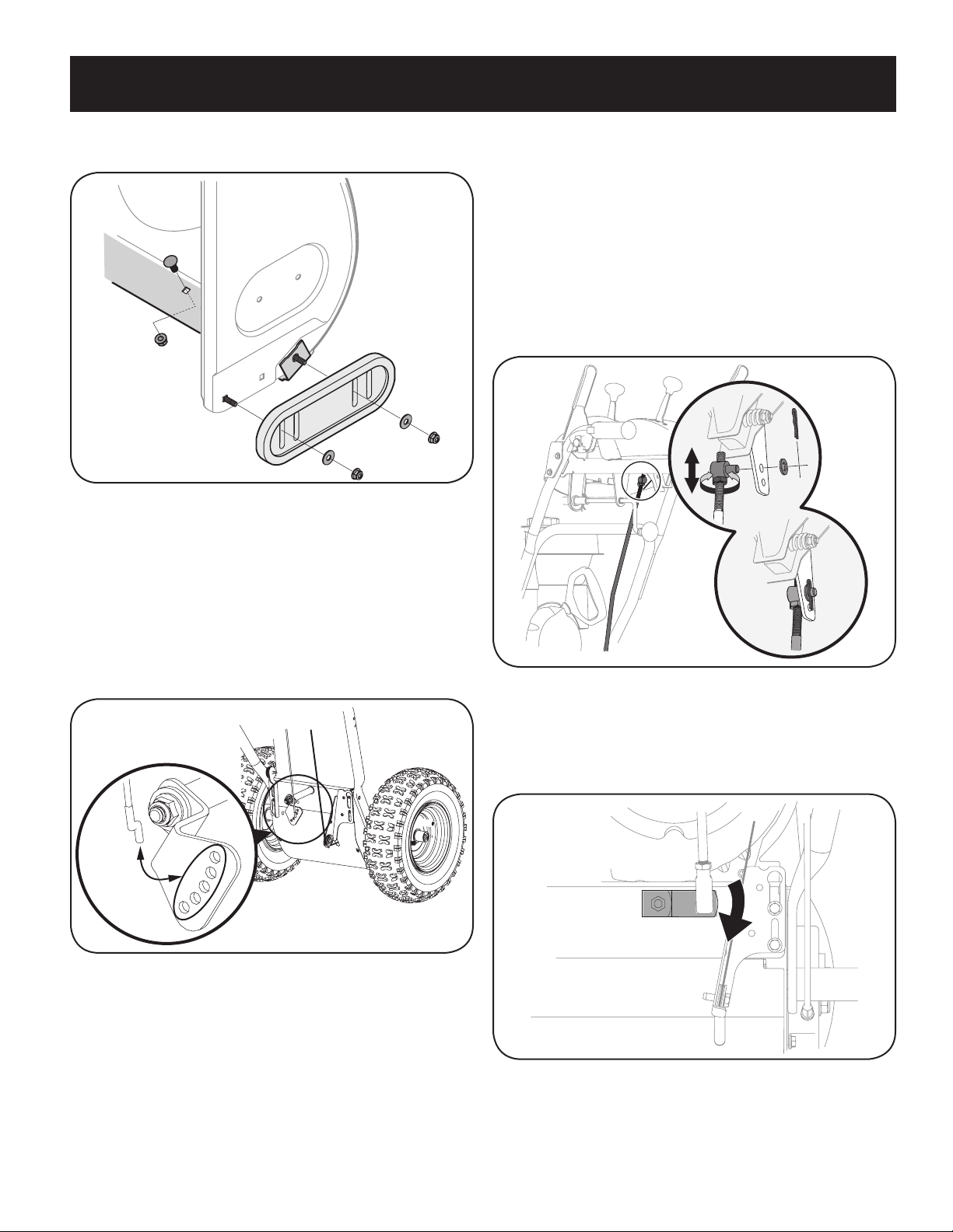
2. Reassemble new shave plate, making sure heads of carriage bolts are to the
inside of housing. Tighten securely. See Figure 59.
NOTE: Augers not shown for clarity.
Figure 59
Adjustments
Shift Cable
If full range of speeds (forward and reverse) cannot be achieved use the mounting
holes in the index bracket to adjust the shift cable tension as follows:
1. Place shift lever in fastest forward speed position (F6).
2. Lift the shift cable index bracket (a) up to create slack in the cable (b). See
Figure 60.
Figure 60
3. Disengage the Z fitting (c) from the index bracket.
4. Select new mounting hole and reinsert Z fitting into the index bracket.
Using the upper mounting holes will loosen the shift cable. Using the lower
mounting holes will tighten the shift cable.
5. Reinsert the Z fitting into the index bracket.
6. To ensure proper shift cable tension perform the following:
a. Start the engine and place the shift lever in the slowest forward speed.
Using the drive control, ensure the unit moves forward.
b. Place the shift lever in the slowest reverse speed. Using the drive
control, ensure the unit moves in reverse.
c. If necessary continue to adjust cable until the conditions in Steps a and
b are satisfied.
Shift Rod
If the full range of speeds (forward and reverse) cannot be achieved, refer to the
Figure 61 and adjust the shift cable as follows:
Figure 61
1. Place the shift lever in the fastest forward speed position (F6).
2. Remove cotter pin and washer from adjustment ferrule on shift rod and pull
it out from shift lever. See Figure 61.
3. Pivot shift bracket downward as far as it will go. See Figure 62.
Figure 62
4. Rotate ferrule up or down on shift rod as necessary until it lines up with
upper hole in shift lever. Refer to Figure 61 inset.
5. Insert the ferrule into the upper hole and secure with the washer and cotter pin.
Loading ...
Loading ...
Loading ...