Loading ...
Loading ...
Loading ...
15
ASSEMBLY
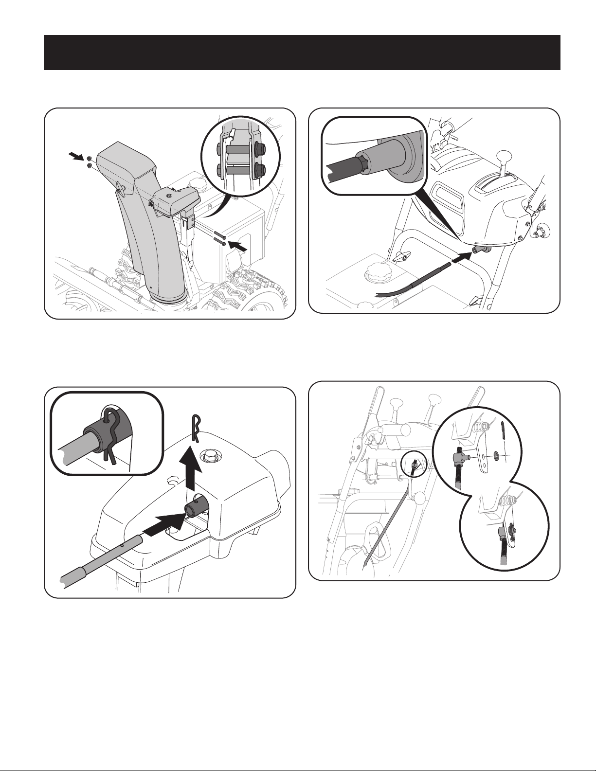
3. Secure chute control head to chute support bracket with lock nuts and hex
screws removed in Step 1. See Figure 28.
Figure 28
NOTE: For smoothest operation, the cables should all be to the left of the chute
control rod.
4. Remove hairpin clip from rear of chute control assembly. See Figure 29.
Figure 29
5. Insert flex shaft removed during handle assembly from lower handle into
rear of chute directional control head. See Figure 29. Secure flex shaft to
chute control head with hairpin clip removed in Step 4.
6. Insert hex end of flex shaft into chute control rod coupling under dash panel.
See Figure 30.
Figure 30
7. Ensure speed selector is in fastest forward speed.
8. Remove cotter pin and washer from ferrule on end of shift rod. See “Figure
31” inset.
Figure 31
Loading ...
Loading ...
Loading ...