Loading ...
Loading ...
Loading ...
65BDL3050Q
4
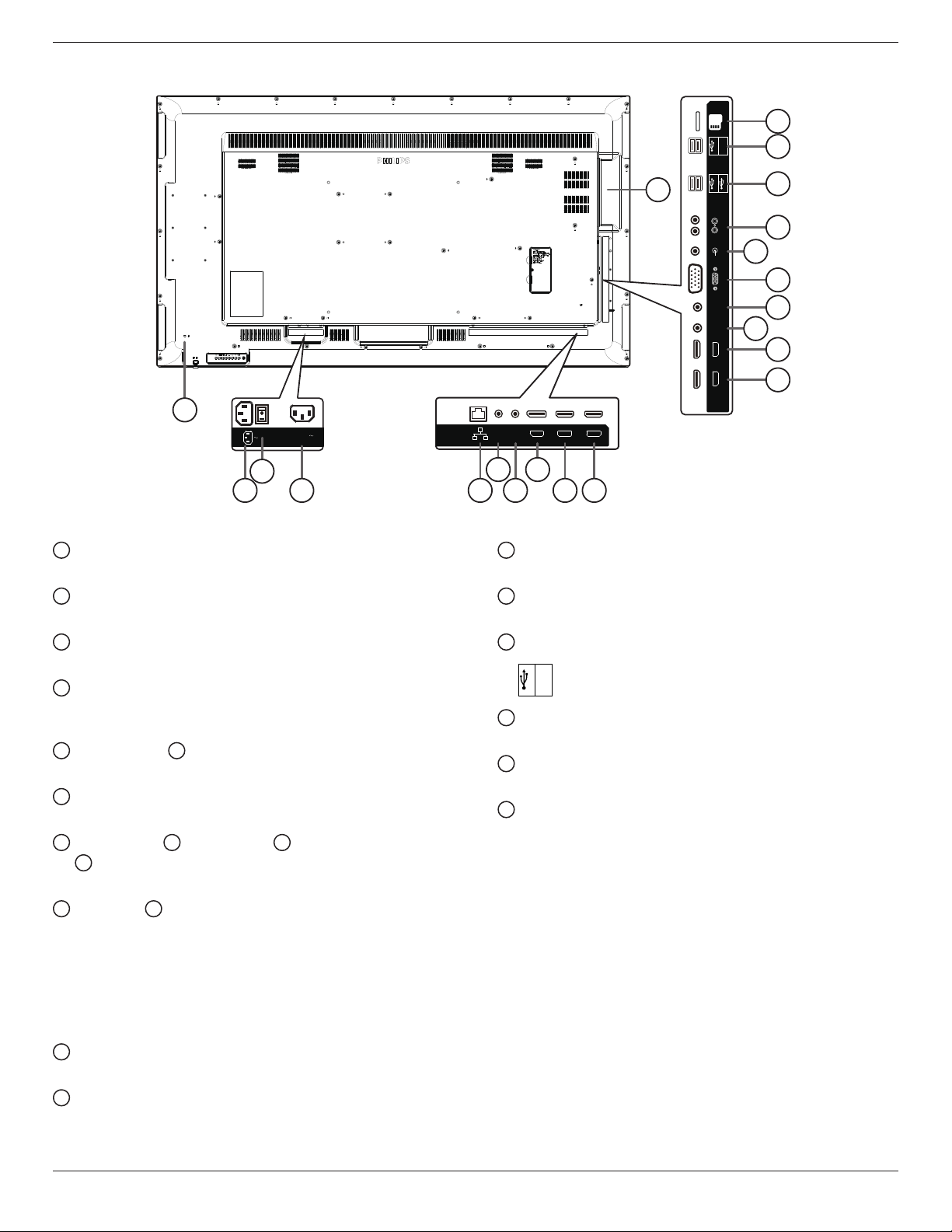
2.2. Input/Output Terminals
HDMI 3 IN HDMI 4 IN
AUDIO IN
MICRO SD
IR-INIR-OUT
AUDIO OUT
USB 5V/0.5A
5V/2A
D-SUB
USB 2.0 5V/0.5A
USB 3.0 5V/0.9A
100-240V
50-60Hz 2.5A
HDMI 1 IN HDMI 2 IN
DP IN
RJ45
RS232
OUT
RS232
IN
10
11
13
12
14
15
17
16
18
19
20
1
21
3
2
4
5 7
6 8 9
1
AC IN
AC power input from the wall outlet.
2
MAIN POWER SWITCH
Switch the main power on/off.
3
AC OUT
AC power supply to the AC IN jack of a media player.
4
RJ-45
LAN control function for the use of remote control signal from
control center.
5
RS232C IN /
6
RS232C OUT
RS232C network input / output for the loop-through function.
7
DisplayPort IN
DisplayPort video input.
8
HDMI1 IN /
9
HDMI2 IN /
10
HDMI3 IN /
11
HDMI4 IN
HDMI video/audio input.
12
IR OUT /
13
IR IN
IR signal input / output for the loop-through function.
NOTES:
• This display’s remote control sensor will stop working if the jack
[IR IN] is connected.
• To remotely control your A/V device via this display, refer to page
14 for or IR Pass Through connection.
14
VGA IN (D-Sub)
VGA video input.
15
AUDIO IN
Audio input for VGA source (3.5mm stereo phone).
16
AUDIO OUT
Audio output to external AV device.
17
USB PORT
Connect your USB storage device
18
USB PORT A
USB
5V/2A
19
MICRO SD CARD
Connect your MICRO SD CARD.
20
OPS SLOT
Slot for installing the optional OPS module.
21
SECURITY LOCK
Used for security and theft prevention.
Loading ...
Loading ...
Loading ...