www.philips.com/welcome
65BDL3050Q
V1.10
User Manual (English)
65BDL3050Q
ii
Safety Instructions
Warnings and Precautions
KNOW THESE SAFETY SYMBOLS
CAUTION: TO REDUCE THE RISK OF ELECTRIC SHOCK, DO NOT
REMOVE COVER (OR BACK). NO USER SERVICEABLE
PARTS INSIDE. REFER SERVICING TO QUALIFIED
SERVICE PERSONNEL.
This symbol indicates high voltage is present inside.
It is dangerous to make any kind of contact with any
inside part of this product.
This symbol alerts you that important literature
concerning operation and maintenance has been
included with this product.
CAUTION: FCC/CSA regulations state that any unauthorized changes
or modications to this equipment may void the user’s
authority to operate it.
CAUTION: To prevent electric shock, match the wide blade of plug to
the wide slot, and fully insert the plug.
TO PREVENT DAMAGE WHICH MAY RESULT IN FIRE OR ELECTRIC
SHOCK HAZARD, DO NOT EXPOSE THIS APPLIANCE TO RAIN OR
MOISTURE.
The Socket-outlet should be installed near the apparatus and be easily
accessible.
Read and follow these instructions
when connecting and using your Public
Information Display:
• Unplug the display if you are not going to use it for an extensive period
of time.
• Unplug the display if you need to clean it with a slightly damp cloth.
The screen many be wiped with a dry cloth when the power is off.
However, never use alcohol, solvents or ammonia-based liquids.
• Consult a service technician if the display does not operate normally
when you have followed the instructions in this manual.
• The casing cover should be opened only by qualied service personnel.
• Keep the display out of direct sunlight and away from stoves or any
other heat sources.
• Remove any object that could fall into the vents or prevent proper
cooling of the display’s electronics.
• Do not block the ventilation holes on the cabinet.
• Keep the display dry. To avoid electric shock, do not expose it to rain
or excessive moisture.
• If turning off the display by detaching the power cable, wait for 6
seconds before re-attaching the power cable for normal operation.
• To avoid the risk of shock or permanent damage to the set do not
expose the display to rain or excessive moisture.
• When positioning the display, make sure the power plug and outlet are
easily accessible.
• IMPORTANT: Always activate a screen saver program during your
application. If a still image in high contrast remains on the screen for an
extended period of time, it may leave an ‘after-image’ or ‘ghost image’
on the front of the screen. This is a well-known phenomenon that is
caused by the shortcomings inherent in LCD technology. In most cases
the afterimage will disappear gradually over a period of time after the
power has been switched off. Be aware that the after-image symptom
cannot be repaired and is not covered under warranty.

65BDL3050Q
iii
Important Safety Instructions
1. Read these instructions.
2. Keep these instructions.
3. Heed all warnings.
4. Follow all instructions.
5. Do not use this apparatus near water.
6. Clean only with dry cloth.
7. Do not block any ventilation openings. Install in accordance with the
manufacturer’s instructions.
8. Do not install near any heat sources such as radiators, heat registers,
stoves, or other apparatus (including ampliers) that produce heat.
9. Do not defeat the safety purpose of the polarized or grounding-type
plug. A polarized plug has two blades with one wider than the other.
A grounding type plug has two blades and a third grounding prong.
The wide blade or the third prong are provided for your safety. If the
provided plug does not t into your outlet, consult an electrician for
replacement of the obsolete outlet.
10. Protect the power cord from being walked on or pinched particularly
at plugs, convenience receptacles, and the point where they exit from
the apparatus.
11. Only use attachments/accessories specied by the manufacturer.
12. Use only with the cart, stand, tripod, bracket, or
table specied by the manufacturer, or sold with the
apparatus. When a cart is used, use caution when
moving the cart/apparatus combination to avoid
injury from tip-over.
13. Unplug this apparatus during lightning storms or when unused for long
periods of time.
14. Refer all servicing to qualied service personnel. Servicing is required
when the apparatus has been damaged in any way, such as power-
supply cord or plug is damaged, liquid has been spilled or objects have
fallen into the apparatus, the apparatus has been exposed to rain or
moisture, does not operate normally, or has been dropped.
15. The batteries (batteries installed) shall not be exposed to excessive
heat such as sunshine, re or the like.
16. An all-pole MAINS SWITCH is used as the disconnect device, the
location on the apparatus and the function of the switch shall be
described, and the switch shall remain readily operable
WARNING: TO REDUCE THE RISK OF FIRE OR ELECTRIC SHOCK,
DO NOT EXPOSE THIS APPARATUS TO RAIN OR
MOISTURE.
WARNING: Apparatus shall not be exposed to dripping or splashing
and no objects lled with liquids, such as vases, shall be
placed on the apparatus.
WARNING: The batteries (batteries installed) shall not be exposed to
excessive heat such as sunshine, re or the like.
WARNING: The mains plug or appliance coupler is used as the
disconnect device,the disconnect device shall remain
readily operable.
WARNING: To prevent the spread of re, keep candles or other open
ames away from this product at all times.
WARNING: To prevent injury, this apparatus must be securely attached
to the oor/wall in accordance with the installation
instructions.
WARNING: The Class I apparatus shall be connected to a mains socket
outlet with a protective earthing connection.
WARNING
Never place a television set in an unstable location. A television set may
fall, causing serious personal injury or death. Many injuries, particularly to
children, can be avoided by taking simple precautions such as:
• Using cabinets or stands recommended by the manufacturer of the
television set.
• Only using furniture that can safely support the television set.
• Ensuring the television set is not overhanging the edge of the
supporting furniture.
• Not placing the television set on tall furniture (for example, cupboards
or bookcases) without anchoring both the furniture and the television
set to a suitable support.
• Not placing the television set on cloth or other materials that may be
located between the television set and supporting furniture.
• Educating children about the dangers of climbing on furniture to reach
the television set or its controls.
If your existing television set is being retained and relocated, the same
considerations as above should be applied.
CAUTION: These servicing instructions are for use by qualied service
personnel only. To reduce the risk of electric shock,do not
perform any servicing other than that contained in the
operating instructions unless you are qualitied to do so.
CAUTION: Excessive sound pressure from earphones and headphones
can cause hearing loss. Adjustment of the equalizer to
maximum increases the earphone and headphone output
voltage and the sound pressure level. Therefore, to protect
your hearing, adjust the equalizer to an appropriate level.
For UL/CUL application: For use only with UL Listed Wall Mount Bracket
with minimum weight/load: 24.8 Kg
For CB application: Unit without base weight: 24.8 Kg. The equipment and
its associated mounting means still remain secure during the test.(Used
wall mounting kit: 400x400 mm distance by using M6 screws of 10 mm
long plus the thickness of the mounting bracket.
65BDL3050Q
iv
IMPORTANT INFORMATION
Ifatelevisionisnotpositionedinasufcientlystablelocation,itcanbe
potentiallyhazardousduetofalling.Manyinjuries,particularlytochildren,
canbeavoidedbytakingsimpleprecautionssuchas:
• Using cabinets or stands recommended by the manufacturer of the
television.
• Only using furniture that can safely support the television.
• Ensuring the television is not overhanging the edge of the supporting
furniture.
• Not placing the television on tall furniture(for example, cupboards or
bookcases)without anchoring both the furniture and the television to a
suitable support.
• Not standing the televisions on cloth or other materials placed
between the television and supporting furniture.
• Educating children about the dangers of climbing on furniture to reach
the television or its controls.
EU Declaration of Conformity
This device complies with the requirements set out in the Council
Directive on the Approximation of the Laws of the Member States relating
to Electromagnetic Compatibility (2014/30/EU), Low-voltage Directive
(2014/35/EU) and RoHS directive (2011/65/EU).
This product has been tested and found to comply with the harmonized
standards for Information Technology Equipment, these harmonized
standards published under Directives of Ofcial Journal of the European
Union.
Warning:
This equipment is compliant with Class A of EN55032/CISPR 32. In a
residential environment this equipment may cause radio interference.
ESD Warnings
When user close to the monitor may cause the equipment discharge and
reboot to the display of main menu.
InformationforEAC
Monthandyearof
manufacturing
pleasereferinformationinRatinglabel.
Nameandlocationof
manufacturer
ООО“Профтехника”
Адрес:3-йПроездМарьинойрощи,
40/1офис1.Москва,127018,Россия
Importerandinformation Наименованиеорганизации:ООО
“Профтехника”
Адрес:3-йПроездМарьинойрощи,
40/1офис1.Москва,127018,Россия
Контактноелицо:НатальяАстафьева,
+74956402020
nat@profdisplays.ru
Federal Communications Commission (FCC)
Notice (U.S. Only)
Note: This equipment has been tested and found to
comply with the limits for a Class A digital
device, pursuant to part 15 of the FCC Rules. These
limits are designed to provide reasonable
protection against harmful interference when the
equipment is operated in a commercial
environment. This equipment generates, uses, and can
radiate radio frequency energy and, if not installed and
used in accordance with the instruction manual, may
cause harmful interference to radio communications.
Operation of this equipment in a residential area is
likely to cause harmful interference in which case the
user will be required to correct the interference at his
own expense.
Changes or modications not expressly approved by
the party responsible for compliance could void the
user’s authority to operate the equipment.
Use only an RF shielded cable that was supplied with the display when
connecting this display to a computer device.
To prevent damage which may result in re or shock hazard, do not
expose this appliance to rain or excessive moisture.
This device complies with Part 15 of the FCC Rules. Operation is subject
to the following two conditions: (1) this device may not cause harmful
interference, and (2) this device must accept any interference received,
including interference that may cause undesired operation.
Envision Peripherals Inc.
47409 Seabridge Drive
Fremont, CA 94538
Tel. 510-770-9988
Polish Center for Testing and Certication
Notice
The equipment should draw power from a socket with an attached
protection circuit (a three-prong socket). All equipment that works
together (computer, display, printer, and so on) should have the same
power supply source.
The phasing conductor of the room’s electrical installation should have a
reserve short-circuit protection device in the form of a fuse with a nominal
value no larger than 16 amperes (A).
To completely switch off the equipment, the power supply cable must be
removed from the power supply socket, which should be located near the
equipment and easily accessible.
A protection mark “B” conrms that the equipment is in compliance with
the protection usage requirements of standards PN-93/T-42107 and PN-
89/E-06251.
65BDL3050Q
v
Electric, Magnetic and Electronmagnetic Fields
(“EMF”)
1. We manufacture and sell many products targeted at consumers, which,
like any electronic apparatus, in general have the ability to emit and
receive electromagnetic signals.
2. One of our leading Business Principles is to take all necessary health
and safety measures for our products, to comply with all applicable
legal requirements and to stay well within the EMF standards applicable
at the time of producing the products.
3. We are committed to develop, produce and market products that
cause no adverse health effects.
4. We conrm that if its products are handled properly for their intended
use, they are safe to use according to scientic evidence available today.
5. We play an active role in the development of international EMF and
safety standards, enabling us to anticipate further developments in
standardization for early integration in its products.
Information for U.K. only
WARNING – THIS APPLIANCE MUST BE EARTHED.
Important:
(A)
(B)
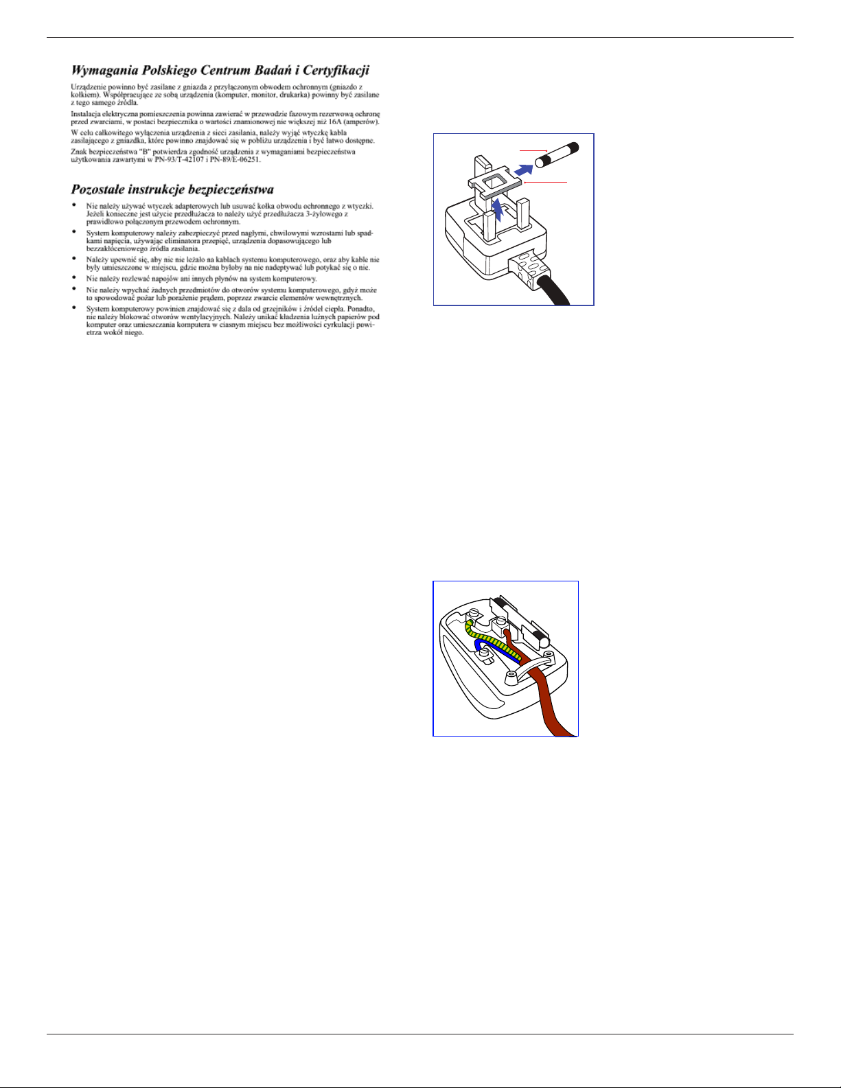
This apparatus is supplied with an approved moulded 13A plug. To change
a fuse in this type of plug proceed as follows:
1. Remove fuse cover and fuse.
2. Fit new fuse which should be a BS 1362 5A,A.S.T.A. or BSI approved
type.
3. Ret the fuse cover.
If the tted plug is not suitable for your socket outlets, it should be cut off
and an appropriate 3-pin plug tted in its place.
If the mains plug contains a fuse, this should have a value of 5A. If a plug
without a fuse is used, the fuse at the distribution board should not be
greater than 5A.
NOTE: The severed plug must be destroyed to avoid a possible shock
hazard should it be inserted into a 13A socket elsewhere.
How to connect a plug
The wires in the mains lead are coloured in accordance with the following
code:
BLUE – “NEUTRAL” (“N”)
BROWN – “LIVE” (“L”)
GREEN & YELLOW – “EARTH” (“E”)
1. The GREEN & YELLOW wire must be connected to the terminal in
the plug which is marked with the letter “E” or by the Earth symbol or
coloured GREEN or GREEN & YELLOW.
2. The BLUE wire must be connected to the terminal which is marked
with the letter “N” or coloured BLACK.
3. The BROWN wire must be connected to the terminal which marked
with the letter “L” or coloured RED.
Before replacing the plug cover, make certain that the cord grip is clamped
over the sheath of the lead – not simply over the three wires.
65BDL3050Q
vi
China RoHS
根据中国大陆《电子电气产品有害物质限制使用标识要求》,以下部分
列出了本产品中可能包含的有害物质的名称和含量。
零部件名称
有害物质
铅
(Pb)
汞
(Hg)
镉
(Cd)
六价铬
(Cr
(VI))
多溴
联苯
(PBB)
多溴二
苯醚
(PBDE)
外壳 ○ ○ ○ ○ ○ ○
液晶显示屏 × ○ ○ ○ ○ ○
电路板组件* × ○ ○ ○ ○ ○
电源适配器 × ○ ○ ○ ○ ○
电源线/连接线 × ○ ○ ○ ○ ○
遥控器 X ○ ○ ○ ○ ○
本表格依据SJ/T 11364 的规定编制。
*: 电路板组件包括印刷电路板及其构成的零部件,如电阻、
电容、集成电路、连接器等。
O: 表示该有害物质在该部件所有均质材料中的含量均在
GB/T 26572规定的限量要求以下。
X: 表示该有害物质至少在该部件的某一均质材料中的含量超
出GB/T 26572规定的限量要求。
上表中打“×”的部件,应功能需要,部分有害物质含量超出
GB/T 26572规定的限量要求,但符合欧盟RoHS法规要求(属于
豁免部分)。
备注:上表仅做为范例,实际标示时应依照各产品的实际部件及所
含有害物质进行标示。
10
环保使用期限
在产品本体上标示的该标志表示环境保护使用期限为
10
年。
电子信息产品的环境保护使用期限是指电子信息产品中所含的有害
物质不会向外部泄漏或出现突然变异,并且电子信息产品的用户在
使用该电子信息产品时也不会对环境造成严重污染或对人体、财产
带来严重损害的期限。
在环境保护期限中,请按照使用说明书使用本产品。
本环境保护使用不覆盖易损件:电池。
《废弃电子产品回收处理管理条例》提示性说明
为了更好地关爱及保护地球,当用户不再需要此产品或产品寿命终
止时,请遵守国家废弃电器电子产品回收处理相关法律规定,将其
交给当地具有国家认可的回收处理资质的厂商进行回收处理。
警告
此为 A 级产品。在生活环境中,该产品可能会造成无线电干扰。
在这种情况下,可能需要用户对干扰采取切实可行的措施。
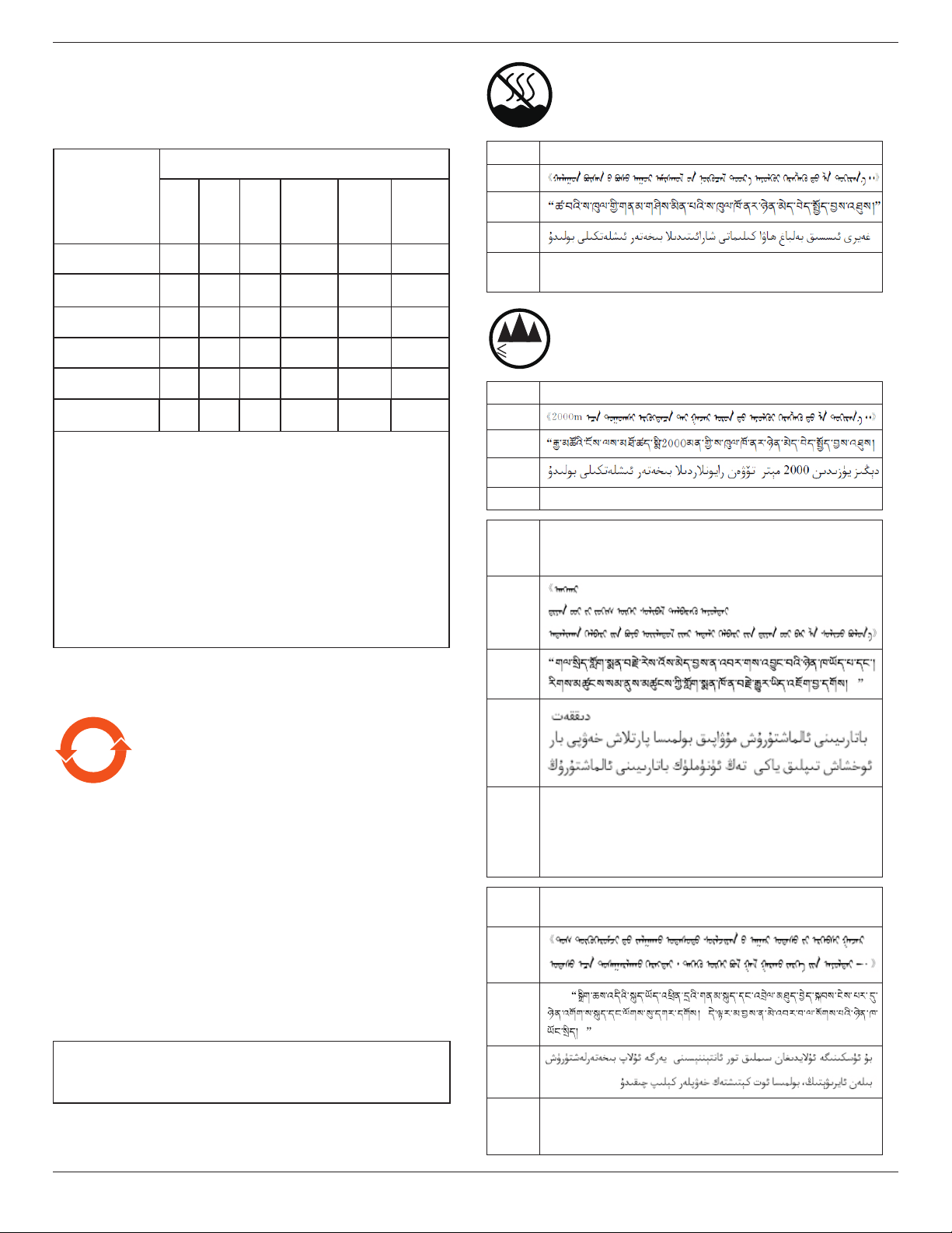
仅适用于非热带气候条件下安全使用 :
汉文仅适用于非热带气候条件下安全使用。
蒙古文
藏文
维文
壮文
Dan hab yungh youq gij dienheiq diuzgen mbouj dwg
diegndat haenx ancienz sawjyungh.
≤200
0
m
仅适用于海拔 2000m 以下地区安全使用 :
汉文仅适用于海拔 2000m 以下地区安全使用。
蒙古文
藏文
维文
壮文Hai dou gaxgonq, wngdang sien duenh denvasen bae.
汉文
“注意
如果电池更换不当会有爆炸危险
只能用同样类型或等效类型的电池来更换”
蒙古文
藏文
维文
壮文
“Louzsim
Danghnaeuz denyouz vuenh ndaej mbouj habdangq aiq miz
gij yungyiemj fatseng bauqcaq
Cijndaej yungh gij denyouz doengzyiengh loihhingz roxnaeuz
daengjyauq loihl haenx vuenh”
汉文
“接入本设备的有线网络天线必须与保护接地隔离 , 不
然可能会引起着火等危险 !”
蒙古文
藏文
维文
壮文
“Gij mizsienq vangjloz denhsen ciephaeuj bonj sezbi daeuj
haenx itdingh aeu caeuq gij ciepdieg baujhoh doxliz, mboujne
aiq miz gij yungyiemj dawzfeiz daengj!”
65BDL3050Q
vii
North Europe (Nordic Countries) Information
Placering/Ventilation
VARNING:
FÖRSÄKRA DIG OM ATT HUVUDBRYTARE OCH UTTAG
ÄR LÄTÅTKOMLIGA, NÄR DU STÄLLER DIN UTRUSTNING
PÅPLATS.
Placering/Ventilation
ADVARSEL:
SØRG VED PLACERINGEN FOR, AT NETLEDNINGENS STIK OG
STIKKONTAKT ER NEMT TILGÆNGELIGE.
Paikka/Ilmankierto
VAROITUS:
SIJOITA LAITE SITEN, ETTÄ VERKKOJOHTO VOIDAAN
TARVITTAESSA HELPOSTI IRROTTAA PISTORASIASTA.
Plassering/Ventilasjon
ADVARSEL:
NÅR DETTE UTSTYRET PLASSERES, MÅ DU PASSE PÅ AT
KONTAKTENE FOR STØMTILFØRSEL ER LETTE Å NÅ.
End-of-Life Disposal
Your new Public Information Display contains materials that can be
recycled and reused. Specialized companies can recycle your product to
increase the amount of reusable materials and to minimize the amount to
be disposed of.
Please nd out about the local regulations on how to dispose of your old
display from your local philips dealer.
(For customers in Canada and U.S.A.)
This product may contain lead and/or mercury. Dispose of in accordance
to local-state and federal regulations. For additional information on
recycling contact www.eia.org (Consumer Education Initiative)
Waste Electrical and Electronie Equipment-
WEEE
Attention users in European Union private households
This marking on the product or on its packaging
illustrates that, under European Directive 2012/19/
EU governing used electrical and electronic appliances,
this product may not be disposed of with normal
household waste. You are responsible for disposal of
this equipment through a designated waste electrical
and electronic equipment collection. To determine
the locations for dropping off such waste electrical
and electronic, contact your local government ofce,
the waste disposal organization that serves your
household or the store at which you purchased the
product.
End of Life Directives-Recycling
Your new Public Information Display contains several
materials that can be recycled for new users.
Please dispose of according to all Local, State, and
Federal laws.
As an ENERGY STAR Partner, we have determined
that this product meets the ENERGY STAR guidelines
for energy efciency.
Restriction on Hazardous Substances statement (India)
This product complies with the “E-Waste (Management) Rules, 2016”
CHAPTER V, rule 16, sub-rule (1) . Whereas New Electrical and
Electronic Equipment and their components or consumables or parts or
spares do not contain Lead, Mercury, Cadmium, Hexavalent Chromium,
polybrominated biphenyls and polybrominated diphenyl ethers beyond a
maximum concentration value of 0.1% by weight in homogenous materials
for lead, mercury, hexavalent chromium, polybrominated biphenyls and
polybrominated diphenyl ethers and of 0.01% by weight in homogenous
materials for cadmium. except of exemptions set in Schedule 2 of the Rule.
E-Waste Declaration for India
This symbol on the product or on its packaging
indicates that this product must not be disposed of
with your other household waste. Instead it is your
responsibility to dispose of your waste equipment
by handing it over to a designated collection point
for the recycling of waste electrical and electronic
equipment . The separate collection and recycling
of your waste equipment at the time of disposal
will help to conserve natural resources and ensure
that it is recycled in a manner that protects human
health and the environment. For more information
about E -waste please visit http://www.india.philips.
com/about/sustainability/recycling/index.page
and to know where you can drop off your waste
equipment for recycling in India please contact on
below given contact details.
65BDL3050Q
viii
Helpline number: 1800-425-6396 (Monday to Saturday, 9 a.m. to 5:30 pm)
Centralized E-waste collection center
Address: TPV Technology India Private Limited,
59, Maheswari Nagar, 1st Main Road, Mahadevapura Post,
Whiteeld Road
Bangalore, Karnataka, PIN: 560048, Tel: 080-3023-1000
E-mail: [email protected]
Batteries
ForEU:Thecrossed-outwheeledbinimplies
thatusedbatteriesshouldnotbeputtothe
generalhouseholdwaste!Thereisaseparate
collectionsystemforusedbatteries,toallow
propertreatmentandrecyclinginaccordancewith
legislation.
Pleasecontactyourlocalauthorityfordetailson
thecollectionandrecyclingschemes.
ForSwitzerland:Theusedbatteryistobereturned
to the selling point.
Forothernon-EUcountries:Pleasecontactyour
localauthorityforcorrectmethodofdisposalof
theusedbattery.
AccordingtoEUdirective2006/66/EC,thebattery
can’tbedisposedimproperly.Thebatteryshallbe
separatedtocollectbylocalservice.
Após o uso, as pilhas
deverão ser entregues ao
estabelecimento comercial
ou
e/ou baterias
rede de assistência técnica
autorizada.
Turkey RoHS:
Türkiye Cumhuriyeti: EEE Yönetmeliğine Uygundur
Ukraine RoHS:
Обладнання відповідає вимогам Технічного регламенту щодо
обмеження використання деяких небезпечних речовин в електричному
та електронному обладнанні, затвердженого постановою Кабінету
Міністрів України від 3 грудня 2008 № 1057

65BDL3050Q
ix
Table Of Contents
1. UnpackingandInstallation .......................................................1
1.1. Unpacking .........................................................................................1
1.2. Package Contents ........................................................................ 1
1.3. Installation Notes .........................................................................1
1.4. Mounting on a Wall ....................................................................2
2. PartsandFunctions ...................................................................3
2.1. Control Panel ................................................................................. 3
2.2. Input/Output Terminals .............................................................4
2.3. Remote Control ........................................................................... 6
3. ConnectingExternalEquipment.......................................... 10
3.1. Connecting External Equipment (DVD/VCR/
VCD) ...............................................................................................10
3.2. Connecting a PC ....................................................................... 10
3.3. Connecting Audio Equipment ...........................................11
3.4. Connecting Multiple Displays in a Daisy-chain
Conguration .............................................................................. 11
3.5. IR connection .............................................................................. 12
3.6. IR Pass-through Connection ...............................................13
4. Operation ................................................................................. 14
4.1. Watch the Connected Video Source ............................14
4.2. Change Picture Format ......................................................... 14
4.3. Overview.......................................................................................14
4.4. Media Player introduction: ...................................................15
4.5. Browser manual .........................................................................17
4.6. PDF reader play .........................................................................20
4.7. CMND & Play .............................................................................22
4.8. Custom App ................................................................................22
5. Signagedisplay ......................................................................... 24
5.1. Setting ..............................................................................................24
5.2. Wi-Fi ................................................................................................24
5.3. Ethernet..........................................................................................24
5.4. Proxy ................................................................................................25
5.5. Signage Display ...........................................................................25
5.6. System Tools ................................................................................33
5.7. Clone Media File .......................................................................34
5.8. Display ...........................................................................................35
5.9. Apps .................................................................................................35
5.10. Security ........................................................................................... 35
5.11. Date & time .................................................................................35
5.12. Developer options ................................................................... 35
5.13. About ..............................................................................................36
5.14. Supplementary ........................................................................... 36
6. OSD Menu ............................................................................... 39
6.1. Navigating the OSD Menu ..................................................39
6.2. OSD Menu Overview ...........................................................39
7. SupportedMediaFormats .................................................... 45
8. InputMode ............................................................................... 47
9. PixelDefectPolicy .................................................................. 48
9.1. Pixels and Sub-Pixels ...............................................................48
9.2. Types of Pixel Defects + Dot Denition ....................48
9.3. Bright Dot Defects ...................................................................48
9.4. Dark Dot Defects.....................................................................49
9.5. Proximity of Pixel Defects ................................................... 49
9.6. Pixel Defect Tolerances .........................................................49
9.7. MURA .............................................................................................49
10. CleaningandTroubleshooting .............................................. 50
10.1. Cleaning ..........................................................................................50
10.2. Troubleshooting .........................................................................51
11. TechnicalSpecications ......................................................... 53
65BDL3050Q
1
1. Unpacking and Installation
1.1. Unpacking
• This product is packed in a carton, together with the standard accessories.
• Any other optional accessories will be packed separately.
• Due to the size and weight of this display it is recommended for two people to move it.
• After opening the carton, ensure that the contents are complete and in good condition.
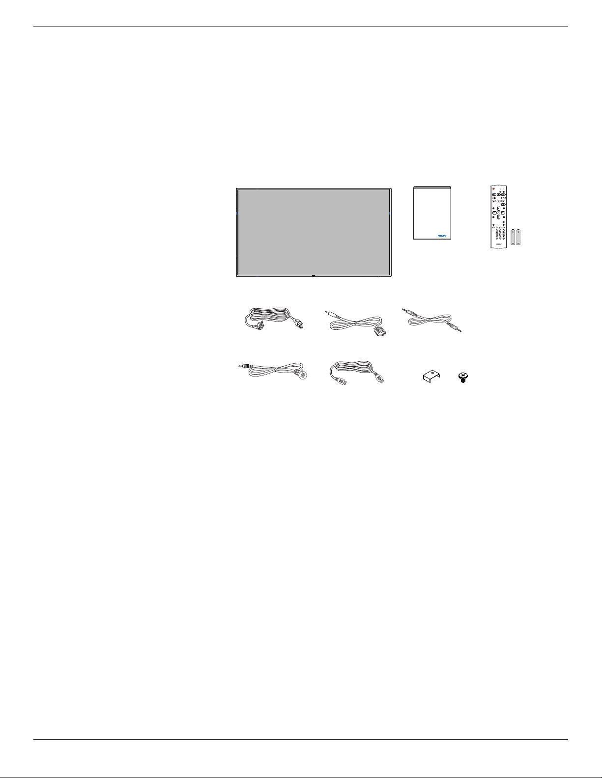
1.2. Package Contents
Please verify that you received the following items with your package content:
• LCD display
• Quick start guide
• Remote control with AAA batteries
• Power cord
• RS232 cable
• RS232 daisy chain cable
• IR sensor cable
• HDMI cable
• USB cover and screw x1
* The supplied power cord varies depending on destination.
Power Cord
Quick start guide
Remote Control
and AAA Batteries
RS232 Daisy Chain Cable
FORMAT
SOURCE
INFOLIST
OPTIONSADJUST
VOL
NORMAL
ID
ID SET ENTER
RS232 Cable
HDMI Cable USB Cover x1IR Sensor Cable
* Differences according to regions
Display design and accessories may differ from those illustrated above.
NOTES:
• For all other regions, apply a power cord that conforms to the AC voltage of the power socket and has been approved by and complies with the
safety regulations of the particular country (Type H05W-F, 2G or 3G, 0.75 or 1 mm
2
should be used).
• You might like to save the package box and packing material for shipping the display.
1.3. Installation Notes
• Due to the high power consumption, always use the plug exclusively designed for this product. If an extended line is required, please consult your
service agent.
• The product should be installed on a at surface to avoid tipping. The distance between the back of the product and the wall should be maintained
for proper ventilation. Avoid installing the product in the kitchen, bathroom or any other places with high humidity so as not to shorten the service life
of the electronic components.
• The product can normally operate only under 3000m in altitude. In installations at altitudes above 3000m, some abnormalities may be experienced.
65BDL3050Q
2
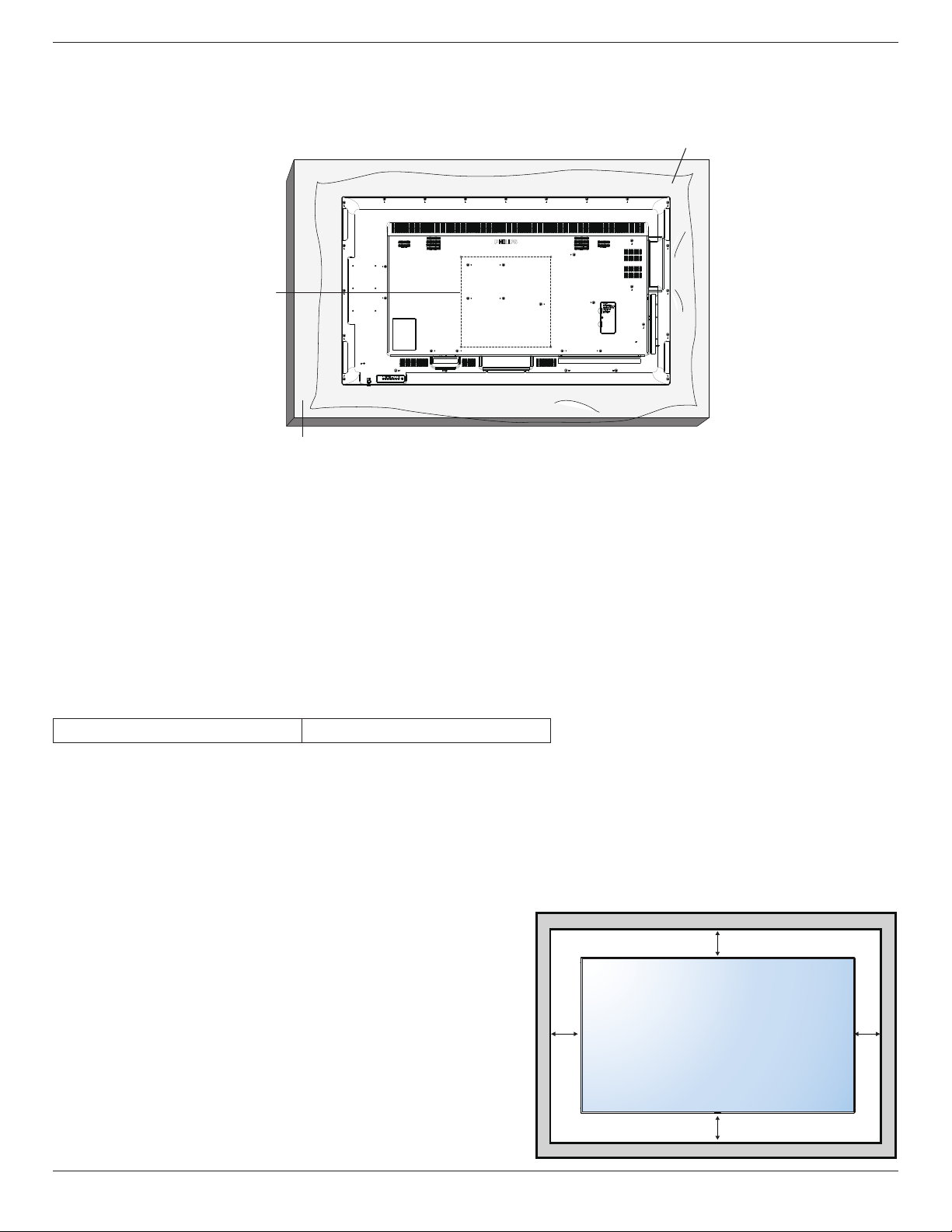
1.4. Mounting on a Wall
To mount this display to a wall, you will have to obtain a standard wall-mounting kit (commercially available). We recommend using a mounting interface
that complies with TUV-GS and/or UL1678 standard in North America.
Protective Sheet
VESA Grid
Table
1. Lay a protective sheet on a table, which was wrapped around the display when it was packaged, beneath the screen surface so as not to scratch the
screen face.
2. Ensure you have all accessories for mounting this display (wall mount, ceiling mount, table stand, etc).
3. Follow the instructions that come with the base mounting kit. Failure to follow correct mounting procedures could result in damage to the equipment
or injury to the user or installer. Product warranty does not cover damage caused by improper installation.
4. For the wall-mounting kit, use M6 mounting screws (having a length 10 mm longer than the thickness of the mounting bracket) and tighten them
securely.
5. Unit without base weight= 24.8 kg. The equipment and its associated mounting means still remain secure during the test. For use only with UL Listed
Wall Mount Bracket with minimum weight/load: 24.8 kg.
6. Portrait is not allowed.
1.4.1. VESA Grid
65BDL3050Q
400(H) x 400(V) mm
Caution:
To prevent the display from falling:
• For wall or ceiling installation, we recommend installing the display with metal brackets which are commercially available. For detailed installation
instructions, refer to the guide received with the respective bracket.
• To lessen the probability of injury and damage resulting from fall of the display in case of earthquake or other natural disaster, be sure to consult the
bracket manufacturer for installation location.
Ventilation Requirements for enclosure locating
To allow heat to disperse, leave space between surrounding objects as shown in the
diagram below.
100 mm 100 mm
100 mm
100 mm
65BDL3050Q
3
2. Parts and Functions
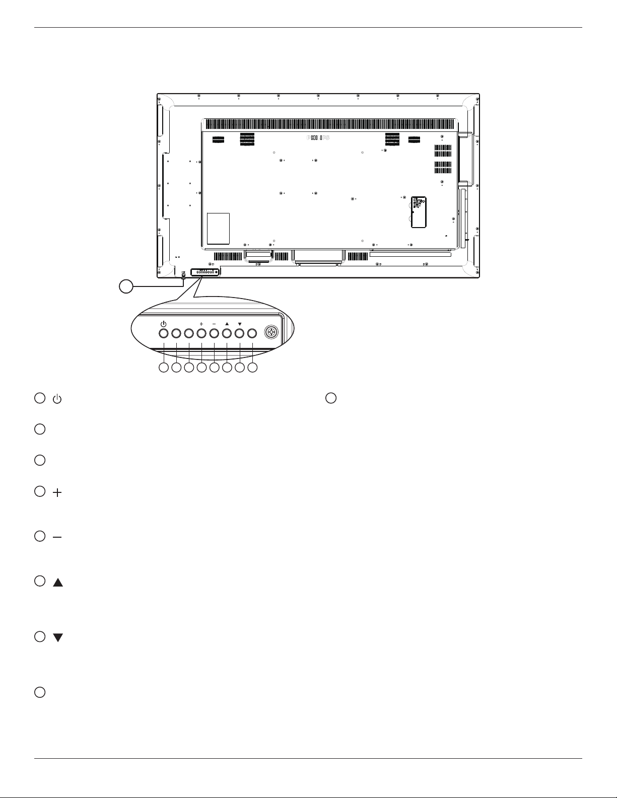
2.1. Control Panel
MUTE INPUT
MENU
1 2 3 4 5 6 7 8
9
1
[ ] button
Use this button to turn the display on or put the display to standby.
2
[MUTE] button
Switch the audio mute ON/OFF.
3
[INPUT] button
Choose the input source.
4
[ ] button
• Increase the volume
• Enter into submenu while OSD menu is on
5
[ ] button
• Decrease the volume
• Back to previous menu while OSD menu is on
6
[ ] button
• Move the highlight bar up to adjust the selected item while
OSD menu is on
• Increase the adjustment while adjust value.
7
[ ] button
• Move the highlight bar down to adjust the selected item while
OSD menu is on.
• Decrease the adjustment while adjust value.
8
[MENU] button
Return to previous menu while OSD menu is on, or to activate the
OSD menu when OSD menu is off.
9
Remote control sensor and power status indicator
• Receives command signals from the remote control.
• Indicates the operating status of the display without OPS:
- Lights green when the display is turned on
- Lights red when the display is in standby mode
- When {SCHEDULE} is enabled, the light blinks green and red
- If the light blinks red, it indicates that a failure has been
detected
- Lights off when the main power of the display is turned off
*UsingIRsensorcableforbetterremotecontrolperformance.
(Please refer to the instructions of 3.5)
65BDL3050Q
4
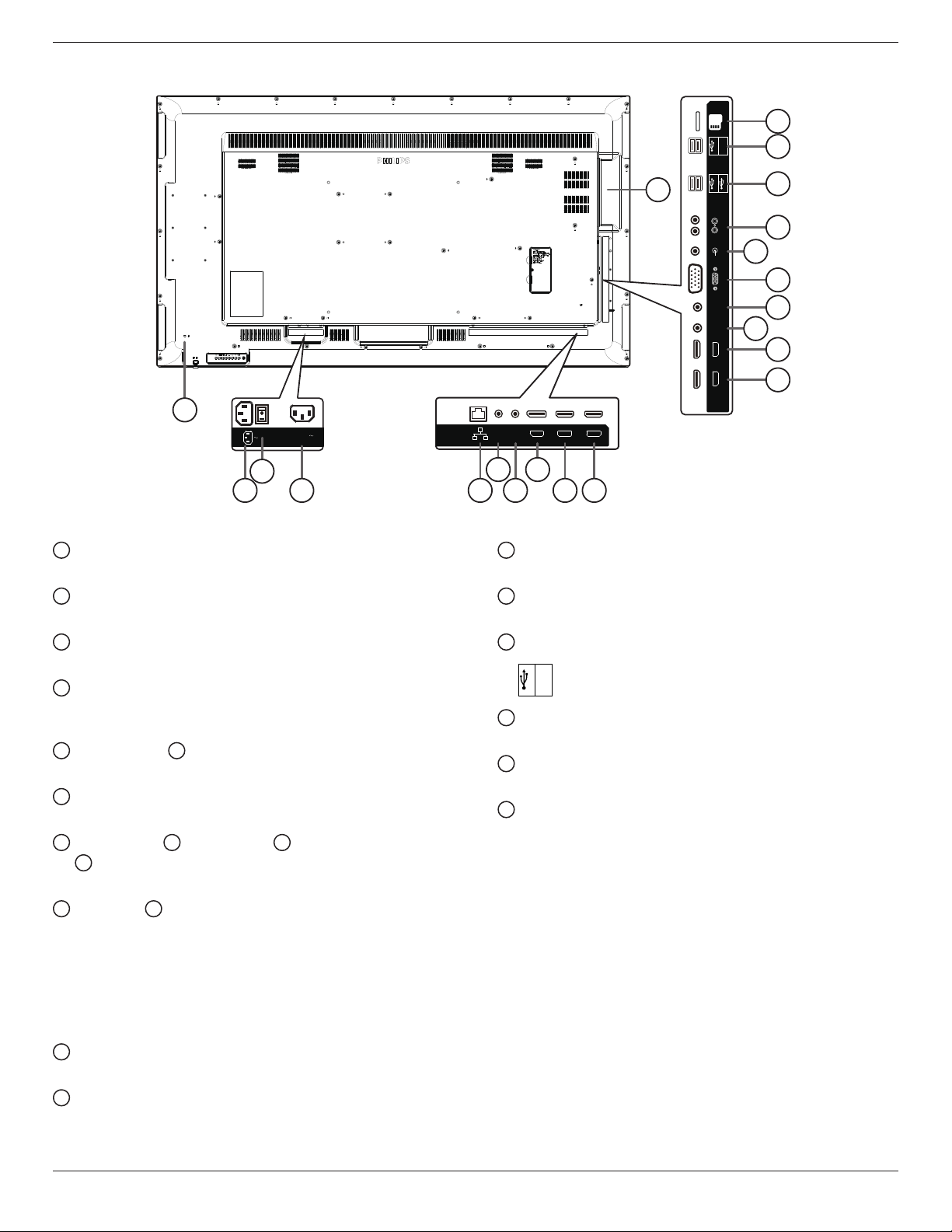
2.2. Input/Output Terminals
HDMI 3 IN HDMI 4 IN
AUDIO IN
MICRO SD
IR-INIR-OUT
AUDIO OUT
USB 5V/0.5A
5V/2A
D-SUB
USB 2.0 5V/0.5A
USB 3.0 5V/0.9A
100-240V
50-60Hz 2.5A
HDMI 1 IN HDMI 2 IN
DP IN
RJ45
RS232
OUT
RS232
IN
10
11
13
12
14
15
17
16
18
19
20
1
21
3
2
4
5 7
6 8 9
1
AC IN
AC power input from the wall outlet.
2
MAIN POWER SWITCH
Switch the main power on/off.
3
AC OUT
AC power supply to the AC IN jack of a media player.
4
RJ-45
LAN control function for the use of remote control signal from
control center.
5
RS232C IN /
6
RS232C OUT
RS232C network input / output for the loop-through function.
7
DisplayPort IN
DisplayPort video input.
8
HDMI1 IN /
9
HDMI2 IN /
10
HDMI3 IN /
11
HDMI4 IN
HDMI video/audio input.
12
IR OUT /
13
IR IN
IR signal input / output for the loop-through function.
NOTES:
• This display’s remote control sensor will stop working if the jack
[IR IN] is connected.
• To remotely control your A/V device via this display, refer to page
14 for or IR Pass Through connection.
14
VGA IN (D-Sub)
VGA video input.
15
AUDIO IN
Audio input for VGA source (3.5mm stereo phone).
16
AUDIO OUT
Audio output to external AV device.
17
USB PORT
Connect your USB storage device
18
USB PORT A
USB
5V/2A
19
MICRO SD CARD
Connect your MICRO SD CARD.
20
OPS SLOT
Slot for installing the optional OPS module.
21
SECURITY LOCK
Used for security and theft prevention.
65BDL3050Q
5
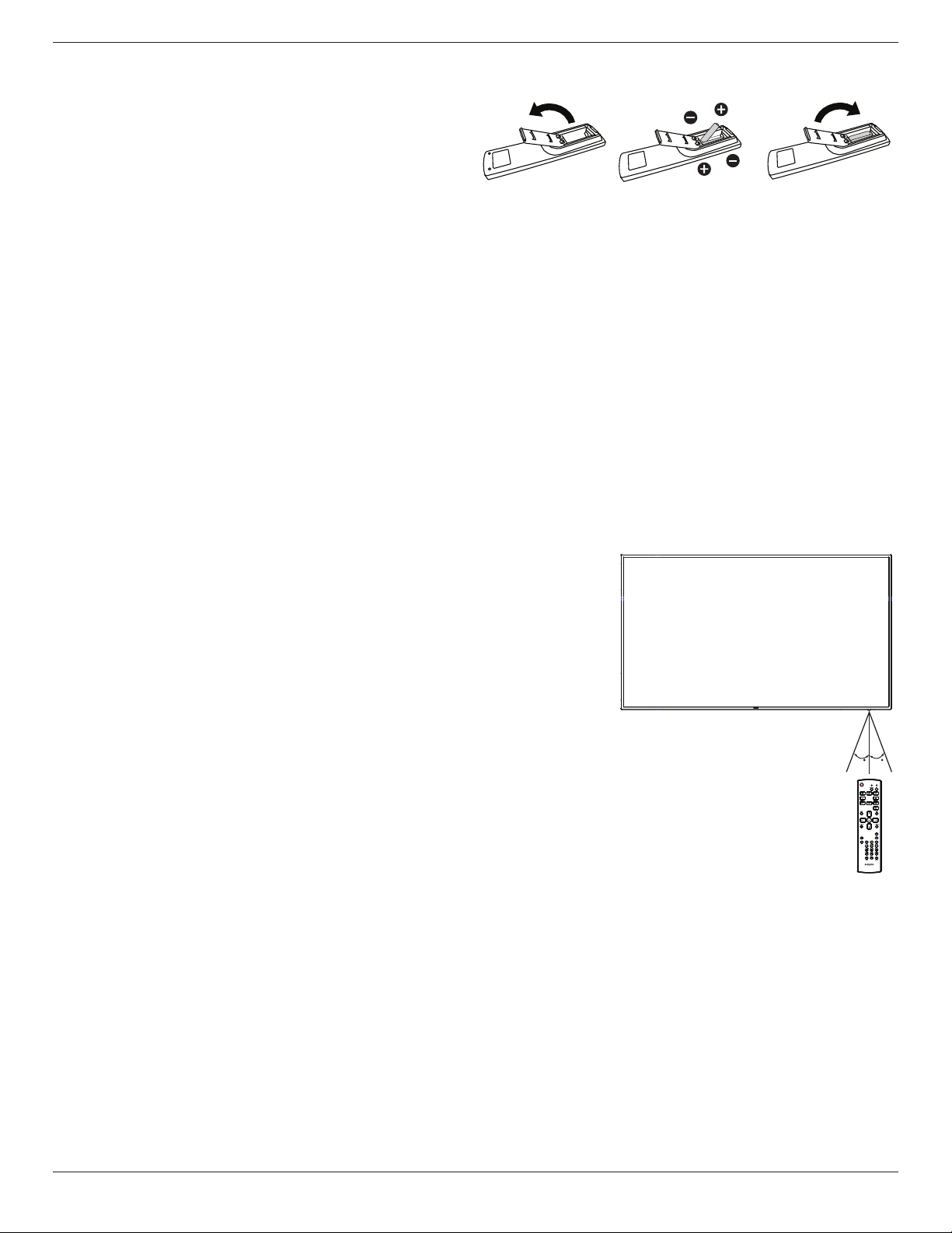
2.2.1. Inserting the batteries in the remote control
The remote control is powered by two 1.5V AAA batteries.
To install or replace batteries:
1. Press and then slide the cover to open it.
2. Align the batteries according to the (+) and (–) indications inside the
battery compartment.
3. Replace the cover.
Caution:
The incorrect use of batteries can result in leaks or bursting. Be sure to follow these instructions:
• Place “AAA” batteries matching the (+) and (–) signs on each battery to the (+) and (–) signs of the battery compartment.
• Do not mix battery types.
• Do not combine new batteries with used ones. It causes shorter life or leakage of batteries.
• Remove the dead batteries immediately to prevent them from liquid leaking in the battery compartment. Don’t touch exposed battery acid, as it can
damage your skin.
NOTE: If you do not intend to use the remote control for a long period, remove the batteries.
2.2.2. Handling the remote control
• Do not subject to strong shock.
• Do not allow water or other liquid to splash the remote control. If the remote control gets wet, wipe it dry immediately.
• Avoid exposure to heat and steam.
• Other than to install the batteries, do not open the remote control.
2.2.3. Operating range of the remote control
Point the top of the remote control toward the display’s remote control sensor when pressing a
button.
Use the remote control within a distance of less than 5m/16ft from the display’s sensor, and a
horizontal and vertical angle of less than 30 degrees.
NOTE: The remote control may not function properly when the remote control sensor on the
display is under direct sunlight or strong illumination, or when there is an obstacle in the
path of signal transmission.
3030
65BDL3050Q
6
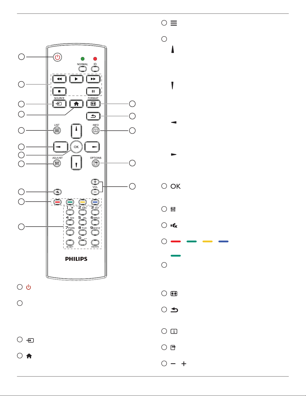
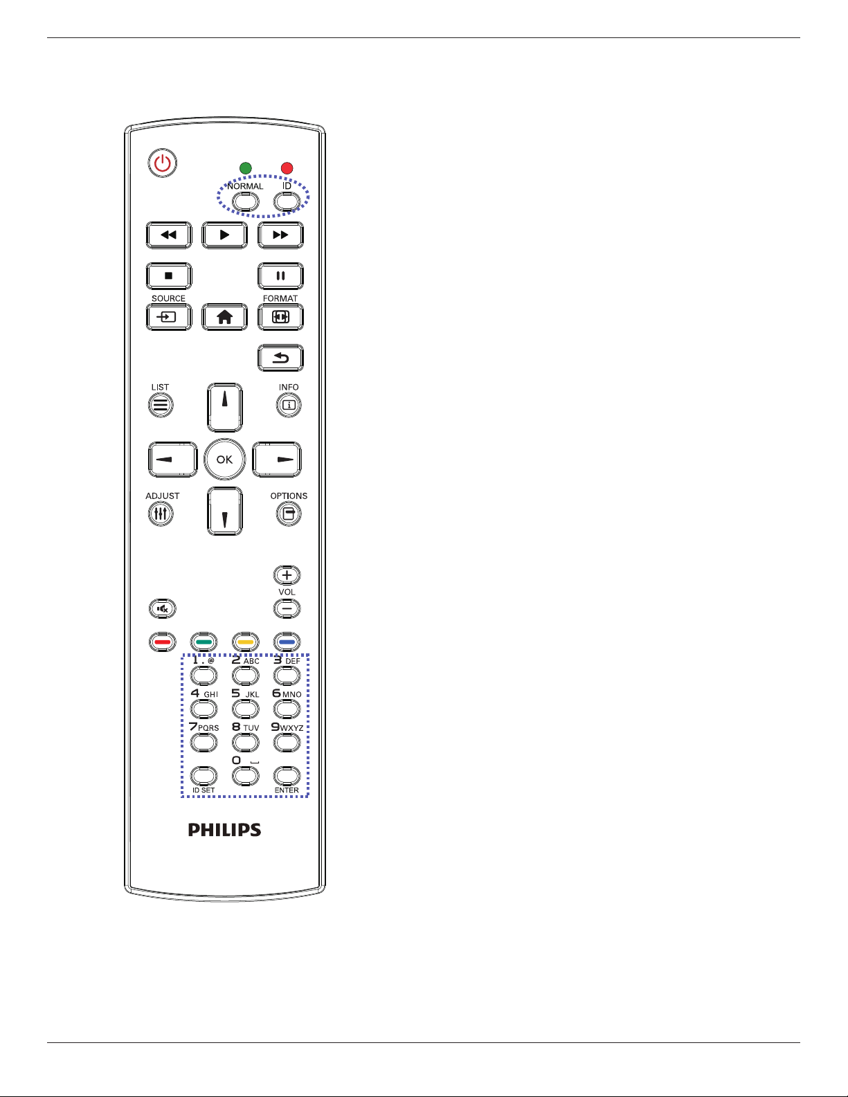
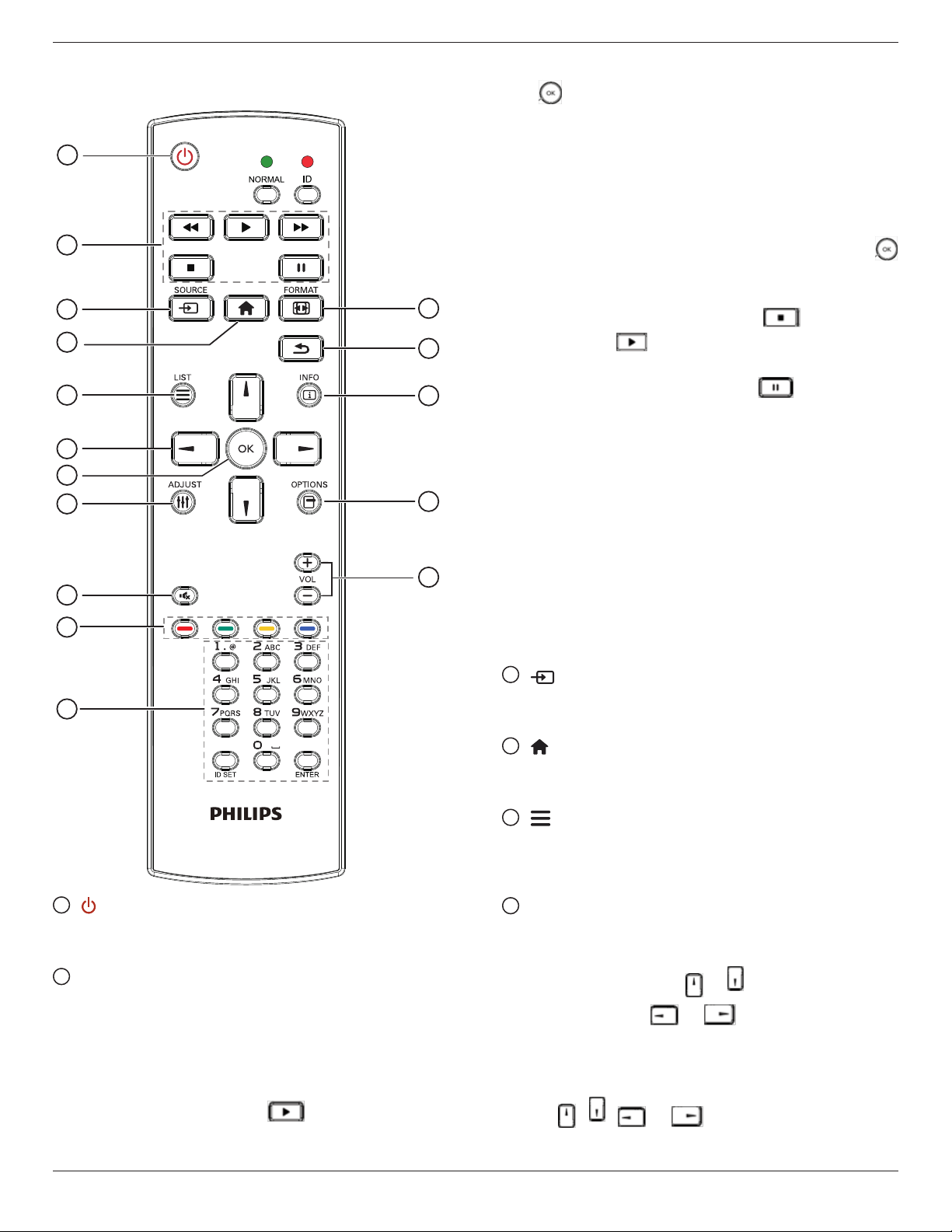
2.3. Remote Control
2.3.1. General functions
1
2
3
4
5
6
7
8
10
9
12
14
15
11
13
16
1
[ ] POWER button
Power ON/OFF.
2
[PLAY] buttons
Control playback of media les.(for Media Input only)
Freezefeature
Pause: Freeze hot key for all inputs content.
Play: Unfreeze hot key for all input content.
3
[ ] SOURCE button
Root Menu: Go to Video source OSD.
4
[ ] HOME button
Root Menu: Go to Main Menu OSD.
Others: Exit OSD.
5
[ ] LIST button
No function.
6
NAVIGATION buttons
[ ]
Root Menu: Go to Smart picture OSD.
Main Menu: Move the highlight bar up to adjust the selected item.
IRDaisyChainMenu: Increase controlled Group ID number.
[ ]
Root Menu: Go to Audio source OSD.
Main Menu: Move the highlight bar down to adjust the selected
item.
IRDaisyChainMenu: Decrease controlled Group ID number.
[ ]
Main Menu: go to previous level menu.
Source Menu: Exit source menu.
VolumeMenu: Decrease Audio Volume.
[ ]
Main Menu: go to next level menu or set selected option.
Source Menu: Go to selected source.
VolumeMenu: Increase Audio Volume.
7
[ ] button
Root Menu: Go to IR daisy chain OSD in Primary/Secondary mode.
Main Menu: Conrm an entry or selection.
8
[ ] ADJUST button
Go to Auto Adjust OSD for VGA only.
9
[ ] MUTE button
Toggle Audio Mute/Unmute.
10
[ ] [ ] [ ] [ ] COLOR buttons
Choose tasks or options.(for Media Input only)
[ ]
Hot key for Window selection function.
11
[Number/ ID SET/ ENTER] button
Enter text for network setting.
Press to set the display ID. Refer to 2.3.2. ID Remote Control
for more detail.
12
[ ] FORMAT button
Change Image Zoom Mode [Full][4:3][Real][21:9][Custom].
13
[ ] BACK button
Return to the previous menu page or exit from the previous
function.
14
[ ] INFO button
Show Information OSD
15
[ ] OPTIONS button
No function.
16
[ ] [ ] VOLUME button
Adjust volume.
65BDL3050Q
7
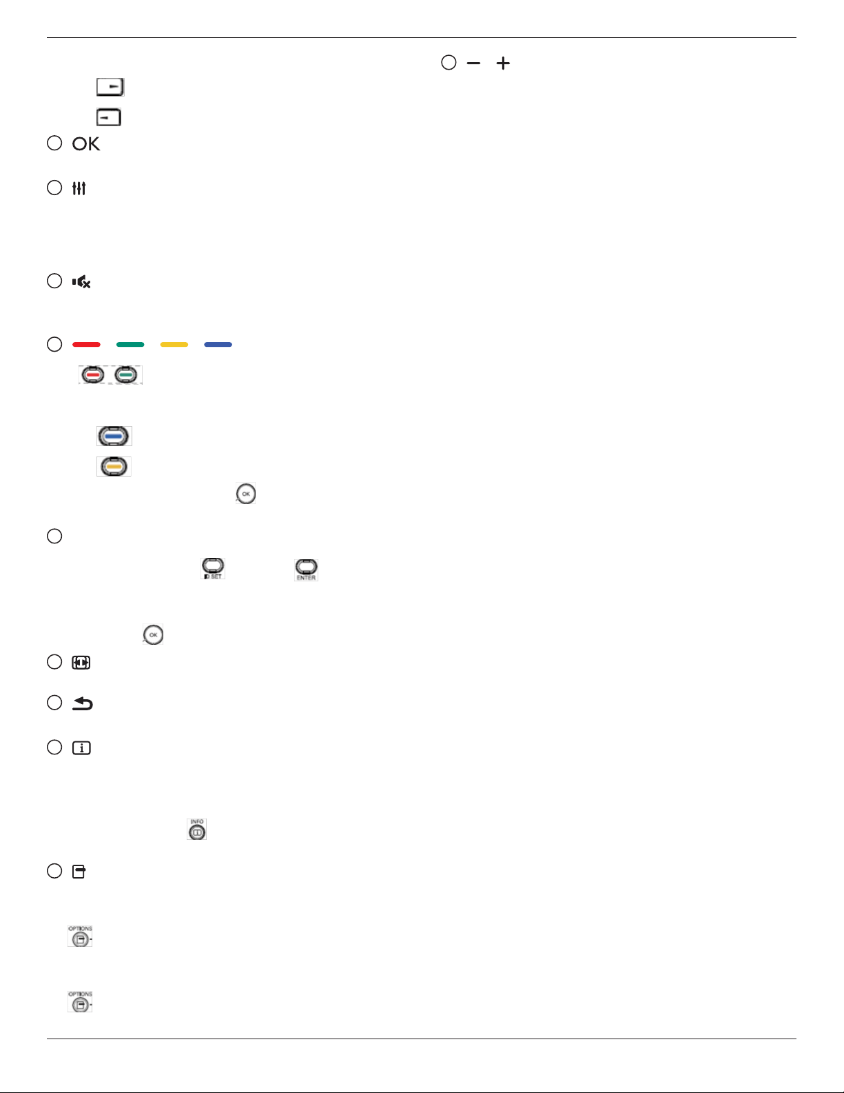
2.3.2. ID Remote Control
You can set the remote control ID when you want to use this remote
control on one of several different displays.
Press [ID] button. The red LED blinks twice.
1. Press [ID SET] button for more than 1 second to enter the ID
Mode. The red LED lights up.
Press the [ID SET] button again will exit the ID Mode. The red LED
lights off.
Press the digit numbers [0] ~ [9] to select the display you want to
control.
For example: press [0] and [1] for display No.1, press [1] and [1] for
display No.11.
The numbers available are from [01] ~ [255].
2. Not pressing any button within 10 seconds will exit the ID Mode.
3. If an error pressing of buttons other than the digits occured, wait
1 second after the red LED lights off and then lights up again, then
press the correct digits again.
4. Press [ENTER] button to conrm. The red LED blinks twice and
then lights off.
NOTE:
• Press [NORMAL] button. The green LED blinks twice, indicating the
display is in normal operation.
• It is necessary to set up the ID number for each display before
selecting its ID number.
65BDL3050Q
8
2.3.3. Remote Control buttons on Android
source
1
2
3
4
5
6
7
8
10
9
12
14
15
11
13
16
1
[ ] POWER button
Turn the display on or put the display to standby.
The button is only controlled by Scalar.
2
[PLAY] buttons
1. Control playback of media(video/audio/picture) les.
There are 4 ways to play media les.
1) File Manager
Find the media le from the File Manager and select it to play.
2) Media Player -> Compose -> edit or new add playlist ->
choose any media les -> press to play the media le
directly.
3)Media Player -> Play -> choose non-empty play list -> press
to play all the media les in the play list.
4) Set media playlist in Boot on Source or Schedule by OSD
menu.
2. Play PDF le
There are 3 ways to play media les.
1) File Manager
Find the pdf le from the File Manager and select it to play.
2) PDF Player -> Play -> choose non-empty play list -> press
to play all the PDF les in the play list.
3) Set pdf playlist in Boot on Source or Schedule by OSD menu.
3. When playing PDF, video or music, press to stop playing.
Then if pressing again, playing will be started from the
beginning of the le.
4. When playing PDF, video or music, press button to pause
playing.
5. All media or pdf les should be put at the folder, which is named
“philips” with sub-folder, under the root directory of the specied
storage (internal/USB/SD Card). All sub-folders (video/photo/music/
pdf) are named by media types and shouldn’t be changed.
videos: {root dir of storage}/philips/video/
photos: {root dir of storage}/philips/photo/
music : {root dir of storage}/philips/music/
pdfs : {root dir of storage}/philips/pdf/
Note that the root directories of three storages are
Internal storage: /sdcard
USB storage: /mnt/usb_storage
SD card : /mnt/external_sd
3
[
] SOURCE button
Choose input source.
The button is only controlled by Scalar.
4
[ ] HOME button
Access OSD menu.
The button is only controlled by Scalar.
5
[ ] LIST button
1. In the content of the web page, move the focus up to the next
clickable items.
2. Move the focus up to the next control or widget such as buttons.
6
NAVIGATION buttons
1. Navigate through menus and choose items.
2. In the content of the web page, these buttons are to control the
scroll bar of the screen. Press or is for moving vertical scroll
bar up or down. Press or is for moving horizontal
scroll bar left or right.
3. For PDF les,
»
when zoom in/out has been performed,
Press , , or to adjust the position of the
screen.
65BDL3050Q
9
»
when zoom in/out has been not performed,
Press to go to the next page.
Press to go to the previous page.
7
[ ] button
Conrm an entry or selection.
8
[ ] ADJUST button
1. In the content of the web page, move the focus down to the next
clickable items.
2. Move the focus down to the next control or widget such as
buttons.
9
[ ] MUTE button
Press to turn the mute function on/off.
The button is only controlled by Scalar.
10
[ ] [ ] [ ] [ ] COLOR buttons
1. : No function on Android source. These two buttons
are only controlled by Scalar.
2. For PDF les,
press button to perform zoom-in;
press button to perform zoom-out.
After zoom-in or zoom-out, press button to revert the pdf le
to the original size.
11
[Number/ ID SET/ ENTER] button
1. No functions for ID SET and ENTER on Android
source. These buttons are only controlled by Scalar.
2. For PDF le, enter the page number by pressing number buttons
and then press button to jump to the specic page.
12
[ ] FORMAT button
Change picture format. The button is only controlled by Scalar.
13
[ ] BACK button
Return to the previous page or exit from the previous function.
14
[ ] INFO button
1. Display information about current input signal. It is shown by
Scalar.
2. Media Player -> Compose -> edit or new add playlist -> choose
any media les -> press to show the information of the
chosen media le.
15
[ ] OPTIONS button
Open toolbox in Media Player or PDF Player.
1. Media Player ->Compose -> Edit or new add playlist -> press
to open toolbox. Toolbox will be slide from the left side of
the screen.
2. PDF Player ->Compose -> Edit or new add playlist -> press
to open toolbox. Toolbox will be slide from the left side of
the screen.
16
[ ] [ ] VOLUME button
Adjust volume. The buttons are only controlled by Scalar.
65BDL3050Q
10
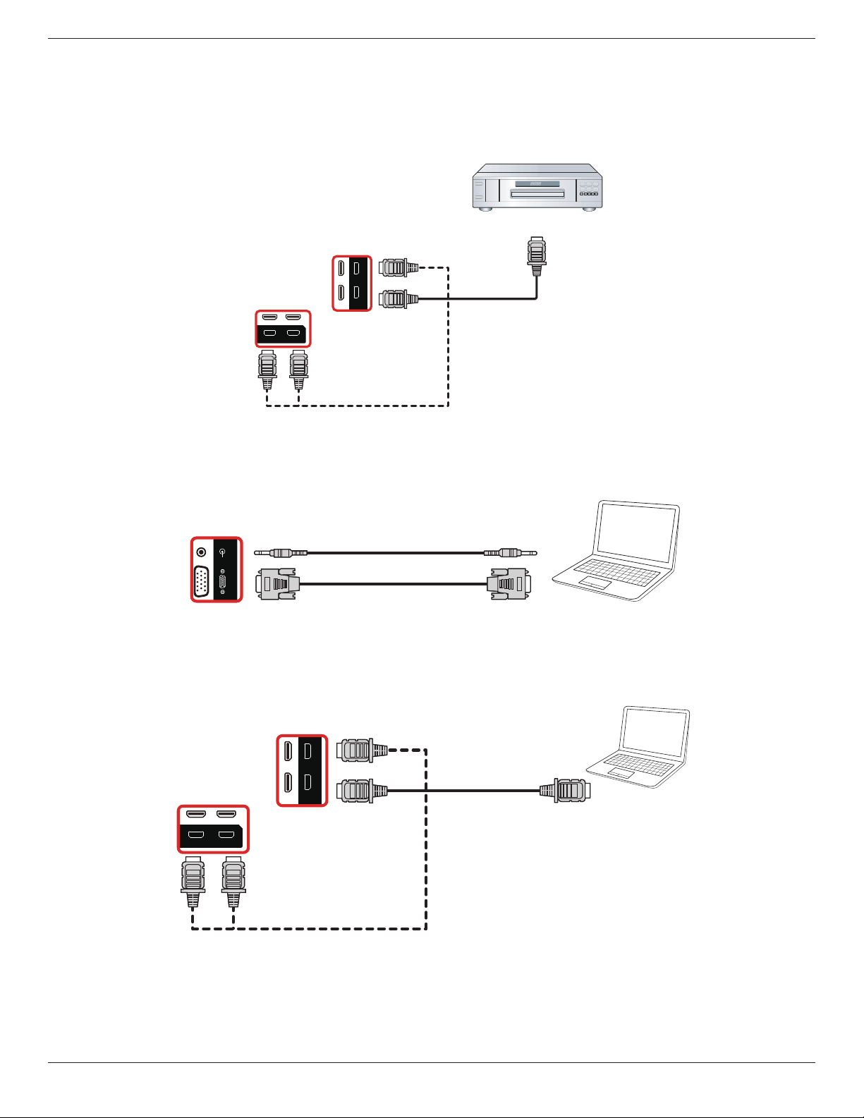
3. Connecting External Equipment
3.1. Connecting External Equipment (DVD/VCR/VCD)
3.1.1. Using HDMI video input
DVD / VCR / VCD
HDMI 3 IN HDMI 4 IN
IR-INIR-OUT
HDMI 1 IN HDMI 2 IN
HDMI Out
[HDMI IN]
3.2. Connecting a PC
3.2.1. Using VGA input
PC
AUDIO IN
IR-INIR-OUT
AUDIO OUT
D-SUB
[VGA IN]
[VGA AUDIO IN]
VGA Out
D-Sub 15 pin
Audio Out
3.2.2. Using HDMI input
PC
HDMI 3 IN HDMI 4 IN
IR-OUT
HDMI 1 IN HDMI 2 IN
HDMI Out
[HDMI IN]
65BDL3050Q
11
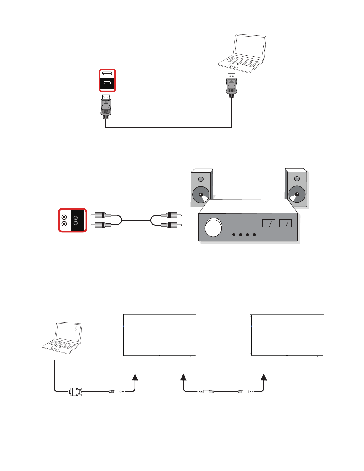
3.2.3. Using DisplayPort input
PC
DisplayPort Out
[DisplayPort IN]
HDMI 1 IN HDMI 2 IN
DP IN
RS232
OUT
3.3. Connecting Audio Equipment
3.3.1. Connecting an external audio device
Stereo Amplifier
[AUDIO OUT] Audio In
AUDIO OUT
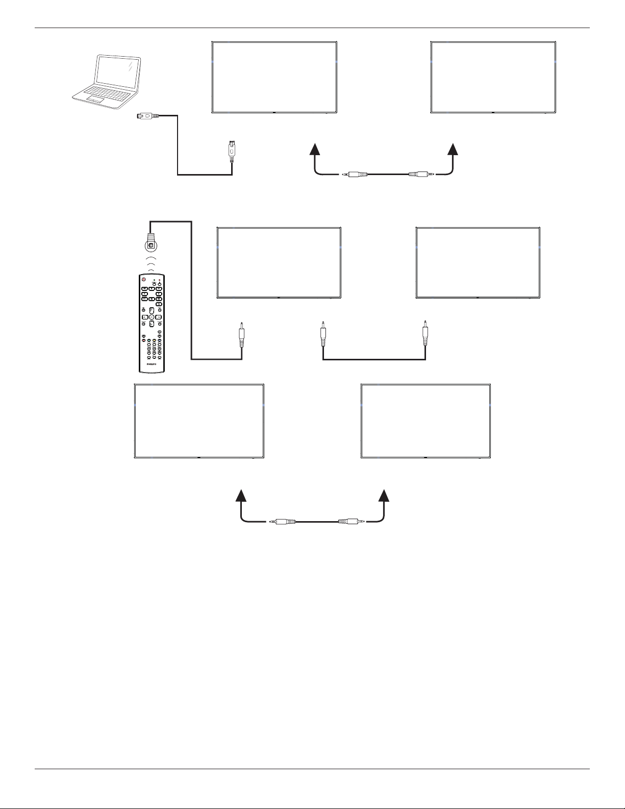
3.4. Connecting Multiple Displays in a Daisy-chain Configuration
You can interconnect multiple displays to create a daisy-chain conguration for applications such as a menu board.
3.4.1. Display control connection
Connect the [RS232 OUT] connector of DISPLAY 1 to the [RS232 IN] connector of DISPLAY 2.
DISPLAY 1
PC
DISPLAY 2
[RS-232C IN]
[RS-232C]
[RS-232C OUT] [RS-232C IN]
65BDL3050Q
12
DISPLAY 1
PC
DISPLAY 2
[RJ-45] [RS-232C OUT] [RS-232C IN]
[RJ-45]
3.5. IR connection
[IR IN]
External
IR Receiver
[IR IN]
[IR OUT]
DISPLAY 1
DISPLAY 2
DISPLAY 1 DISPLAY 2
[RS-232C OUT] [RS-232C IN]
NOTE:
1. This display’s remote control sensor will stop working if the [IR IN] is connected.
2. IR loop through connection can support up to 9 displays.
3. IR in daisy chain via RS232 connection can support up to 9 displays.
65BDL3050Q
13
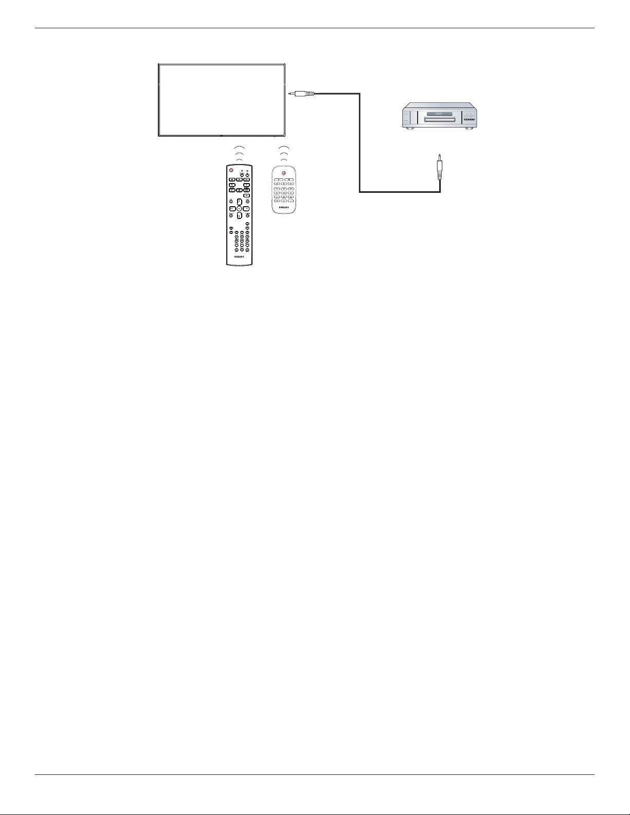
3.6. IR Pass-through Connection
DVD / VCR / VCD
(DVD / VCR / VCD)
Remote Control
[IR OUT]
[IR IN]
65BDL3050Q
14
4. Operation
NOTE: The control button described in this section is mainly on the
remote control unless specied otherwise.
4.1. Watch the Connected Video Source
1. Press
[ ] SOURCE button.
2. Press [ ]
or [ ] button to choose a device, then press [ ]
button.
4.2. Change Picture Format
You can change the picture format to suit the video source. Each video
source has its available picture formats.
The available picture formats depend on the video source:
1. Press [ ] FORMAT button to choose a picture format.
• PC mode: {Full} / {4:3} / {Real} / {21:9}/ {Custom}.
• Video mode: {Full} / {4:3} / {Real} / {21:9}/ {Custom}.
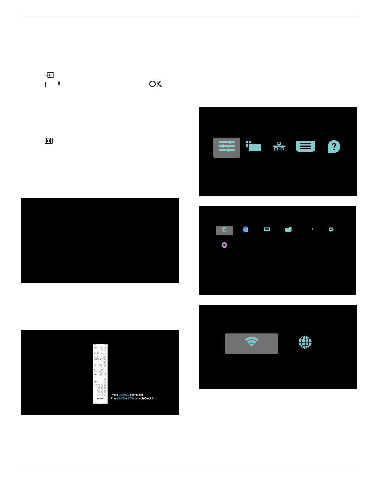
4.3. Overview
1. Android PD launcher:
• Android PD launcher is black page, as below:
• Every apps leave by press back key, the screen will go to android
PD launcher.
• When you return to android PD launcher, the screen will show
hint image, the hint image only show 5 second, as below:
• The hint image will notify you can press source key to change
source.
2. Admin mode:
• You can press “Home + 1888” to enter admin mode. Please
make sure you see the Home OSD menu after “Home” is
pressed, and then press 1888 in sequence. Two continuous
“Home” keys will not be a valid hotkey.
• Admin mode will show ve icons: “Settings”, “Apps”, “Network”
“Storage” and “Help”.
• When you leave admin mode, system will return to last source.
1)Home page of admin mode, this page has ve items: “Settings”,
“Apps”, “Network” “Storage” and “Help”.
Settings : go to settings app.
Applications : show all apps.
Network : set Wi-Fi (optional), Ethernet
Storage : display current PD Android storage information.
Help : display QRcode.
Settings Apps Network Storage Help
2.) Application page:
PDF PlayerMedia PlayerFile ManagerChromium
SmartCMS
Browser Settings
ABC
3
)
Network page
EthernetWi-Fi
65BDL3050Q
15
4
)
Ethernet page
5) Wi-Fi (Optional)
6) Help page:
Display QRcode page.
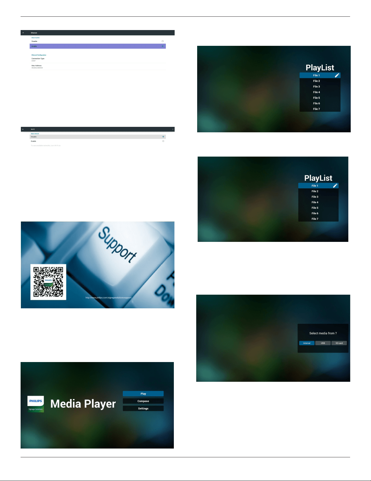
4.4. Media Player introduction:
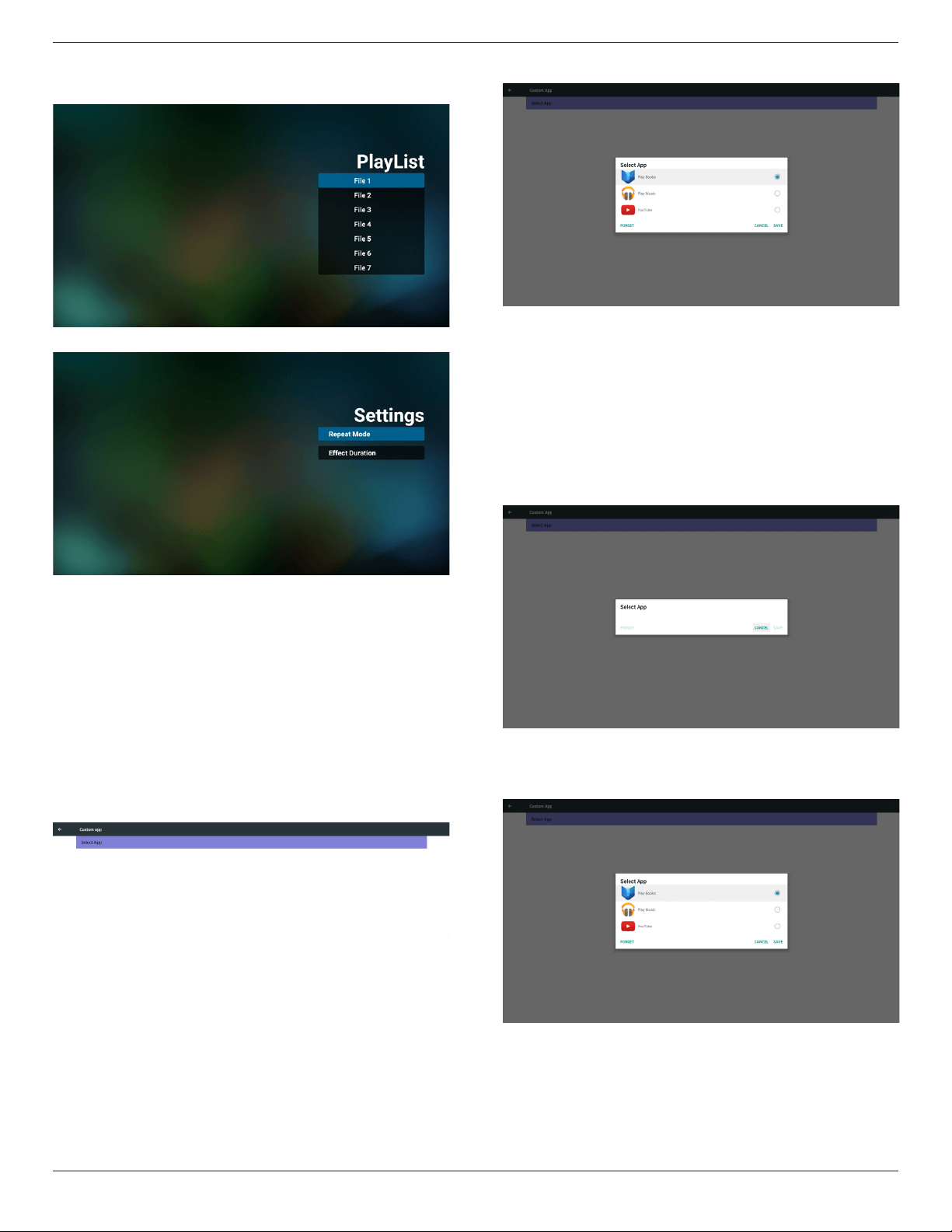
1. Home page of Media Player, this page has three items: “Play”,
“Compose” and “Settings”.
Play : select playlist to play.
Compose: edit playlist.
Settings: setting play properties.
2. Select “Play” on home page, rst you should choose one playlist to
play between FILE 1 and FILE 7.
The pencil icon means the playlist is non-empty.
3. Select “Compose” on home page, rst you should choose one
playlist to edit between FILE 1 and FILE 7.
The pencil icon means the playlist is non-empty.
4. If an empty playlist is chosen, the app will guide you to select the
media source.
All media les should be placed in /philips/ of root directory.
For example,
videos: {root dir of storage}/philips/video/
photos: {root dir of storage}/philips/photo/
music : {root dir of storage}/philips/music/
65BDL3050Q
16
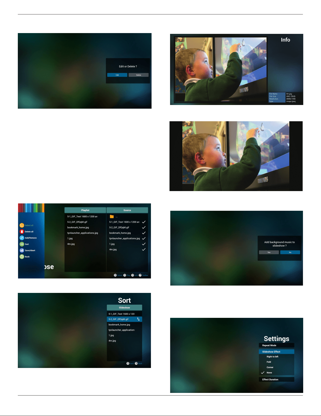
5. You could edit or delete a non-empty playlist, just choose the
desired playlist which is with pencil icon.
6. Once you start to edit a playlist, you will see below screen.
Source - les in storage.
Playlist – les in playlist.
There are 4 icons which map to the keys of remote controller.
Option key – launch slide bar
Play key – play media le.
Info key – show media info.
Ok key – select/unselect le.
6-1 In the slide bar, it helps you to do the following:
- select all : select all storage les.
- delete all : delete all playlist les.
- add/remove : update playlist from source.
- sort : sort playlist.
- save/abort : save or abort playlist.
- back : return.
7. If you choose “Sort” in the slide bar, you can change the order of
les one by one.
8. Press info key after you choose desired le, you will get the detail
information.
9. Press play key after you choose desired le, you will play the media
le directly.
10. If you make a playlist with all images les, before saving, the app
will ask you if you want to have background music while playing
slideshow.
11. Select “Settings” on home page, this page has three parts, “Repeat
Mode”, “Slideshow Effect” and “Effect Duration”.
Repeat Mode : play mode.
Slideshow Effect : photo slideshow effect.
Effect Duration : photo effect duration.
65BDL3050Q
17
12. Media Hotkey
Play : Playback le.
Pause: Pause le.
Fast forward: forward 10 second.
Rewind: back 10 second.
Stop: Stop le and return to start. If the gif le, it like the pause.
13. Media format please refer to SupportedMediaFormats.
14. How to edit playlist via FTP.
Step 1. Create media player text le.
- File name : mpplaylistX.txt, “X” means playlist
number(1,2,3,4,5,6,7).
Ex. mpplaylist1.txt, mpplaylist2.txt
- Content :
Note : if playlist le contains video and music, when the pd plays
music le, the screen will be black.
Step 2. Copy mpplaylistX.txt to “philips” folder of internal storage.
You may use FTP to do this.
- File path : /storage/emulated/legacy/philips
Ex. /storage/emulated/legacy/philips/mpplaylist1.txt
Step 3. Prepare media les to “photo”, “video” and “music” folder
under “philips” folder, internal storage only.
- Ex. /storage/emulated/legacy/philips/photo/xxx.jpg
/storage/emulated/legacy/philips/video/yyy.mp4
/storage/emulated/legacy/philips/photo/zzz.mp3
Step 4. Start media player app, it will auto import media player text
le.
PS. Once the playlist le (text) is imported, if an user change playlist
by remote controller, this change will not be written to playlist text
le.
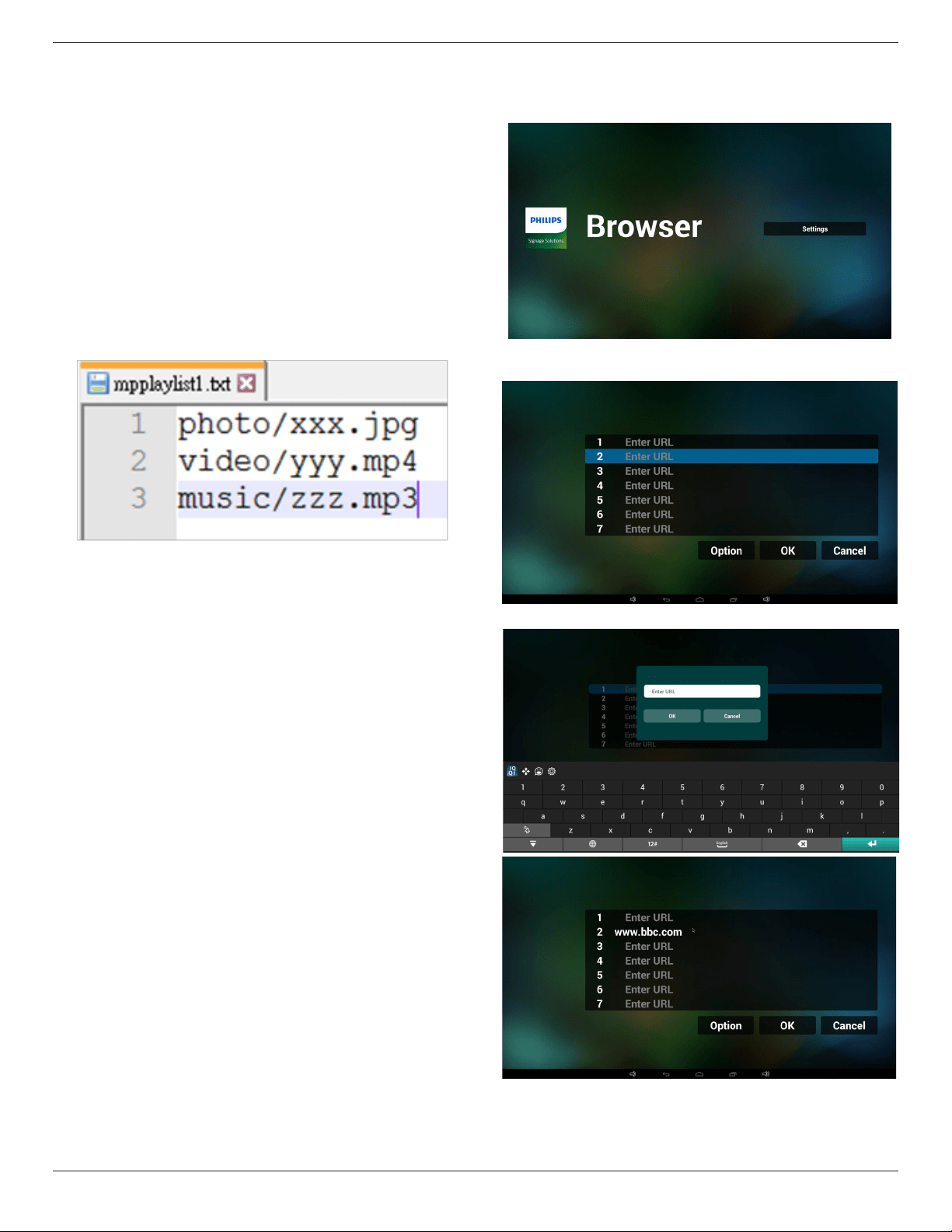
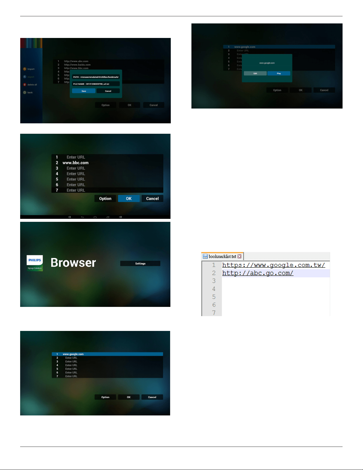
4.5. Browser manual
1. Home page of Browser app, this page has one item: “Settings”.
Press Settings then enter next page.
2. Users can choose 1~7.
Press any one will show a dialog.
3. Enter url and press OK then data will save on List
65BDL3050Q
18
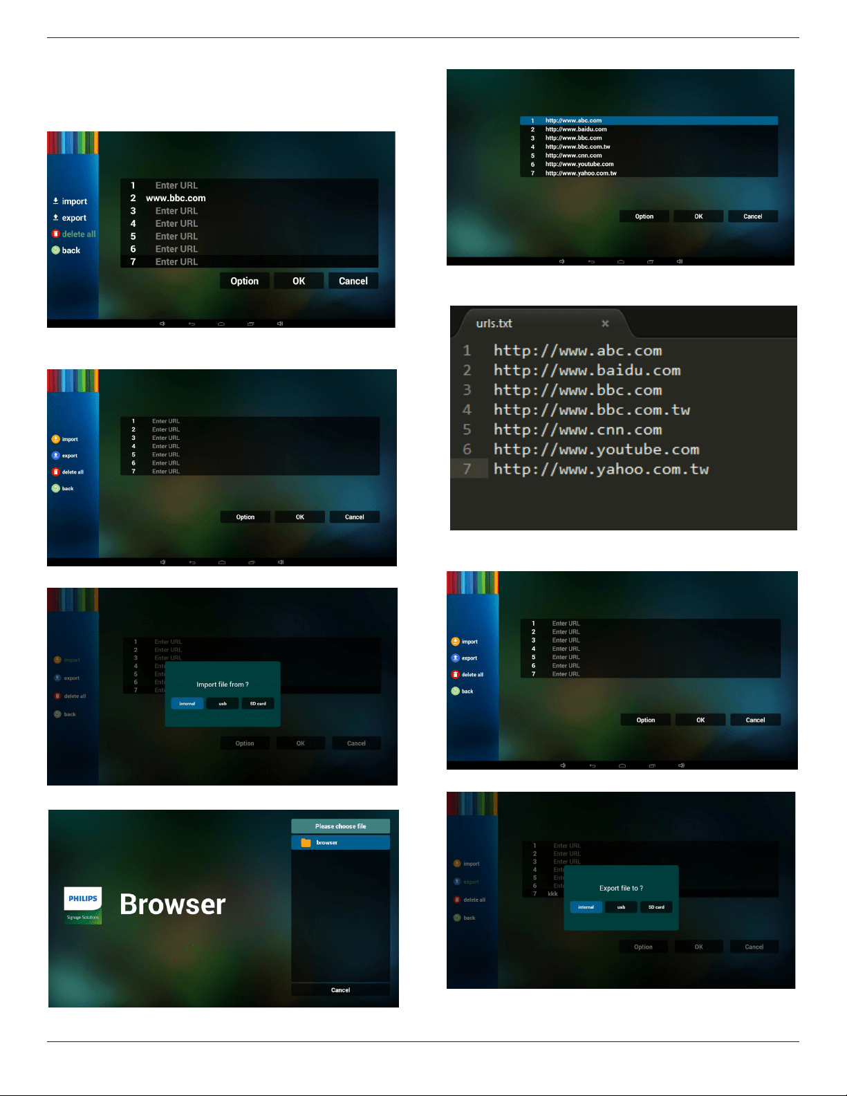
4. Press “Option” then left side will pop up a list
Import : Import url list le
Export : Export url list le
Delete all : Delete all url record on right side
Back : left side list will be closed.
4.1 Import
• Click import
• Choose storage
• Choose le contains urls
• Import le and url will show on list
• File format for import
Format should be like below with le extension “txt”
4.2 Export:
• Click export
• Choose storage
65BDL3050Q
19
• Dialog shows path le will be saved and le’s name.
Press “save” button then urls on list will be saved.
5. Press OK then url records will be saved
.
6. On url list page, if you select non-empty item, it will show a dialog
to ask edit or play url. If press “Edit”, it will show edit url dialog, if
press “Play”, it will show web page of item’s url.
7. OSD menu interaction with Browser
7.1 Boot on source
• Set OSD menu => Conuration1 => Boot on source => Input
be BROWER Play List be 0.
Then PD will show Browser after reboot.
• Set OSD menu => Conuration1 => Boot on source => Input be
BROWER Play List be 1.
Then PD will show web page with 1st Url in Browser app.
7.2 Schedule
Set OSD menu => Advanced option => Schedule =>
On time1, Off time2, Input be BROWSER, any day you want of week,
and Play List.
Finally check the right box.
Then PD will show web page with Url in Browser app at time1 and
nish at time2.
8. How to edit url list via FTP
Step 1. Create media player text le.
- File name : bookmarklist.txt.
- Content :
Step 2. Copy bookmarklist.txt to “philips” folder of internal storage.
You may use FTP to do this.
- File path : /storage/emulated/legacy/philips (for DL, PL)
Ex. /storage/emulated/legacy/philips/bookmarklist.txt
Step 3. Start browser app, it will auto import browser text le.
PS. Once the playlist le (text) is imported, if an user change playlist
by remote controller, this change will not be written to playlist text
le.
65BDL3050Q
20
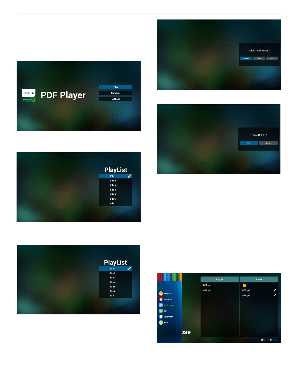
4.6. PDF reader play
1. Home page of PDF Player, this page has three items: “Play”,
“Compose” and “Settings”.
Play : select playlist to play.
Compose: edit playlist.
Settings: setting play properties.
2. Select “Play” on home page, rst you should choose one playlist to
play between FILE 1 and FILE 7.
The pencil icon means the playlist is non-empty.
3. Select “Compose” on home page, rst you should choose one
playlist to edit between FILE 1 and FILE 7.
The pencil icon means the playlist is non-empty.
4. If an empty playlist is chosen, the app will guide you to select the
media source.
All media les should be placed in /philips/ of root directory. For
example,
pdfs : {root dir of storage}/philips/pdf/
5. You could edit or delete a non-empty playlist, just choose the
desired playlist which is with pencil icon.
6. Once you start to edit a playlist, you will see below screen.
Source - les in storage.
Playlist – les in playlist.
There are 4 icons which map to the keys of remote controller.
Option key – launch slide bar
Play key – play media le.
Info key – show media info.
Ok key – select/unselect le.
6-1. In the slide bar, it helps you to do the following:
- select all : select all storage les.
- delete all : delete all playlist les.
- add/remove : update playlist from source.
- sort : sort playlist.
- save/abort : save or abort playlist.
- back : return.
65BDL3050Q
21
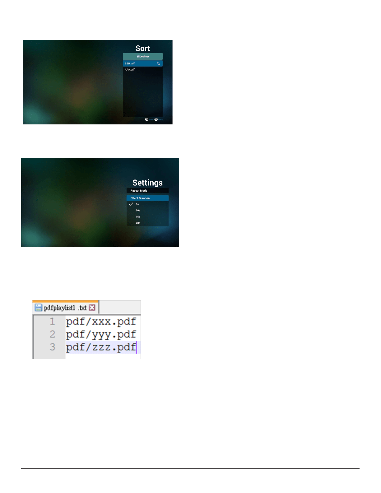
7. If you choose “Sort” in the slide bar, you can change the order of
les one by one.
8. Select “Settings” on home page, this page has two parts, “Repeat
Mode” and “Effect Duration”.
Repeat Mode : play mode.
Effect Duration : photo effect duration.
9. How to edit pdf list via FTP.
Step 1. Create pdf player text le.
- File name : pdfplaylistX.txt, “X” means playlist
number(1,2,3,4,5,6,7).
Ex. pdfplaylist1.txt, pdfplaylist2.txt
- Content :
Step 2. Copy pdfplaylistX.txt to “philips” folder of internal storage.
You may use FTP to do this.
- File path : /storage/emulated/legacy/philips (for DL, PL)
Ex. /storage/emulated/legacy/philips/pdfplaylist1.txt
Step 3. Prepare pdf les to “pdf ” folder under “philips” folder,
internal storage only.
- Ex. /storage/emulated/legacy/philips/pdf/xxx.pdf
/storage/emulated/legacy/philips/pdf/yyy.pdf
/storage/emulated/legacy/philips/pdf/zzz.pdf
Step 4. Start pdf player app, it will auto import pdf player text le.
PS. Once the playlist le (text) is imported, if an user change playlist
by remote controller, this change will not be written to playlist text
le.
Media Hotkey:
Play : Playback le.
Pause: Pause page.
Fast forward: go to next page, if the page is end of the le, it will go
to next le.
Rewind: back to last page, if the page is rst of the le, it will back to
last le.
Stop: return to rst page of le
Color Hotkey:
Blue : Zoom in.(+10%)
Yellow : Zoom out.(-10%)
OK : Restore zoom
Arrow keys:
Up/Down/Left/Right : Adjust page. (When the page has zoomed in/
out)
Left : Previous Page. (When the page has not zoomed in/out)
Right : Next Page. (When the page has not zoomed in/out)
Combination key:
Number key + OK key : select specic page, and press ok key to
change page.
- Press number key.
- Press OK key, the bottom of the page will show the page number,
if page number over total page number, it will not change page and
show current page number at the bottom of the page.
65BDL3050Q
22
4.7. CMND & Play
1) Server
Setup CMND & Play server address
2) Account
Setup CMND & Play account
3) PIN Code
Setup CMND & Play PIN code
(4) Version
There are two options, Ver.2 and Ver.3
Ver. 2
use 2.0/2.2 agreement
Ver. 3
use 3.0/3.1 agreement
(5) Content
There are internal storage/SD card/USB storage 3 options for
selecting.
When Ver.2, Server/Account/PIN code will be gray and unavailable.
Internal storage
SD card
USB storage
CONTENT
Settings
Server
Account
PIN Code
Version
Ver.2
CMND & Play
When Ver.3, Server/Account/PIN code is available.
Internal storage
SD card
USB storage
CONTENT
Settings
Server
Account
PIN Code
Version
Ver.3
CMND & Play
4.8. Custom App
User can set up the application for Customer Source
Note:
(1) Only display User Installed app.
(2) Will not show up system pre-install app.
4.8.1. OSD Menu operation:
RCU: Source -> Custom
If set up customer APK, PD will open customer app when switch source
to Customer mode.
If no set up customer APK, PD will show Black screen when switch
source to Customer mode.
Select App
Custom App
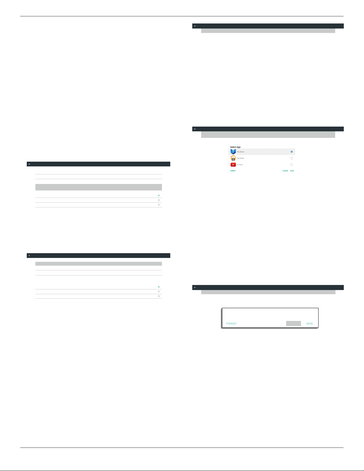
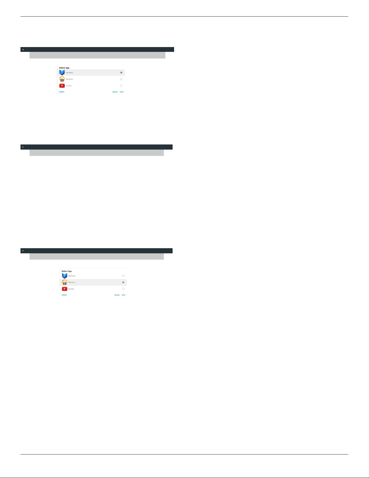
4.8.2. Function Introduction
Custom App
Select App
Play Books
Save
Select the App, click the Save will perform the function of storage.
Forget
After press the Forget, can remove previously stored information.
Cancel
Don’t do any change, directly closed Windows.
If no customer installed apk, the list will be blank.
The list will be blank and “Save””Forget” will be gray and useless.
Select App
Select App
FORGET
CANCEL
SAVE
Custom App
65BDL3050Q
23
If customer installed apk,user can select customer installed apk in list
• Case 1: Not set up Custom App case.
Customer app will show up and focus on rst item automatically.
Custom App
Select App
Play Books
After set up, the setting screen display the app name.
Select App
Play Books
Custom App
• Case 2: Set up Custom App case(there is entity circle to the right of
icon)
Custom App
Select App
Play Music
65BDL3050Q
24
5. Signage display
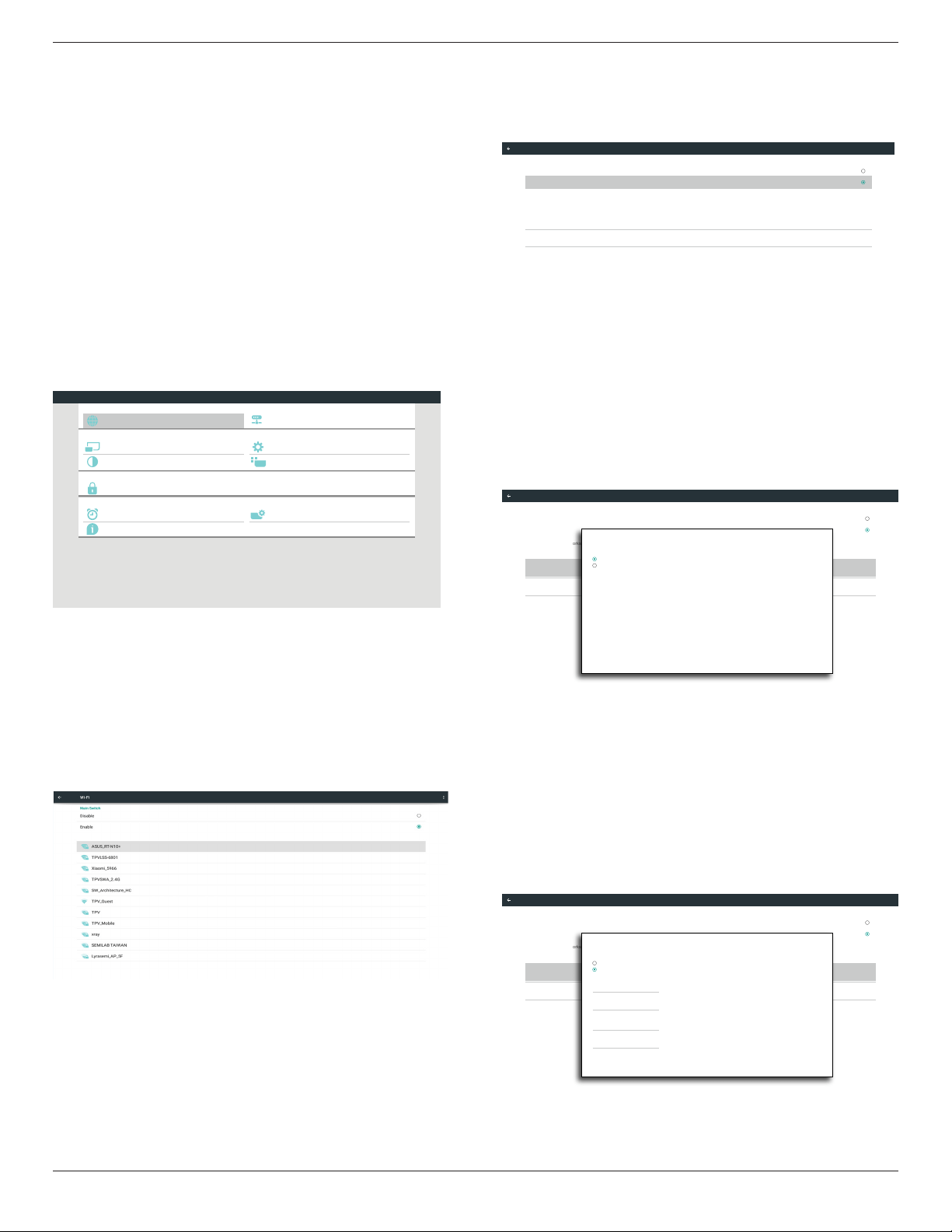
5.1. Setting
Main items:
(1) Wi-Fi (Show up when plug in Wi-Fi dongle)
(2) Ethernet
(3) Proxy
(4) Signage Display
(5) System Tools
(6) Display
(7) Apps
(8) Security
(9) Date & time
(10) Developer options
(11) About
Developer options
System Tools
Proxy
Signage Display
Ethernet
Display
Apps
Security
Date & time
About
System
Personal
Device
Network
Settings
5.2. Wi-Fi
Via Enable/Disable to control Wi-Fi On/OFF. After Enable, the screen
will list all available Wi-Fi AP.
Note :
1. Ethernet will be disable automatically if Wi-Fi turn on and connect
to network.
2. A particular model of Wi-Fi module is required. Please consult the
dealer or service technician for help.
5.3. Ethernet
Enable/Disable to turn on/off Ethernet
After enable Ethernet, the settings will show:
(1) Connection Type (Available connection type: DHCP/Static IP)
A. DHCP
B. Static IP
C. IP Address
D. Netmask
E. DNS Address
F. Gateway
(2) Mac Address
Connection Type
Static IP
Mac Address
00:24:67:21:57:ea
Ethernet Configuration
Main Switch
Disable
Enable
To see available networks, turn Ethernet on.
Ethernet
5.3.1. DHCP
DHCP mode:
(1) Cannot modify IP Address, Netmask, DNS Address and Gateway.
(2) If connect successfully, it will display current network
conguration.
Connection Type
DHCP
Mac Address
00:24:67:21:57:ea
Ethernet Configuration
Main Switch
Disable
Enable
To see available networks, turn Ethernet on.
Ethernet
Ethernet Configuration
DISCARD SAVE
Connection Type
DHCP
Static IP
IP Address
172.17.2.12
Netmask
255.255.255.0
DNS Address
172.16.0.178
Gateway
172.17.2.254
5.3.2. Static IP
In Static IP mode, user can input IP Address, Netmask, DNS address and
Gateway
Note:
IP address, netmask, DNS address and gateway address input limitation
(1)Format:
I. number 0-9
II. decimal point “.”
Connection Type
Static IP
Mac Address
00:24:67:21:57:ea
Ethernet Configuration
Main Switch
Disable
Enable
To see available networks, turn Ethernet on.
Ethernet
Ethernet Configuration
DISCARD SAVE
Connection Type
DHCP
Static IP
IP Address
Netmask
DNS Address
Gateway
65BDL3050Q
25
5.4. Proxy
Browser connect to Proxy server and ask Proxy server to connect
some website on Internet.
Enable/Disable to turn on/off Proxy server.
• Click “Enable” to switch proxy function “ON”
• Input the “Proxy hostname”. (Proxy server IP address)
• Input the “Proxy port”. (Proxy server port number)
• Select an “Type”. (Proxy server type.)
• Done.
- If the proxy server is need an authentication to connect, please
“check on” the Authentication and input Username & Password.
- If the proxy server is not need an authentication to connect.
Proxy hostname
Proxy port
Type
HTTP
Proxy settings
Authentication
Username
Password
Authentication
Main Switch
Disable
Enable
Proxy
Note:
• Proxy type in HTTP, HTTPS, SOCKS4, SOCKS5 are support.
• Only support the connection through the proxy server with
TCP port 80 & 443 & 5228.
• Proxy server with authentication on Windows Sever Series is
not support.
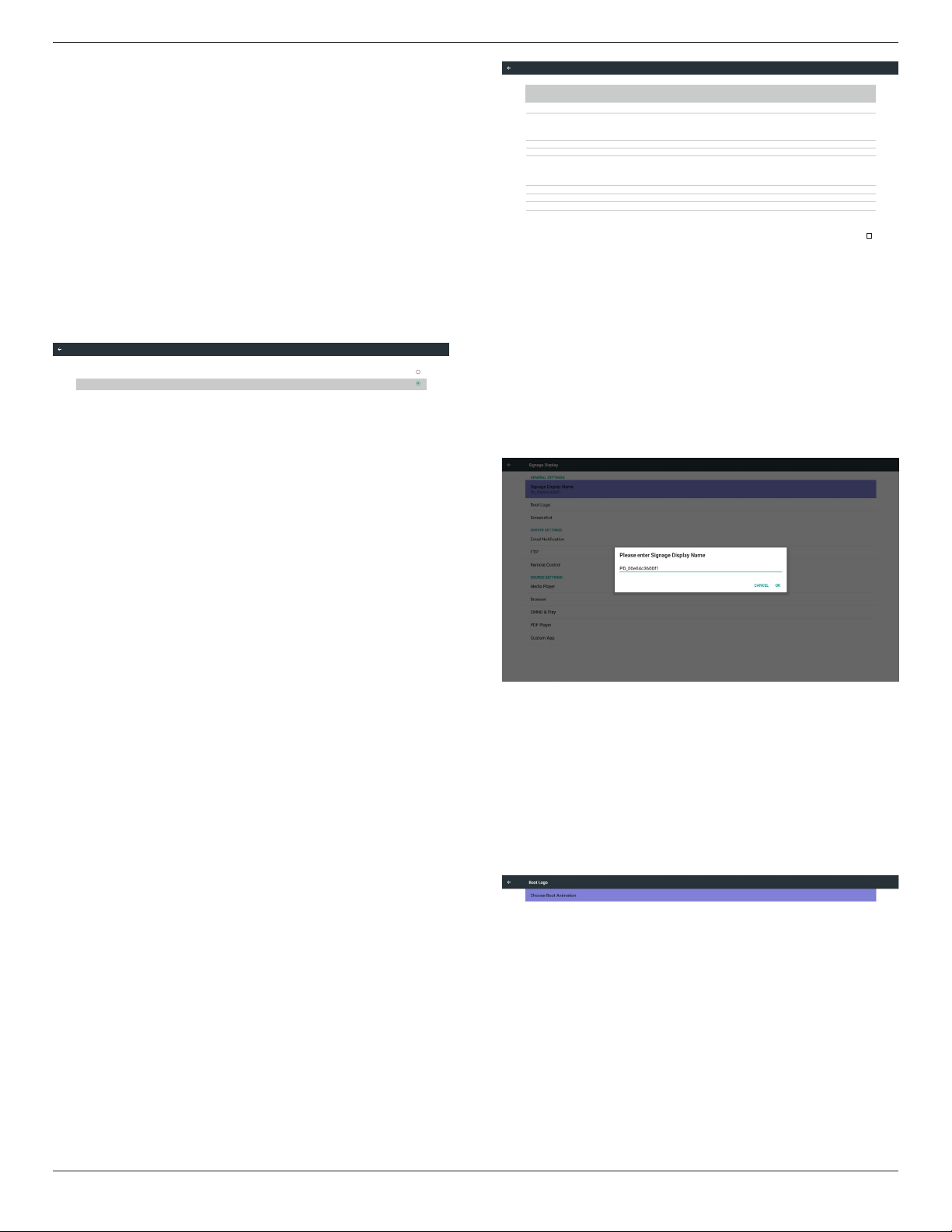
5.5. Signage Display
Divide into 4 groups: General Settings / Server Settings / Source Settings
/ Security
(1) General Settings
A. Signage Display Name
B. Boot Logo
C. Screenshot
(2) Server Settings
A. Email Notication
B. FTP
C. Remote Control
D. SICP Network Port
(3) Source Settings
A. Media Player
B. Browser
C. CMND & Play
D. PDF Player
E. Custom app
(4) Security
A. External Storage
(5) Other
A. TeamViewer Support
B. Platform Web API
Email Notification
FTP
Remote Control
SCIP Network Port
Server settings
Media Player
Browser
CMND & Play
PDF Player
Custom App
Source settings
General settings
Signage Display Name
PD_0024672157ea
Security
External Storage
SD card/USB External Storage Unlock
Boot Logo
Screenshot
Signage Display
5.5.1. General Settings
1. Signage Display Name
Set up PD name “PD_” + Ethernet Mac Address.
Note:
Input limitation:
(1) length: Max 36 characters
(2) format: no limit
2. Boot Logo
1) Scalar OSD menu to control Android boot logo enable/disable
Scalar OSD menu operation
RCU: Home -> Conguration2 -> Logo -> On/Off/User
In user mode, user can choose their own boot logo animation le.
Note:
(1) Boot animation le name: bootanimation.zip
(2) Will pop-up a window for user to select USB and SD card. No
priority issue.
65BDL3050Q
26
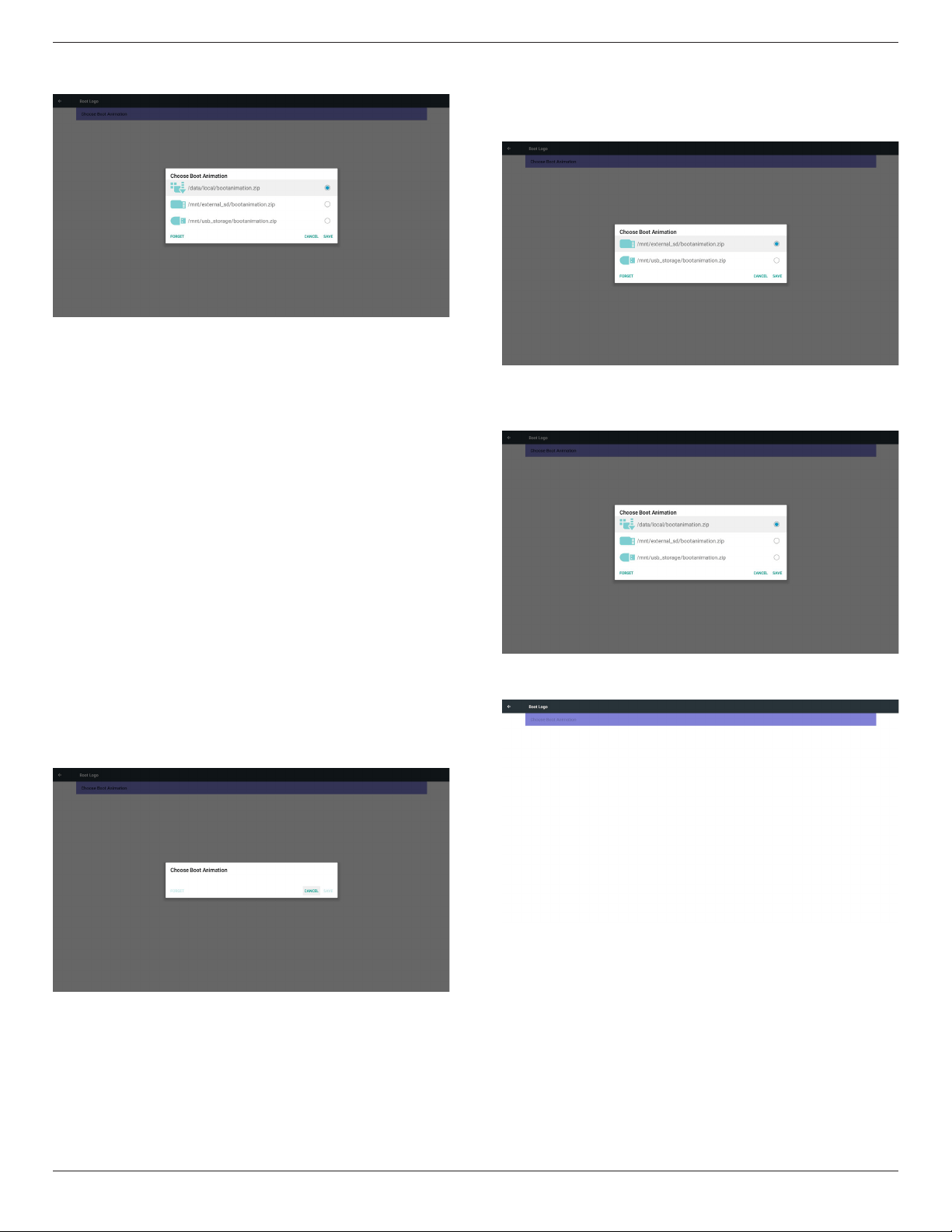
2) When boot logo selected, PD will check if there is bootanimation.
zip under USB and SD card.
Function introduction:
a. Option description
/data/local
Use customized boot animation le which is copied from SD card or
USB
/mnt/external_sd
Use boot animations le under SD card
/mnt/usb_storage
Use boot animations le under USB
b. Save
Press save key to save SD card or USB bootanimation.zip to /data/
local and set it as boot logo.
c. Forget
Press Forget key to delete /data/local bootanimation.zip and not
show boot logo.
d. Cancel
Close dialogue w/o changes.
Scenario introduction:
Case 1
The user don’t settle customized boot logo. PD does not nd any
bootanimation.zip le under SD and USB. The list will be blank. Save
and Forget button will be gray and useless.
Case 2
The users do not settle customized boot logo. PD nd
bootanimation.zip le under SD and USB. The screen will show
bootanimation.zip and select the rst le automatically.
Case 3
The user settle customized boot logo, the screen will show /data/
local/bootanimation.zip.
3) If OSD menu Logo item is On or Off, the users cannot choose
boot animation in Android settings.
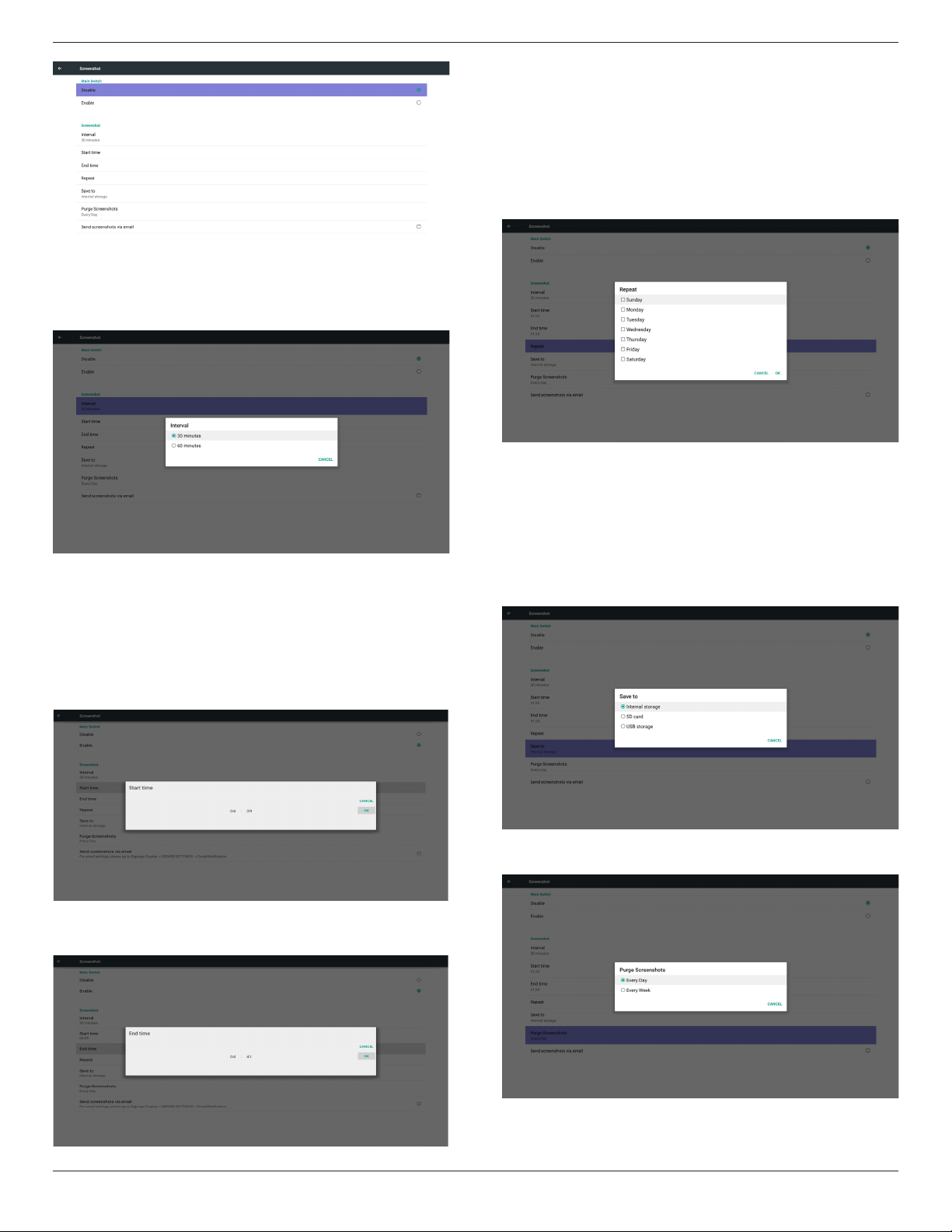
3. Screenshot
Via Enable/Disable to control screenshot On/Off.
After Enable, user can set screenshot timeslot and save path.
Note:
Time slot of deletion and screenshot:
(1) Will delete picture at initial time 0 sec.
(2) Will screeshot at rst 40 sec.
(3) Media player, Browser, CMND & play, PDF reader, Custom source
are supported.
(4) Screenshot will not include video container
65BDL3050Q
27
1) Interval
Set up interval timeframe. 30 mins or 60 mins.
2) Start Time
Set up screenshot start time.
Note:
(1) If no start time, the screen will show current time automatically
(2) Just press Back key to exit dialog for Set up
(3) Start time cannot be newer than End time. It will show Error
toast.
3) End Time
Set up screenshot End time
Note:
(1) If no End time, the screen will show current time automatically
(2) Start time cannot be newer than End time. It will show error
toast.
4)Repeat
Set screenshot repeat cycle. User can choose screenshot time frame.
(Multiple selection)
5)Save to
Set up screenshot save path. Internal storage, SD card or USB
storage.)
Note:
picture storage path
(1) In root of internal storage/usb storage/sd card, PD will create
folder automatically.
(2) The picture will save to philips/Screenshot/.
6) Purge Screenshots
Set up purge timeframe. One day or One week.
65BDL3050Q
28
(7) Send screenshots via email
After check this item, it will send screenshot to email of administrator
Please refer to Email notication
Note:
Please conrm Email setting is done.
5.5.2. Server Settings
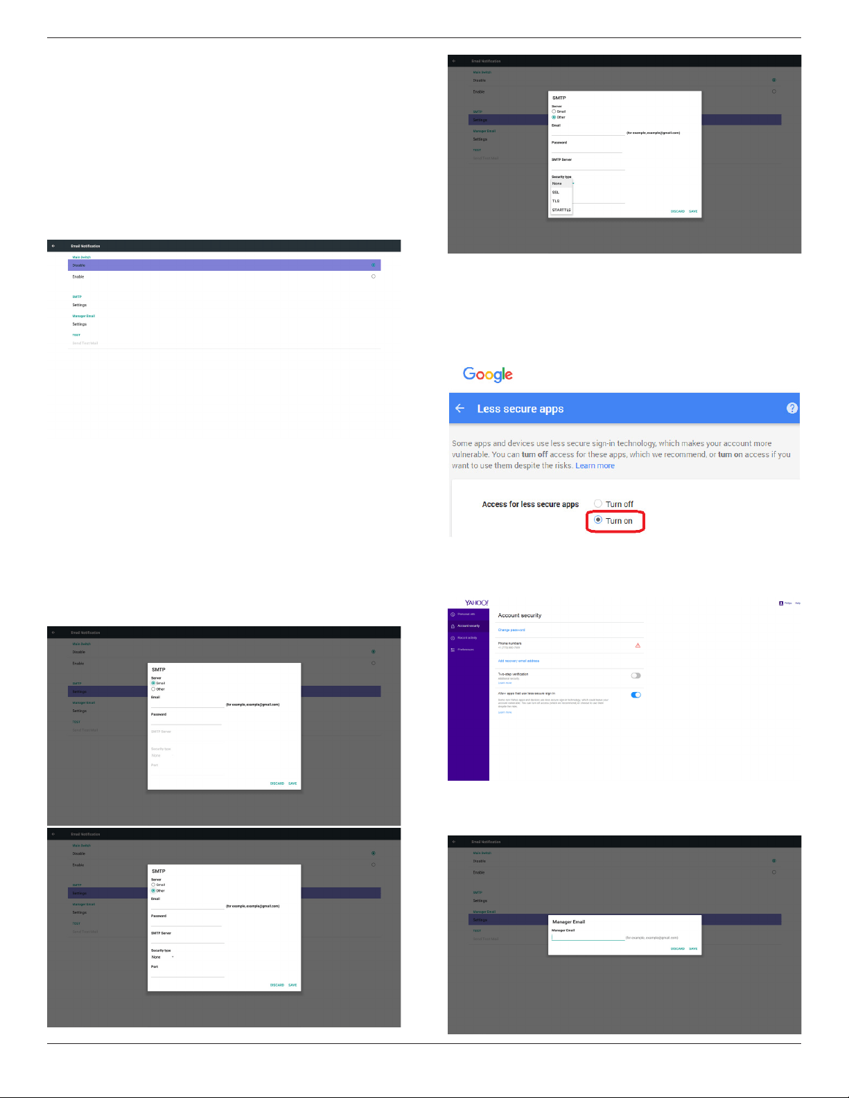
1. Email Notication
Via Enable/Disable to control Email On/Off)
After Enable, user can set up Email notication conguration.
1) SMTP
Set SMTP conguration)
User can set Gmail account or other mail account.
User can select other mail account and set up SMTP server, Security
type and port item
Note
Password input limitation
(1) Length: 6-20 characters
(2) Format: no limit
(3) unavailable port: 5000
Gmail safety setting
If Gmail is not working when the settings are completed, please test
the Gmail account via a PC and the below link
https://www.google.com/settings/security/lesssecureapps
And conrm on “Access for less secure apps”the“Turn on” item is
selected.
Yahoo Email Security Setting
If Yahoo Email is not working when setting complete, please conrm
“Allow apps that use less secure sign in” item is enabled.
2)Manager Email
Email
Set up Receiver mail account
65BDL3050Q
29
3)Test
Send Test Mail
To test Gmail account receive/send function.
Note
(1) When Email is Disable, “Send Test Mail Button” button will gray
out
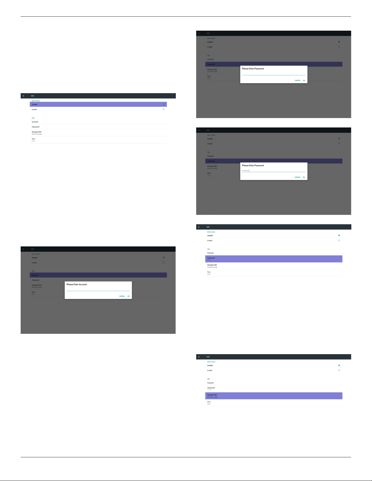
2. FTP
Via Enable/Disable to control FTP On/Off. After set up, PD can share
FTP les.
1) Account
Set up FTP account
Note:
Input limitation
(1) Length: 4-20 characters
(2) Format:
I. English a-z and A-Z
II. Number 0-9
2) Password
Set up FTP password.
Note:
Input limitation
(1) Length: 6-20 characters
(2) Format:
I. English a-z and A-Z
II. Number 0-9
FTP password display
(1) Will show “*” symbol to instead password if set up password via
remote control.
(2) After set up, the password text will show as “*” symbol.
Before password input:
After password input:
Set up completed screen:
3)Storage Path
Show default path: Internal storage
Note:
Can only display Internal storage, cannot be modied.(Only show
path)
65BDL3050Q
30
4) Will show Server is unbinded if Remote control server feedback
unbinded status.
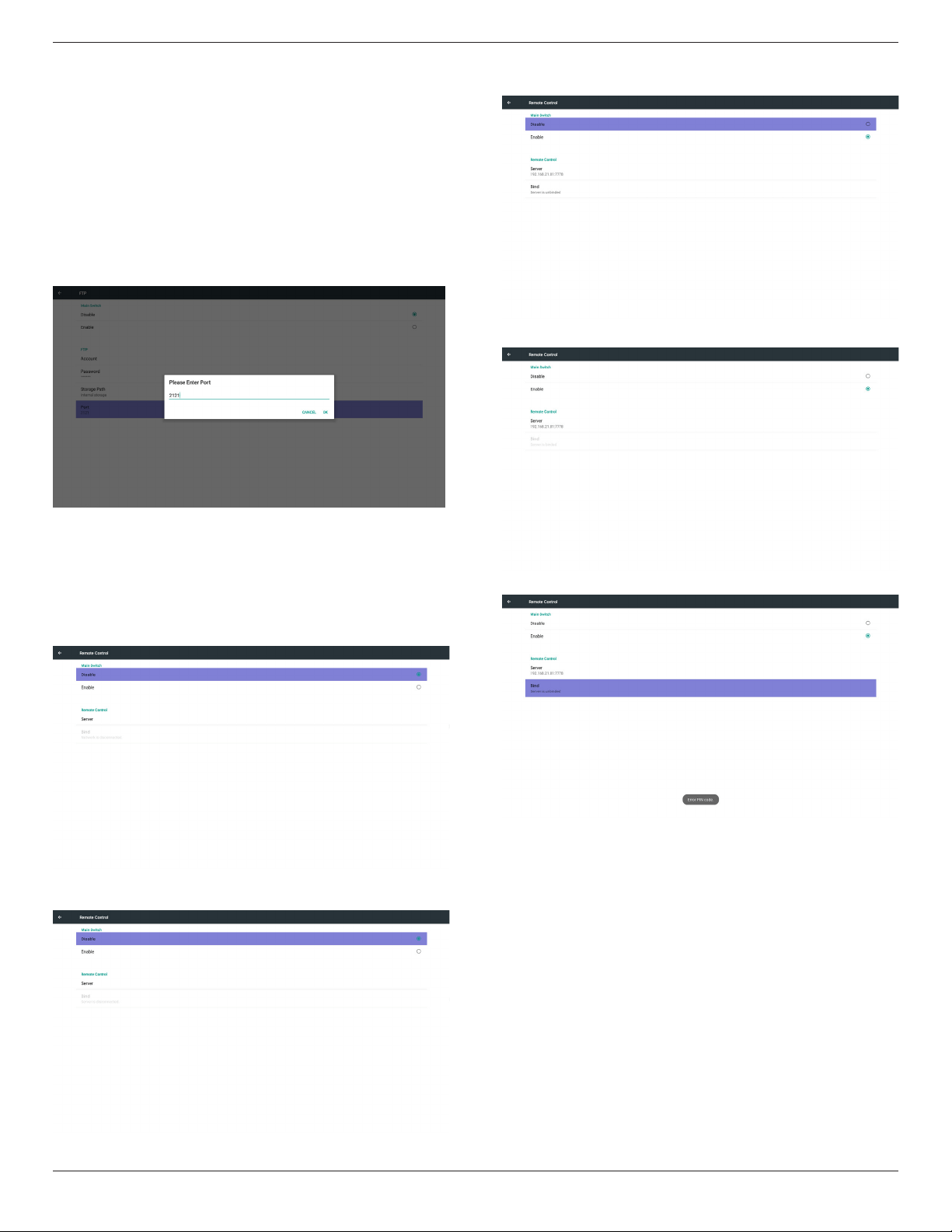
5) Port
Set up FTP port number. Default: 2121
Note:
Input limitation
(1) Length: Max 5 characters
(2) Range: 1024 ~ 65535
(3) Format: Number 0-9
(4) Unavailable port: 5000
(5) The port number must more than 1024
3. Remote Control
Via Enable/Disable to Control Remote Control On/Off
User can input Server address. If server does not registered, it will ask
user for PIN code.
Bind status:
(1) Will show network is disconnected if not yet connects to
network.
(2) Will show Server is disconnected if network connected but
remote control server disconnected.
(3) Will show Server is unbinded if Remote control server feedback
unbinded status.
(4) Will show Server is binded if Sever binded successfully.
(5)Will show Error PIN code if input incorrect PIN code.
4. SICP Network Port
Change SICP Network Port.
Note:
1. Range: 1025-65535
2. unavailable port: 8000 / 9988 / 15220 / 28123 / 28124

65BDL3050Q
31
5.5.3. Source Settings
1. Media Player
Can Edit Media Player play list and effect settings.
(1) Open Media Player Player List edit page.
(2) Open Media Player slideshow effect edit page.
2. Browser
Can edit Bookmark conguration.
Open Browser setting page.
3. CMND & Play
1) Server
Setup CMND & Play server address
2) Account
Setup CMND & Play account
3) PIN Code
Setup CMND & Play PIN code
(4) Version
There are two options, Ver.2 and Ver.3
Ver. 2
use 2.0/2.2 agreement
Ver. 3
use 3.0/3.1 agreement
(5) Content
There are internal storage/SD card/USB storage 3 options for
selecting.
When Ver.2, Server/Account/PIN code will be gray and unavailable
.
When Ver.3, Server/Account/PIN code is available.
65BDL3050Q
32
4. PDF Player
(1) Open PDF Player Player List edit page.
(2) Open PDF Player effect edit page.
5. Custom App
User can set up the application for Customer Source.
Note
(1) Only display User Installed app.
(2) Will not show up system pre-install app.
Scalar OSD menu operation
RCU: Source -> Custom
If set up customer APK, PD will open customer app when switch source
to Customer mode.
If no set up customer APK, PD will show Black screen when switch
source to Customer mode.
Function introduction
(1) Save
Select App and press Save key to save it.
(2) Forget
Press Forget key to clean previous stored data
(3) Cancel
No change, close window directly
If no customer installed apk, the list will be blank.
No option for choose. Save and Forget key will be gray and
unavailable.
User can select customer installed apk in list
No setup Custom App
Screen will show available apps and focus on rst app item automatically.
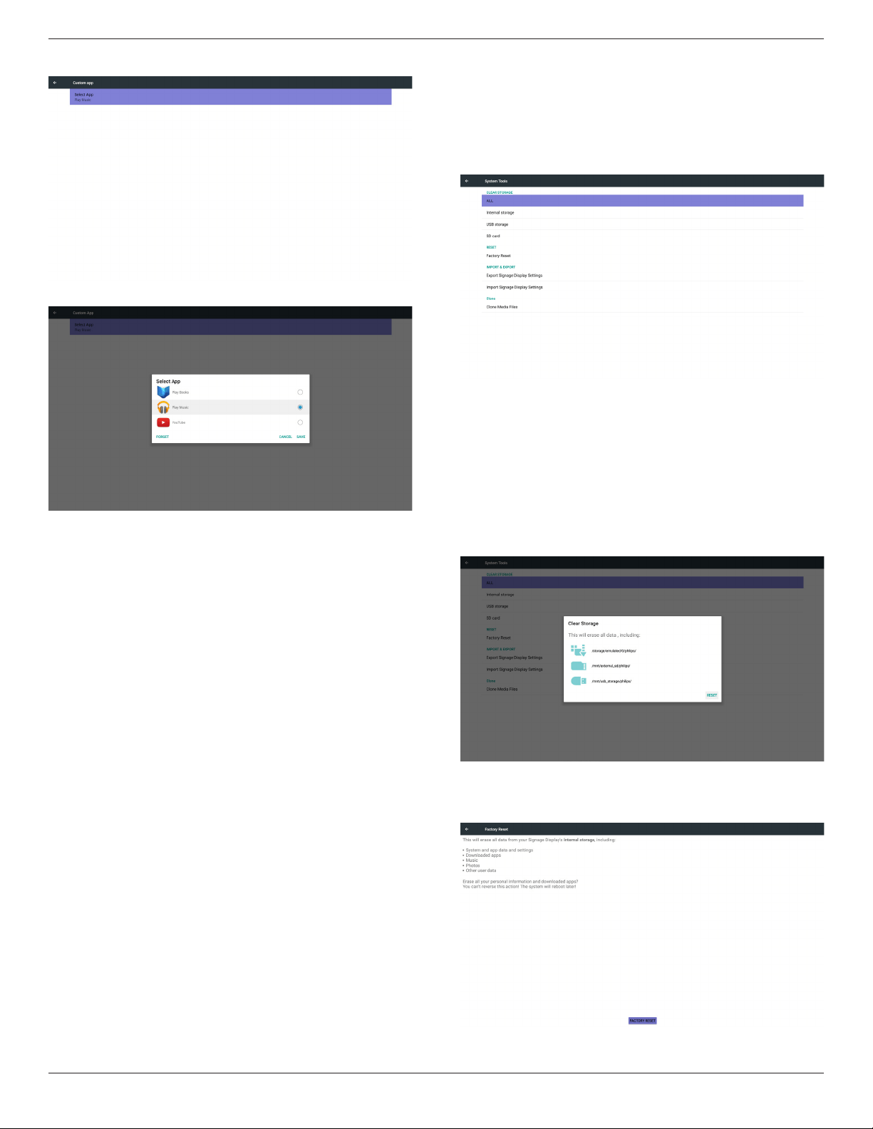
65BDL3050Q
33
After setup, it will show App name
Case2. Setup Custom App. (there is a checked circle on right)
5.5.4. Security
1. External Storage
Enable: SD card/USB External Storage Lock.
Disable: SD card/USB External Storage Unlock.
Note:
Must re-plug SD card/USB External Storage after unlock the
external storage.
5.5.5. Other
(1) TeamViewer Support
Enable / Disable TeamViewer support.
(2) Platform Web API
Enable / Disable Platform Web API.
5.6. System Tools
System tools 4 main functions:
(1) Clear Storage
(2) Factory Reset
(3) Import & Export
(4) Clone Media Files
5.6.1. Clear Storage
The purpose is to clear all data in Philips folders.
Divided into 4 mode:
(1) Clear all Philips folders
(2) Only clear Philips folder under Internal storage.
(3) Only clear Philips folder under USB storage.
(4) Only clear Philips folder under SD card.
Pop-up the window to display all folders which can be clear.
5.6.2. Factory Reset
Factory Reset can recover to Factory default settings.
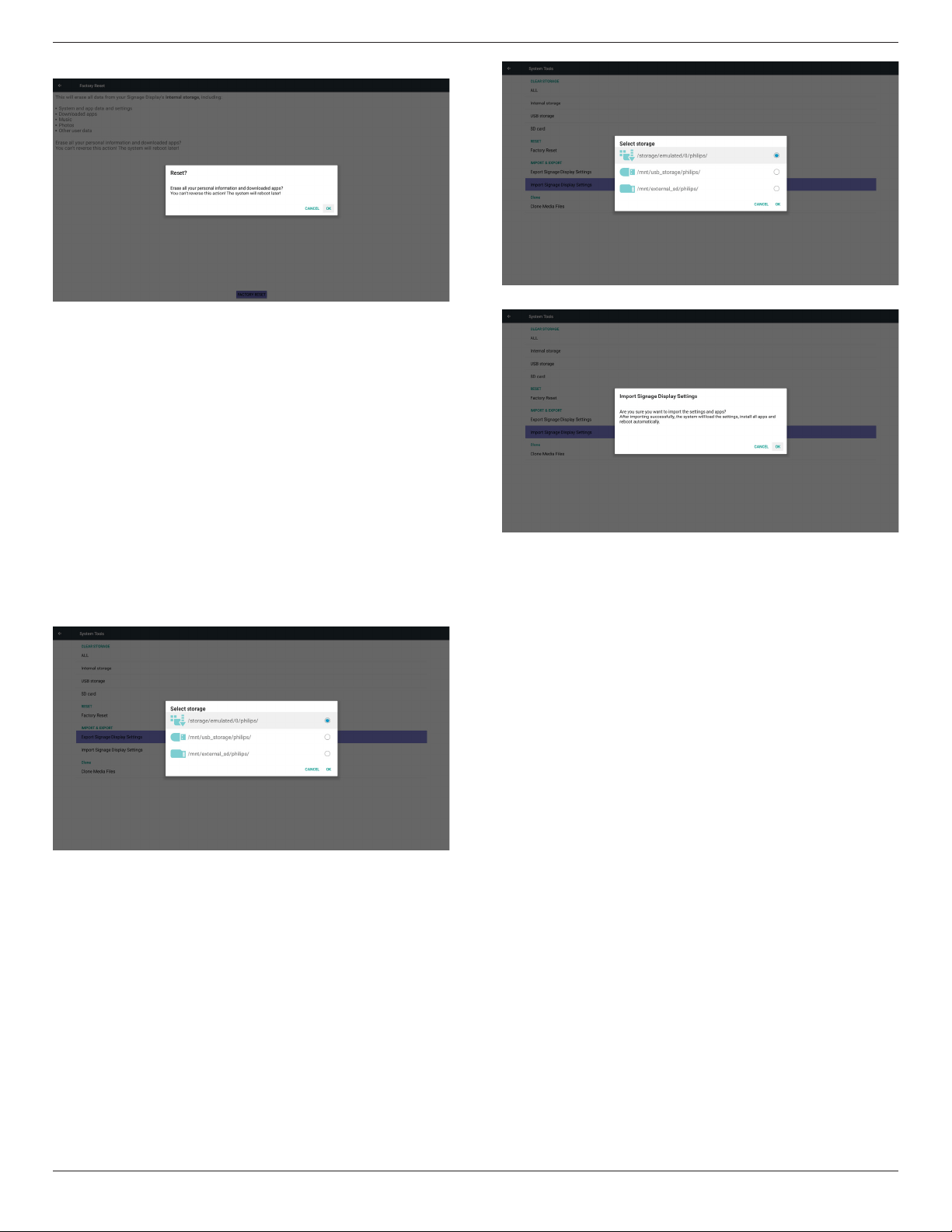
65BDL3050Q
34
Press OK to execute Reset function automatically
.
5.6.3. Import & Export
The function of Import & Export PD settins.
Notes.
(1) Settings.db (Saved le name: settings.db)
(2) Will save to Philips folder in storage
5.6.3.1. Export Signage Display Settings
Will export to Philips folder under USB or SD card
(1) Export settings.db. Include OSD setting, Android settings but
“Signage Display Name” and “Boot Logo”
(2) Export 3
rd
party apk to Philips/app/
Note:
If no Philips folder exists in USB or SD card, it will be created
automatically.
List all available storage (internal/SD/USB)
5.6.3.2. Import Signage Display Settings
Import settings.db from Philips folder under USB or SD card.
(1) Import settings.db. Include OSD setting, Android settings but
“Signage Display Name” and “Boot Logo”
(2) Auto install 3
rd
party apk from Philips/app/
List all available storage (Internal/SD/USB)
Show notication dialog before database import
5.7. Clone Media File
Clone media le from Internal, SD or USB Philips folder.
1. The cloned folder name under Philips folder
(1) philips/photo
(2) philips/music
(3) philips/video
(4) philips/cms
(5) philips/pdf
(6) philips/browser
2. The cloned le extension name is “.cms”)
Clone Source
(1) Internal storage
(a) check FTP
(b) check /Philips/
(2) SD / USB
Files under root
Target Location
(1) Internal storage
Save to /Philips/
(2) SD / USB
Save to root
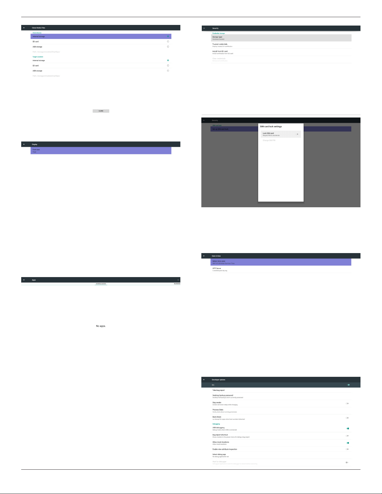
65BDL3050Q
35
5.8. Display
User can modify the font size, can choose: Small/Normal/Large/Huge
5.9. Apps
Display applications information.
Note
(1) User options key on RCU to show setting option.
5.10. Security
(1) Credential storage
Control panel of certicates
5.11. Date & time
Via Scalar OSD menu to control Auto Time On/Off.
Note:
Add new NTP server to display current server IP
.
5.12. Developer options
Android developer options. For more information please visit
https://developer.android.com/index.html
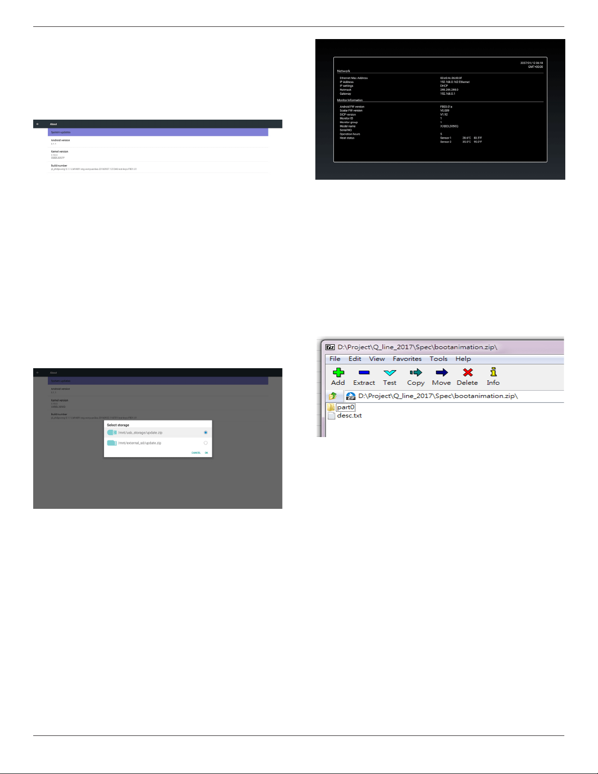
65BDL3050Q
36
5.13. About
Main info in About:
(1) System updates
(2) Android version
(3) Kernel version
(4) Build number
5.13.1. System updates
Will automatically search update.zip in USB.
Will be shown in list for user selection if found
Note:
(1) Only support Android Full image.
(2) le name should be update.zip.
(3) the le should be located in root of storage.
After select update.zip le, PD will restart and start to update.
5.14. Supplementary
5.14.1. Quick Info
You can press “Info + 77” to startup quick info.
Quick info will show “Network” and “Monitor Information”, as below:
Note:
Operation hours : It is updated every minute.
Heat status : It is updated every 5 seconds.
5.14.2. How to custom an Android boot
animation?
1. Overview
The Android boot animation is used script to load PNG les when
the device boots. It is contained within an uncompressed zip le called
bootanimation.zip.
2. Inside the bootanimation.zip le
The bootanimation.zip as follow:
• The image folder (Contains PNG images named in incremental
numbers)
• The desc.txt le
(1) The image folder
These contain PNG images named in numbers, starting from
something like 0000.png or 0001.png and proceeding with
increments of 1. There has to be at least one folder and there is no
known upper limit to the number of folders.
(2) The desc.txt le
This le denes how the images in the folder(s) are displayed during
the boot animation, in the following format:
- Width Height Frame-rate
- mode Loop delay-time Folder1
- mode Loop delay-time Folder2
An example of a desc.txt le is:
- 1920 1080 30
- p 1 0 part0
- p 0 0 part1
a. The rst line
1920 and 1080 dene the width and height of the screen
resolution.
30 is the frame rate in fps (frames per second) i.e. number of
images to display per second.
b. The second and third lines have a same format.
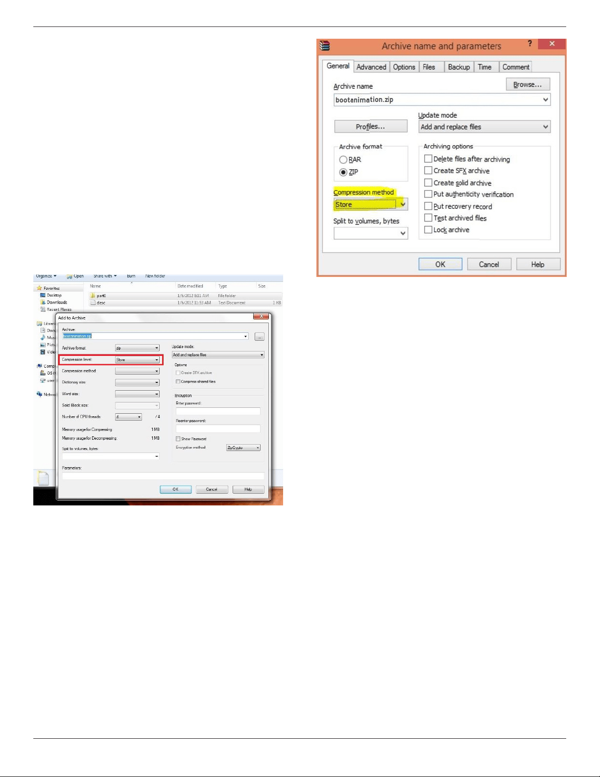
65BDL3050Q
37
The rst ‘p’ denes play mode is immediately stop playing when
boot complete.
The number after ‘p’ denes repeat mode
- specifying 0 would make the part loop indenitely till the
device has boot complete.
- specifying 1 would make the part playback once.
The next number denes the delay time(ms). For example, if set
10, when all image les has been playback, system will delay 10ms.
The part0 and part1 are image folder name.
The above example, the boot animation will play at a resolution of 1920
by 1080 pixels, at a frame rate of 30 fps, starting with the contents of
part0 folder and after playing them in one loop, switching to contents
of part1 folder and playing them continuously till the device boot
complete.
3. Zip le:
Select everything (image folders and desc.txt) inside the Bootanimation
folder and zip them into a new uncompressedziparchive using your
favorite compression utility like 7zip or WinRAR and so on.
If using 7zip, set compression level to “Store”
If using WinRAR, set “Compression method” to “Store”
or else bootanimation WON’T work
4. Apply the custom bootanimation
Procedure:
(1). Put your custom bootanimztion.zip le into external SD card or
USB and plug into Phillips PD platform.
(2.) Make sure the Logo option is enabled.
Press Home key on RCU: OSD menu -> Conguration 2 -> Logo
-> set “User”
(3.) Press combination key “Home + 1888” on RCU to go to Admin
mode:
Settings -> Signage Display -> GENERAL SETTINGS -> Boot Logo
(4). The system will nd the bootanimation.zip in external SD card or
USB automatically and copy it to /data/local
(5.) Once step 1~4 has been done, restart the system. The new
customized boot animation should be displayed during boot time.
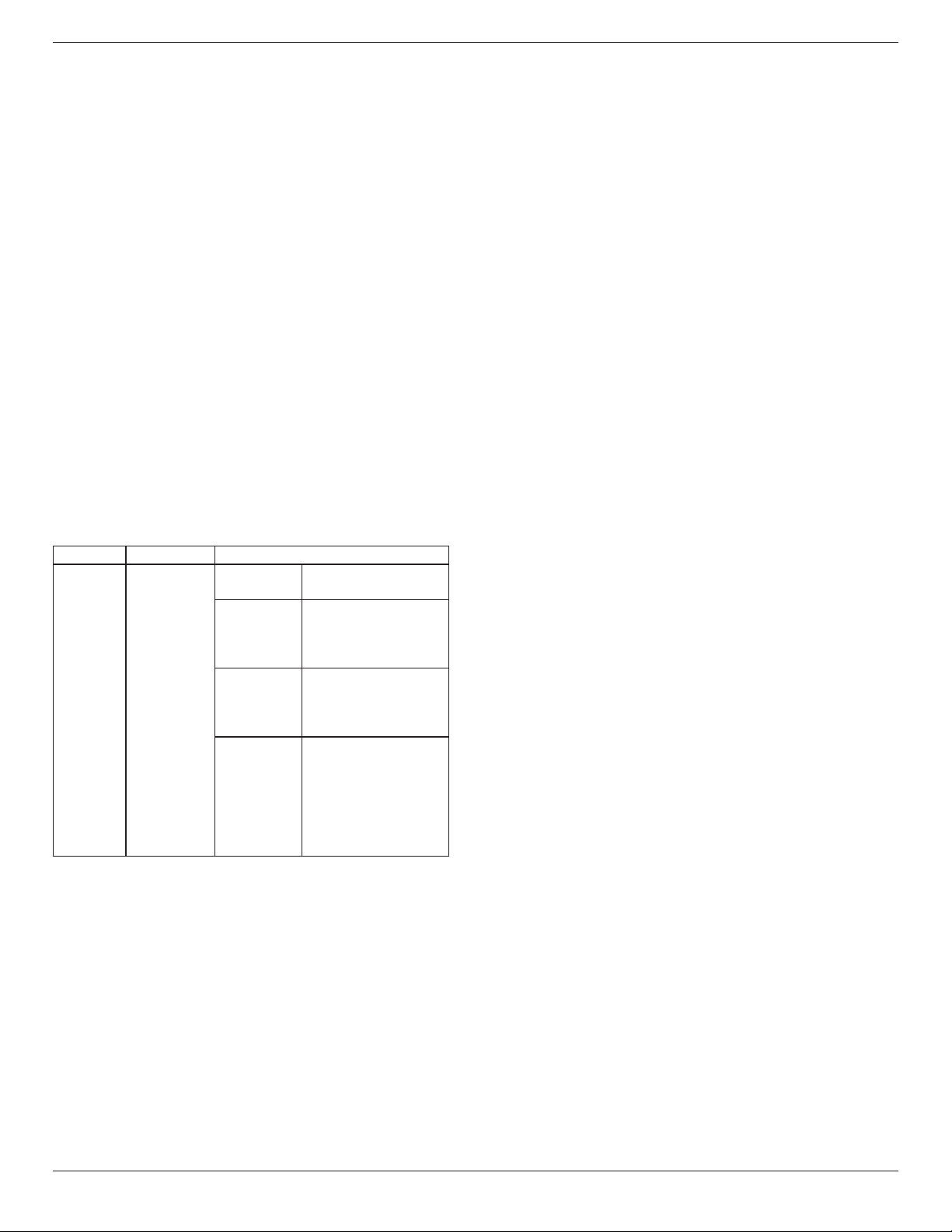
65BDL3050Q
38
5.14.3. How to Install Android app?
There are 3 ways to install your own android app.
(a) Via File Manager in Admin Mode
1. If you have apk already
1.1 copy your apk to USB disk or SD card, and then plug them
into Philips Android Signage Display.
1.2 Go to Admin Mode > Apps > File Manager
1.3 Using File Manager and nd out your apk and then you can
install. Just press “ok” on the selected apk.
2. Download apk by Chromium browser, and then go to <internal
storage path>/Download/ by File Manager.
2.1 The rest of steps is the same as above. Please note, each model
may have different <internal storage path>.
(b) Via Adb Shell
1. Make sure that your PC can connect to Philips Android Signage
Display using adb.
2. Prepare your apk in a folder(for example, C:\apkfolder) on PC.
3. Execute the following instruction by command line tool.
C:\apkfolder> adb install -r apk_name.apk
(c) Via Customized Intent
1. If you develop an apk which can download any android app, then
your apk can issue a customized intent.
2. Giving the apk name and the path it was stored. The system will
help you to install by program.
Description Intent Parameters
Sw Update
php.intent.
action.
UPDATE_APK
lePath
The absolute le path
including the le name.
Keep
Indicate that you want
to keep the le or not
after updating. The default
value is false.
packageName
The target package
you want to launch
automatically after
updating.
activityName
The target activity
you want to launch
automatically after
updating. But if current
top activity is not
activityName, nothing
happened.
For example,
Intent intent = new Intent();
intent.setAction(“php.intent.action.UPDATE_APK”);
intent.putExtra(“lePath”, “/sdcard/Download/apk_name.apk”);
intent.putExtra(“keep”, true);
intent.putExtra(“packageName”, “com.example.apk_name”);
intent.putExtra(“activityName”, “com.example.apk_name.MainActivity”);
sendBroadcast(intent);
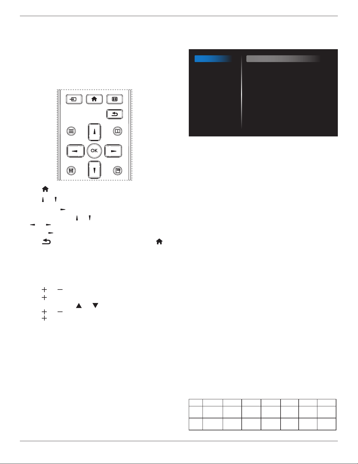
65BDL3050Q
39
6. OSD Menu
An overall view of the On-Screen Display (OSD) structure is shown
below. You can use it as a reference for further adjusting your display.
6.1. Navigating the OSD Menu
6.1.1. Navigating the OSD menu using the
remote control
FORMAT
SOURCE
INFOLIST
OPTIONSADJUST
1. Press [ ] button on the remote control to display the OSD menu.
2. Press [ ] or [ ] button to choose the item you want to adjust.
3. Press [OK] or [ ] button to enter the submenu.
4. In the submenu, press [ ] or [ ] button to toggle among items, press
[ ]
or [ ] button to adjust settings. If there is a submenu, press
[OK] or [ ] button to enter the submenu.
5. Press [ ] button to return to the previous menu, or press [ ]
button to exit the OSD menu.
6.1.2. Navigating the OSD menu using the
display’s control buttons
1. Press [MENU] button to display the OSD menu.
2. Press [ ] or [ ] button to choose the item you want to adjust.
3. Press [ ] button to enter the submenu.
4. In the submenu, press [ ] or [ ] button to toggle among items,
press [ ] or [ ] button to adjust settings. If there is a submenu,
press [ ] button to enter the submenu.
5. Press [MENU] button to return to the previous menu, or press
[MENU] button several times to exit the OSD menu.
6.2. OSD Menu Overview
6.2.1. Picture menu
Picture
Screen
Audio
Configuration 1
Configuration 2
Advanced option
Brightness
Contrast
Sharpness
Black level
Tint
Color
Noise reduction
Gamma selection
Color temperature
Color control
Smart power
Overscan
90
50
20
50
50
55
Medium
Native
Native
Action
Off
Off
Brightness(Picture)
Adjust the overall image and background screen brightness(backlight).
Contrast
Adjust the image contrast ratio for the input signal.
Sharpness
This function is digitally capable to keep crisp image at any timings.
It is adjustable to get a distinct image or a soft one as you prefer and set
independently for each picture mode.
Black level
Adjust the image brightness for the background.
NOTE: sRGB picture mode is standard and cannot be changed.
Tint (Hue)
Adjust the tint of the screen.
Press + button the esh tone color becomes greenish.
Press - button the esh tone color becomes purplish.
NOTE: VIDEO mode only.
Color(Saturation)
Adjust the color of the screen.
Press + button to increase color depth.
Press - button to decrease color depth.
NOTE: VIDEO mode only
Noise Reduction
Adjust the noise reduction level.
Gamma selection
Select a display gamma. It’s refer to the brightness performance curve of
signal input. Choose from {Native} / {2.2} / {2.4} / {s gamma} / {D-image}.
NOTE: sRGB picture mode is standard and cannot be changed.
Color temperature
It is used to adjust the color temperature.
The image becomes reddish as the color temperature decreases, and
becomes bluish as the color temperature increases.
CCT
10000º K 9300 º K 7500 º K 6500 º K 5000 º K 4000 º K 3000 º K
X
0.279 ±
0.030
0.283 ±
0.030
0.299 ±
0.030
0.313 ±
0.030
0.346±
0.030
0.382±
0.030
0.440±
0.030
Y
0.292 ±
0.030
0.298 ±
0.030
0.315 ±
0.030
0.329 ±
0.030
0.359±
0.030
0.384±
0.030
0.403±
0.030
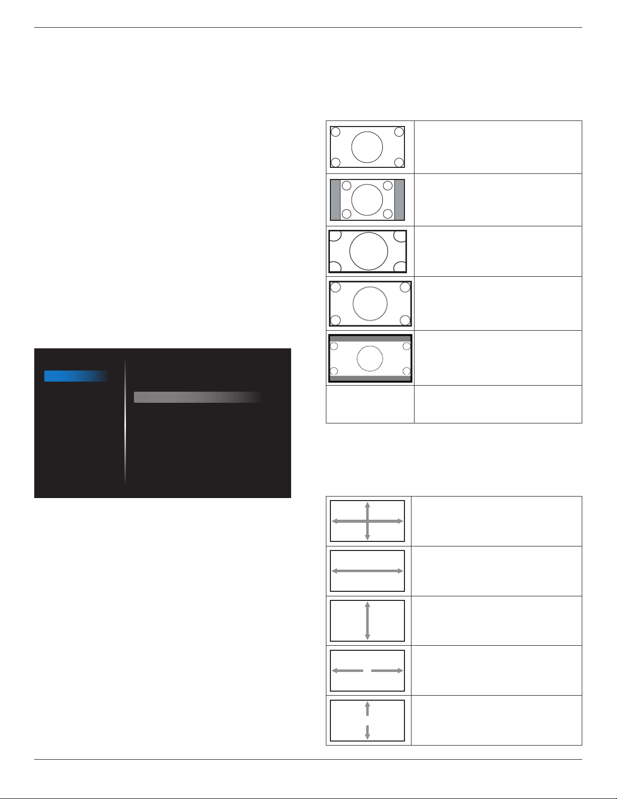
65BDL3050Q
40
Color control
The color levels of red, green, and blue are adjusted by the color bars.
R: Red gain, G: Green gain, B: Blue gain.
Smart power
Smart Power control is not relative to brightness control:
1. Initial setting Brigthness
70 (in the range from 0-100)
Power consumption 70% of maximum power consumption
2. Smart Power
OFF: no adaptation
MEDIUM: 80% of power consumption relative to current settings
HIGH: 65% of power consumption relative to current settings
Overscan
Change the display area of the image.
ON: Set to display area about 95%.
OFF: Set to display area about 100%.
Picture reset
Reset all settings in the Picture menu.
Select “Yes” and press “SET” button to restore to factory preset data.
Press “EXIT” button to cancel and then return to the previous menu.
6.2.2. Screen menu
Picture
Screen
Audio
Configuration 1
Configuration 2
Advanced option
H position
V position
Clock
Zoom mode
Custom zoom
Auto adjust
Screen reset
50
50
97
Full
Action
Action
Action
H position
Control Horizontal Image position within the display area of the LCD.
Press + button to move screen to right.
Press - button to move screen to left.
NOTE: VGA input only.
V position
Control Vertical Image position within the display area of the LCD.
Press + button to move screen to up.
Press - button to move screen to down.
NOTE: VGA input only.
Clock
Press + button to expand the width of the image on the screen the
right.
Press - button to narrow the width of the image on the screen the left.
NOTE: VGA input only.
Zoom mode
HDMI, DP, VGA, OPS: {Full}/{4:3}/{Real}/{21:9}/{Custom}.
Playing media in Media Player : {Full}/{4:3}/{Real}/{21:9}
There are no function when BROWSER, CMND & Play, PDF Player, PDF
Player, Custom and Media Player UI and Android UI
Zoom Mode will be “Full” when tiling
Full
This mode restores the correct proportions
of pictures transmitted in 16:9 using the full
screen display.
4:3
The picture is reproduced in 4:3 format and
a black band is displayed on either side of the
picture.
Real
This mode displays the image pixel-by-pixel
on screen without scaling the original image
size.
16:9
The picture is reproduced in 16:9 format and
a black band at the top and bottom.
21:9
The picture is reproduced in 21:9 format and
a black band at the top and bottom.
Custom
Choose to apply the custom zoom settings in
the Custom Zoom submenu.
Custom zoom
You can use this function to further customize the zoom settings to suit
the image you want to display.
NOTE: This item is functional only when the {Zoommode} is set to
{Custom}.
Zoom
Expands the horizontal and vertical sizes of the
image simultaneously.
H zoom
Expands the horizontal size of the image only.
V zoom
Expands the vertical size of the image only.
H position
Moves the horizontal position of the image left
or right.
V position
Moves the vertical position of the image up or
down.

65BDL3050Q
41
Auto adjust
Press “Set” to detect and adjust H position, V position, Clock, Phase
automatically.
NOTE: VGA input only.
Screen reset
Reset all settings in the Screen menu to factory preset values.
6.2.3. Audio menu
Picture
Screen
Audio
Configuration 1
Configuration 2
Advanced option
Balance
Treble
Bass
Volume
Audio Out (Line Out)
Maximum Volume
Minimum Volume
Mute
Audio source
Audio reset
Audio Out Sync
50
50
50
30
30
100
0
Off
Digital
Action
Off
Balance
Adjust to emphasize left or right audio output balance.
Treble
Adjust to increase or decrease higher-pitched sounds.
Bass
Adjust to increase or decrease lower-pitched sounds.
Volume
Adjust to increase or decrease the audio output level.
Audio out (line out)
Adjust to increase or decrease line out output level.
Maximum volume
Adjust your own limitation for the maximum volume setting. This stops
the volume from being playing at too loud a level.
Minimum volume
Adjust your own limitation for the minimum volume setting.
Mute
Turn the mute function on/off.
Audio source
Select the audio input source. There are no audio output when no video
signal.
Analog: audio from audio input
Digital : audio from HDMI/DVI audio.
Audio reset
Reset all settings in the Audio menu to factory preset values.
Audio Out Sync
Enable/disable audio out (line out) volume adjustability to sync with
internal speakers.
6.2.4. Configuration1 menu
Picture
Screen
Audio
Configuration 1
Configuration 2
Advanced option
Switch on state
Panel saving
RS232 routing
Boot on source
WOL
Configuration1 reset
Factory reset
Force on
Action
RS232
Action
Off
Action
Action
Switch on state
Select the display status used for the next time you connect the power
cord.
• {Poweroff} - The display will remain off when the power cord is
connected to a wall outlet.
• {Forced on} - The display will turn on when the power cord is
connected to a wall outlet.
• {Last status} - The display will return to the previous power status
(on/off/standby) when removing and replacing the power cord.
Panel saving
Choose to enable the panel saving functions and thus reduce the risk of
“image persistence” or “ghost-imaging”.
• {Brightness} - Select {On} and the image brightness will be reduced
to an appropriate level. The Brightness setting in the Picture menu
will be unavailable when selected.
• {Pixel shift} - Select the time interval ({Auto}/{10~900} Seconds/
{Off}) for the display to slightly expand the image size and shift
the position of pixels in four directions (up, down, left, or right).
Activating Pixel Shift will disable H Position, V Position and Zoom
Mode in the Screen Menu.
Note: Only support external input source (HDMI, VGA, DP, OPS).
RS232-Routing
Select the network control port.
Choose from: {RS232}/{LAN->RS232} / {CardOPSRS232(OPS
modelonly)}.
Boot on source
Choose to select source when boot up.
Input: select input source when boot up.
Playlist: select playlist index for Media player, Browser, PDF player.
0: no play list. Same as switch source from OSD.1~7: playlist number.
No failover function, system will keep source even the source is no
signal input.
Wake on Lan (WOL)
Choose to turn on or off the wake on LAN function.
Choose from : {Off} / { On}
Conguration1 reset
Reset all settings in Conguration1 menu to the factory preset values.

65BDL3050Q
42
Factory reset
Reset all settings in the OSD menus of {Picture}, {Screen}, {Audio},
{Conguration1}, {Conguration2}, and {Advanced option} to the
factory preset values.
Android settings will also reset when factory reset.
Press [
]
or [ ] button to select {Reset}, and press [OK] button to
do the reset.
Factory reset
CANCEL Reset
6.2.5. Configuration2 menu
Picture
Screen
Audio
Configuration 1
Configuration 2
Advanced option
OSD turn off
OSD H position
OSD V position
Information OSD
Logo
Monitor ID
Heat status
Monitor information
HDMI Version
Configuration2 reset
45
50
50
10
On
Action
24.21°C 75.57°F
Action
Action
OSD turn off
Set the period of time the OSD (on-screen display) menu stays on the
screen.
The options are: {
Off,5~120} seconds.
*{Off} does not disappear automatically.
OSD H-position
Adjust the horizontal position of the OSD menu.
OSD V-position
Adjust the vertical position of the OSD menu.
Information OSD
Set the period of time the information OSD is displayed on the upper
right corner of the screen. The information OSD will display when input
signal is changed.
The information OSD will remain on the screen with {Off} selection.
The options are: {1 ~ 60} seconds.
Logo
Choose to enable or disable the picture of Logo when turn on your
display.
The options are:
• {Off}
• {On} (Default)
• {User}
1. If Logo set to ON, both scalar Philips logo and android animation
Philips logo will show.
2. If Log set to OFF, neither scalar Philips logo nor android animation
logo will not show.
3. If Logo set to USER, custom logo option in android is not set, then
there will be no boot logo when power on.
4. If Logo set to USER, custom logo option in android is set, there will
be only custom logo when power up.
Monitor ID
Set the ID number for controlling the display via the RS232C
connection. Each display must have a unique ID number when multiple
sets of this display are connected. Monitor ID number range is between
1 to 255.
The option are: {Monitor group}
Monitor ID
Monitor ID
Monitor group
1
1
• {Monitor group}
The options are: {Off} / {1-254}
• {Off} – {Monitor group} are not supported.
• {1-254} – {Monitor group} are supported. The default setting is
1.
1 2
5 6
3
4
7 8
9 10 11 12
13 14 15 16
Heat status
This function allows you to check the thermal status at any time.
Monitor information
Shows information about your display, including model number, serial
number, operating hours and software version.
Monitor information
Model name
Serial NO.
Operation hours
SW Version
XXBDL3050Q
N/A
0
FBXX.XX
HDMI Version
Set the HDMI version to 1.4 or 2.0, this setting is only valid on HDMI
input
Conguration2 reset
Reset all settings in Conguration2 menu to the factory preset values.
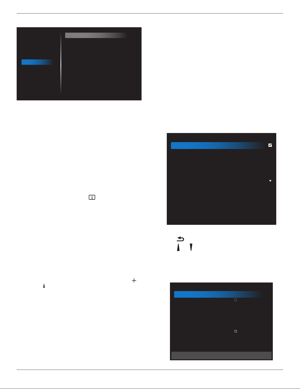
65BDL3050Q
43
6.2.6. Advanced option menu
Picture
Screen
Audio
Configuration 1
Configuration 2
Advanced option
IR control
Power LED Light
Keyboard control
Tiling
Off Timer
Date and time
Schedule
HDMI with One Wire
Language
OSD Transparency
Power Save
Advanced option reset
Unlock
On
Unlock
Action
Off
Action
Action
Off
English
Off
Mode 1
Action
IR control
Select the operation mode of the remote control when multiple
displays are connected via an RS232C connection.
• {Unlock} - All displays can be operated normally by the remote
control unit.
• {Primary} - Designate this display as the primary display for
remote control operation. Only this display can be operated by the
remote control. (In primary mode, IR key will always be processed
regardless the monitor id/group settings).
• {Secondary} - Designate this display as the secondary display. This
display can not be operated by the remote control, and will only
receive the control signal from the primary display via the RS232C
connection.
• {LockAll} / {LockallbutVolume} / {LockallbutPower} / {Lock
allexceptPWR&VOL}- Lock the remote control function of this
display. To unlock, press and hold the [ ] INFO button on the
remote control for 6 (six) seconds.
Power LED light
Choose to set power indicate LED on or off.
Choose {On} for normal use.
Keyboard control
Choose to enable or disable the display keyboard (control buttons)
function.
• {Unlock} - Enable the keyboard function.
• {LockAll} / {LockallbutVolume} / {LockallbutPower} / {Lockall
except PWR & VOL} - Disable the keyboard function.
NOTE: “Keyboard Control Lock Mode” This function completely
disables the access to all Keyboard Control functions. To
enable or disable the keyboard control lock, press both [ ]
and [ ] buttons and hold down continuously for more than 3
seconds.
Tiling
With this function you can create a single large-screen matrix (video
wall) that consists of up to 150 sets of this display (upto10-setsonthe
verticaland15-setsonthehorizontalsides). This function requires a
daisy-chain connection.
• Switchondelay: Set the power-on delaying time (in seconds). The
default option {Auto} allows a sequential powering-on for each
display by their ID number when multiple displays are connected.
The options are: {Off (0) / Auto(1) / 2-255}
• Brightness: {Normal}/{ACS}
• {Normal}: Adjust the overall image and background screen
brightness (backlight).
• {ACS}: Apply brightness value (backlight) which is adjusted by
MIC tool. The default value before adjustment is the same as
OSD brightness value, e.g., 70)
• Type: {Off} (Default)/{SW Tool}/{OSD Only}
• Source resolution: {Full HD}(Default)/ {4K}
• Hmonitors - Select the number of displays on the horizontal side.
• Vmonitors - Select the number of displays on the vertical side.
• Position - Select the position of this display in the screen matrix.
• Framecomp.- Choose to turn the frame compensation function
on or off. If selected {Yes}, the display will adjust the image to
compensate for the width of the display bezels in order to
accurately display the image.
NOTE: Doesn’t support screen format function in tiling using cascade
mode.
Off Timer
Set automatically power off time (in hours).
Date and time
Adjust the current date and time for the display’s internal clock.
Date and time
Auto Sync
Set date
Set time
Choose time zone
London, Dublin
GMT+1:00
NTP Server
Current date time
2.android.pool.ntp.org
2017/06/27 13:17:33
1. Press [OK] button to enter or choose
2. Press [ ] back button to return.
3. Press [ ]
or [ ] button to adjust them.
* Cannot set time to date after year 2037.
Schedule
This function allows you to program up to 7 (seven) different scheduled
time intervals for the display to activate.
Schedule
Schedule list
Enable
Start time
End time
Input
Playlist
Days of the week
Every week
1
Back SAVE
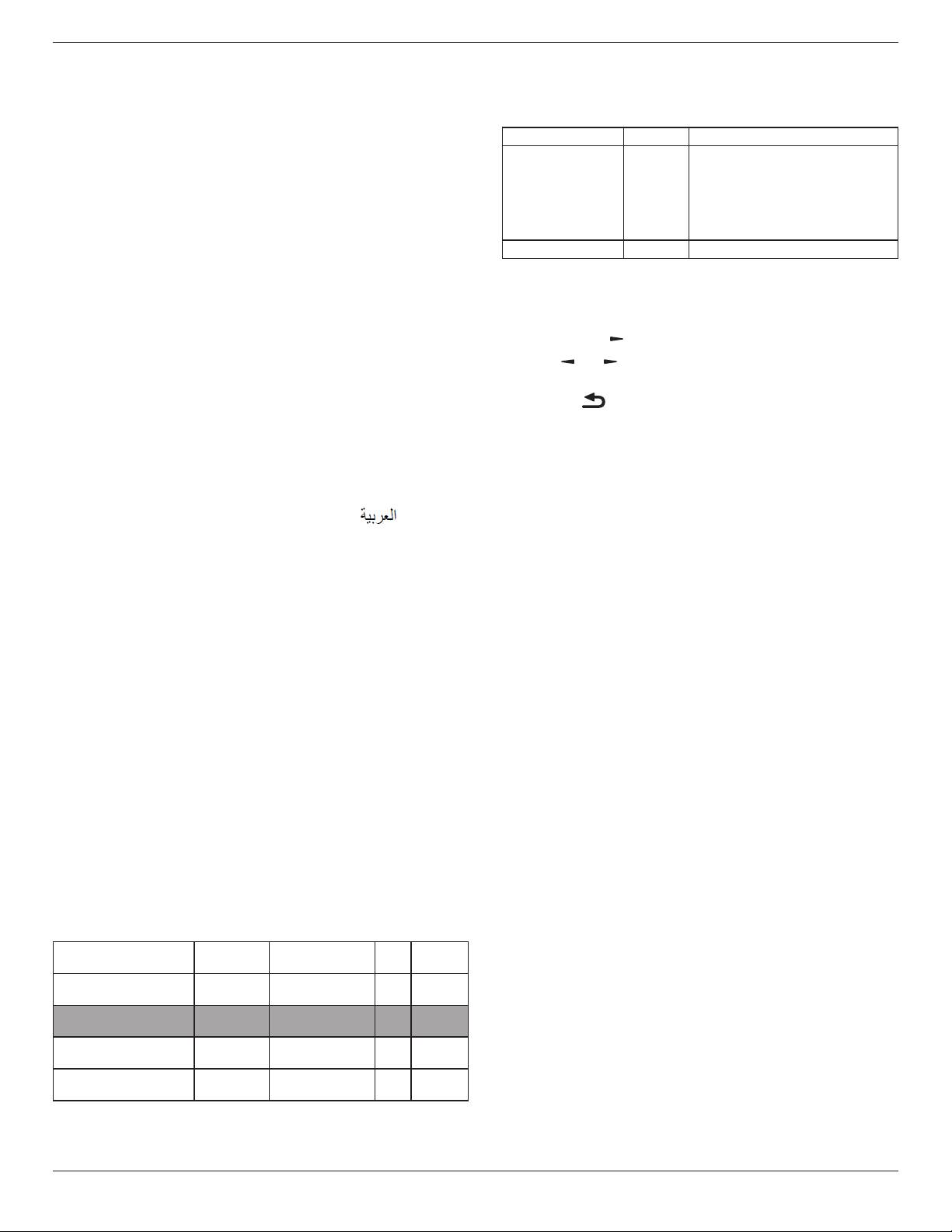
65BDL3050Q
44
• Schedule list: You can set 7 schedules.
• Enable: Enable/disable schedule. If set start/end time is conict or
empty, input is empty or time conict with other schedule list, you
cannot enable schedule.
• Starttime:Set start time.
• Endtime: Set end time.
• Input: Platform will go to this select source automatically after the
schedule on.
• Playlist: 1 - 7 : playback File1 - File7 of playlist automatically, only
media player, pdf player and browser can set.
• Daysoftheweek: Set Sunday, Monday, Tuesday, Wednesday,
Thursday, Friday, Saturday.
• Everyweek:Set lifecycle.
• Back:Does not change schedule data.
• Save: Save schedule data.
HDMI with One Wire
CEC control.
• {Off} - Disable CEC.(Default)
• {On} - Enable CEC.
Language
Select the language used in the OSD menu.
The options are: English/Deutsch/
简体中文
/Français/Italiano/Español/
Pyccкий/Polski/Türkçe/
繁體中文
/
日本語
/Português/ /Danish/
Svenska/Finnish/Norsk/Nederlands.
OSD Transparency
Adjust OSD transparency.
• {Off} - Transparency off.
• {1-100} - Transparency level 1-100.
Power Save
Mode 1 [TCP off, WOL on, auto off]
Mode 2 [TCP off, WOL on, auto on/off]
Mode 3 [TCP on, WOL off, auto on/off]
Mode 4 [TCP on, WOL off, no auto on/off]
Power save modes
Mode 1: DC off -> Power off. LED: Red.
Power Save -> Power off, LED: Red
Mode 2: DC off -> Power off, LED: Red.
Power Save -> Power Saving. LED: Orange. Can be wake up.
Mode 3: DC off -> Back light off, LED: Red
Power Save -> Back light off, LED: Orange. Can be wake up.
Mode 4: DC off -> Back light off, LED: Red
Power Save -> Will not enter power save mode. show “no signal” only.
RCU Power
Button Off
No Signal WoL Android
(ARM)
Mode 1 [TCP off, WOL on,
auto off]
DC OFF DC OFF V ARM OFF
Mode 2 [TCP off, WOL on,
auto on/off] (gary out)
DC OFF When signal is back,
system wake up
V ARM OFF
Mode 3 [TCP off, WOL off,
auto on/off]
Backlight OFF Backlight OFF X ARM OFF
Mode 4 [TCP off, WOL off,
no auto on/off]
Backlight OFF Backlight ON, show
no signal
X ARM OFF
* This product does not support Mode 2
Following table is the action for Android board with different power
mode.
DC off/on: press power button by RC
Power mode in OSD Mode 1/2 Mode 3/4
DC off shutdown 1. The current source APK(such
as MediaPlayer, Broswer, PDF or
SmartCMS) will be closed.
2. Android system will go to the
default black launcher.
DC on Boot up 1. Android system reboots
Advanced option reset
Reset all settings except {DateandTime} in the Advanced option menu
to factory preset values.
1. Press [OK] or [ ] button to enter the submenu.
2. Press [ ]
or [ ] button to select {Reset} and press the [OK]
button to restore settings to factory preset values.
3.
Press the [ ] button or select {Cancel} and press the [OK]
button to cancel and then return to the previous menu.
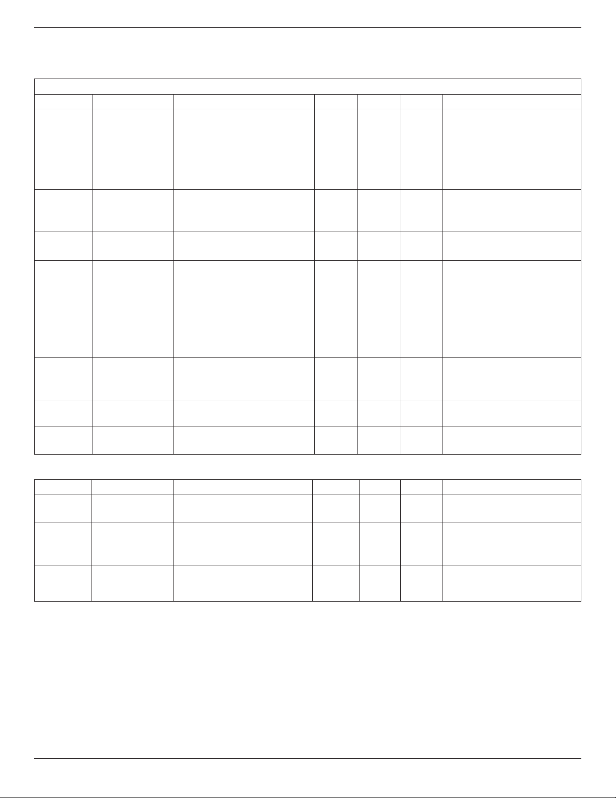
65BDL3050Q
45
7. Supported Media Formats
USB Multimedia Codec Formats
Video Decode
Type Video Codec Container Decode Encode Channel
Remark
MPEG1/2 MPEG1/2
MPEG program stream (.DAT, .VOB,
.MPG, .MPEG)
MPEG transport stream (.ts)
MP4 (.mp4)
AVI (.avi)
MKV (.mkv)
V
Max Resolution: 1080P@60fps
Max Bit Rats : 40Mbps
MPEG-4 MPEG4
MP4 (.mp4)
AVI (.avi)
MKV (.mkv)
V
Max Resolution: 1080P@60fps
Max Bit Rats : 40Mbps
H.263 H.263
FLV (.v)
AVI (.avi)
V
Max Resolution: 1080P@60fps
Max Bit Rats : 40Mbps
H.264 H.264
FLV (.v)
MP4 (.mp4)
MPEG transport stream (.ts)
ASF (.asf)
WMV (.wmv)
AVI (.avi)
MKV (.mkv)
V
Max Resolution: 1080P@60fps
Max Bit Rats : 135Mbps
4k2k@30fps
H.265 H.265
MP4 (.mp4)
MPEG transport stream (.ts)
MKV (.mkv)
V
Max Resolution: 4K2K@60fps
Max Bit Rats : 100Mbps
GOOGLE VP8 VP8 MKV (.mkv) WebM (.webm) V
Max Resolution: 1080P@30fps
Max Bit Rats : 20Mbps
Motion JPEG MJPEG
AVI (.avi)
MP4 (.mp4) MKV (.mkv)
V
Max Resolution: 1920*1080 @30fps
Max Bit Rats : 40Mbps
Audio Decode
Type Audio Codec Container Decode Encode Channel Remark
MPEG Audio
MPEG1/2/2.5 Audio
Layer1/2/3
MP3 V 2
Bit Rate: 8kbps~320Kbps
Sampling Rate: 16KHZ~48KHz
Windows
Media Audio
WMA Version 7, 8,
9,10 pro M0, 10Pro
M1,M10 Pro M2
Decode: WMA V 2
Bit Rate: 8kbps~768Kbps
Sampling Rate: 8KHZ~96(M10)KHz
Non-support LBR
AAC Audio
MAIN, ADIF ,ATDS
Header AAC-LC and
AAC-HE
File Format: AAC, M4A V 5.1
Bit Rate: N/A
Sampling Rate: 8KHZ~48KHz

65BDL3050Q
46
Image Decode
Type Image Codec Photo Decode Encode Channel Remark
JPEG JFIF le format 1.02 File Format: JPG, JPEG V
Max Resolution: 7000 x 7000
The limitation of max resolution depends on
DRAM
BMP BMP File Format: BMP V
Max Resolution: 15360 x 8640
The limitation of max resolution depends on
DRAM
PNG PNG File Format: PNG V
Max Resolution: 15360 x 8640
The limitation of max resolution depends on
DRAM
NOTES:
• Sound or video may not work if the contents have a standard bit rate/frame rate above the compatible Frame/sec listed in the table above.
• Video content with a Bit rate or Frame rate larger than the rate specied in the table above can cause choppy video during playback.
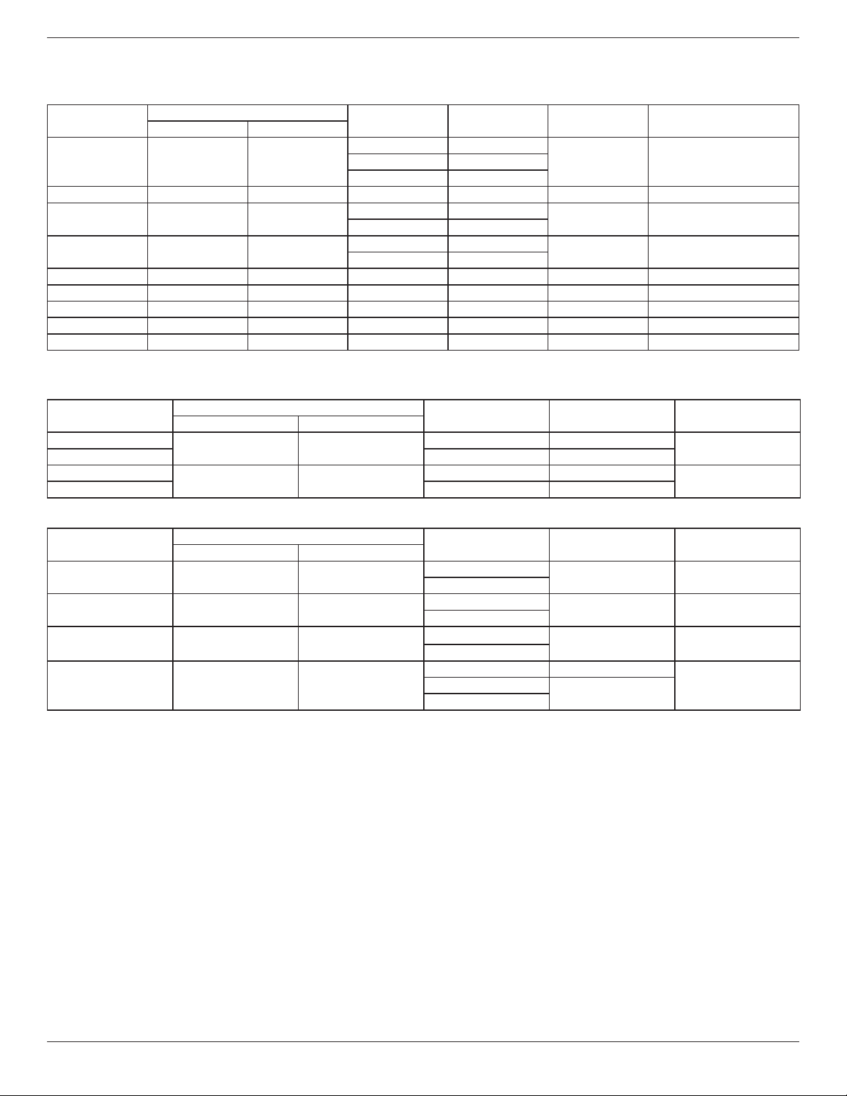
65BDL3050Q
47
8. Input Mode
VGA Resolution:
Standard
Resolution
Active Resolution
Refresh Rate Pixel Rate Aspect Ratio Stand for Mode
H Pixels V Lines
VGA 640 480
60 Hz 25.175 MHz
4:3 Video Graphic Array72 Hz 31.5 MHz
75 Hz 31.5 MHz
WVGA 720 400 70 Hz 33.75 MHz 16:9 Wide Video Graphic Array
SVGA 800 600
60 Hz 40 MHz
4:3 Super VGA
75 Hz 49.5 MHz
XGA 1024 768
60 Hz 65 MHz
4:3 Extended Graphic Array
75 Hz 78.75 MHz
WXGA 1280 768 60 Hz 79.5 MHz 5:3 Wide XGA
WXGA 1280 800 60 Hz 79.5 MHz 16:10 Wide XGA
SXGA 1280 1024 60 Hz 108 MHz 5:4 Super XGA
WXGA 1360 768 60 Hz 85.5 MHz 16:9 Wide XGA
HD1080 1920 1080 60 Hz 148.5 MHz 16:9 HD1080
Note: 1280x768/60Hz can be supported but not shown in EDID table.
SD Resolution:
Standard Resolution
Active Resolution
Refresh Rate Pixel Rate Aspect Ratio
H Pixels V Lines
480i
720 480
29.97 Hz 13.5 MHz
4:3
480p 59.94 Hz 27 MHz
576i
720 576
25 Hz 13.5 MHz
4:3
576p 50 Hz 27 MHz
HD Resolution:
Standard Resolution
Active Resolution
Refresh Rate Pixel Rate Aspect Ratio
H Pixels V Lines
720p 1280 720
50 Hz
74.25 MHz 16:9
60 Hz
1080i 1920 1080
25 Hz
74.25 MHz 16:9
30 Hz
1080p 1920 1080
50 Hz
148.5 MHz 16:9
60 Hz
2160p (HDMI only) 3840 2160
30 Hz 297 MHz
16:950 Hz
594 MHz
60 Hz
Note: OPS/DisplayPort support 3840x2160@30Hz.
• The PC text quality is optimum in HD 1080 mode (1920 x 1080, 60Hz).
• Your PC display screen might appear different depending on the manufacturer (and your particular version of Windows).
• Check your PC instruction book for information about connecting your PC to a display.
• If a vertical and horizontal frequency-select mode exists, select 60Hz (vertical) and 31.5KHz (horizontal). In some cases, abnormal signals (such as
stripes) might appear on the screen when the PC power is turned off (or if the PC is disconnected). If so, press the [INPUT] button to enter the
video mode. Also, make sure that the PC is connected.
• When horizontal synchronous signals seem irregular in RGB mode, check PC power saving mode or cable connections.
• The display settings table complies to the IBM/VESA standards, and based on the analog input.
• The DVI support mode is regarded as same to the PC support mode.
• The best timing for the vertical frequency to each mode is 60Hz.
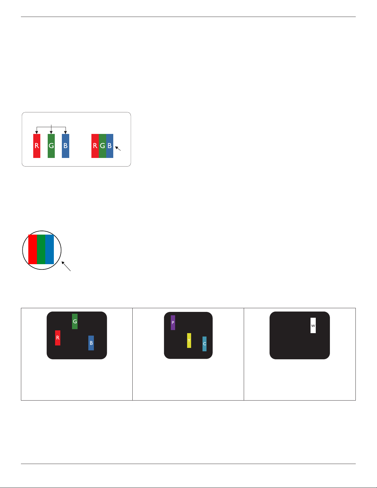
65BDL3050Q
48
9. Pixel Defect Policy
We strive to deliver the highest quality products and use some of the industry’s most advanced manufacturing processes whilst practicing stringent quality
control. However, pixel or sub-pixel defects on the PDP / TFT panels used in Plasma- & LCD- displays are sometimes unavoidable. No manufacturer can
guarantee that all panels will be free from pixel defects, but Philips guarantees that any Plasma- & LCD- displays with an unacceptable number of defects
will be repaired during the warranty period in line with your local guarantee conditions.
This notice explains the different types of pixel defects and denes the acceptable defect level for the LCD screen. In order to qualify for repair under
warranty, the number of pixel defects must exceed a certain level as shown in the reference table. If the LCD screen is within specication a warranty
exchange / claim back will be refused. Additionally, because some types or combinations of pixel defects are more noticeable than others, Philips sets even
higher quality standards for those.
9.1. Pixels and Sub-Pixels
subpixel
pixel
A pixel, or picture element, is composed of three sub-pixels in the primary colors of red, green and
blue. Many pixels together form an image. When all sub-pixels of a pixel are lit, the three colored
sub-pixels together appear as a single white pixel. When all are dark, the three colored sub-pixels
together appear as a single black pixel. Other combinations of lit and dark sub-pixels appear as
single pixels of other colors.
9.2. Types of Pixel Defects + Dot Definition
Pixel and sub-pixel defects appear on the screen in different ways. There are three categories of pixel defects and several types of sub-pixel defects within
each category.
Dot denition = What is a defective “Dot”? :
One or more defective, adjacent sub-pixel are dened as one “dot”. The no. of defective sub-pixels are not relevant to dene a defective dot. This means
that a defective dot can consist of one, two or three defective sub-pixels which can be dark or lit.
RR G B
One dot = One Pixel; consists of three sub-pixels of Red, Green, and Blue.
9.3. Bright Dot Defects
Bright dot defects appear as pixels or sub-pixels that are always lit or “on”. These are the examples of bright dot defects:
One lit red, green or blue sub pixel Two adjacent lit sub pixels:
Red + Blue = Purple
Red + Green = Yellow
Green + Blue = Cyan (Light Blue)
Three adjacent lit sub pixels (one white pixel)

65BDL3050Q
49
9.4. Dark Dot Defects
Black dot defects appear as pixels or sub-pixels that are always dark or “off”. These are the examples of black dot defects:
One dark dot Two adjacent dark dots = 1 pair of dark dots Two dark dots, specications denes the
minimum distance between dark dots
9.5. Proximity of Pixel Defects
Because pixel and sub-pixels defects of the same type that are nearby one another may be more noticeable, Philips also species tolerances for the
proximity of pixel defects. In the table below you can nd specications about:
• Allowed amount of adjacent dark dots = (adjacent dark dots =1 pair of dark dots)
• Minimum distance between dark dots
• Total no. of all defective dots
9.6. Pixel Defect Tolerances
In order to qualify for repair due to pixel defects during the warranty period, a PDP / TFT panel in a Philips Plasma / LCD- display must have pixel or sub-
pixel defects exceeding the tolerances listed in the following table.
BRIGHT DOT EFFECT ACCEPTABLE LEVEL
1 lit sub pixel 2
BLACK DOT EFFECT ACCEPTABLE LEVEL
1 dark sub pixel 10
TOTAL DOT DEFECTS OF ALL TYPES 12
NOTE: * 1 or 2 adjacent sub pixel defects = 1 dot defect
9.7. MURA
Dark spots or patches may occasionally appear on some liquid crystal display (LCD) panels. This is known within the industry as Mura, which is a Japanese
term for “unevenness.” It is used to describe an irregular pattern or area in which uneven screen uniformity appears under certain conditions. Mura is a
result of the deterioration of the liquid crystal alignment layer and is most commonly caused by long-term operation under high ambient temperatures. It
is an industry- wide phenomenon and Mura is not repairable. It is also not covered by our warranty terms.
Mura has been around since the introduction of LCD technology and with screens getting bigger and in operation 24/7, many displays are running in low
light conditions. This all adds to the possibility of Mura affecting displays.
HOW TO SPOT MURA
There are many symptoms of Mura and also multiple causes. Several of these are listed below:
• Impurities or foreign particles in the crystal matrix
• Uneven distribution of LCD matrix during manufacturing
• Non-uniform luminance distribution of the backlight
• Panel assembly induced stress
• Flaws within the LCD cells
• Thermal induced stress - high temperature operation over long periods of time
HOW TO AVOID MURA
Although we can not guarantee the complete eradication of Mura every time, in general the appearance of Mura can be minimized by these methods:
• Lower the backlight brightness
• Use a screen saver
• Reduce the ambient temperature around the unit

65BDL3050Q
50
10. Cleaning and Troubleshooting
10.1. Cleaning
Caution When Using the Display
• Do not bring your hands, face or objects close to the ventilation holes of the display. The top of the display is usually very hot due to the high
temperature of exhaust air being released through the ventilation holes. Burns or personal injuries may occur if any body parts are brought too
close. Placing any object near the top of the display could also result in heat related damage to the object as well as the display itself.
• Be sure to disconnect all cables before moving the display. Moving the display with its cables attached may damage the cables and thus cause re
or electric shock.
• Disconnect the power plug from the wall outlet as a safety precaution before carrying out any type of cleaning or maintenance procedure.
Front Panel Cleaning Instructions
• The front of the display has been specially treated. Wipe the surface gently using only a cleaning cloth or a soft, lint-free cloth.
• If the surface becomes dirty, soak a soft, lint-free cloth in a mild detergent solution. Wring the cloth to remove excess liquid. Wipe the surface of
the display to remove dirt. Then use a dry cloth of the same type to dry.
• Do not scratch or hit the surface of the panel with ngers or hard objects of any kind.
• Do not use volatile substances such as insert sprays, solvents and thinners.
Cabinet Cleaning Instructions
• If the cabinet becomes dirty, wipe the cabinet with a soft, dry cloth.
• If the cabinet is extremely dirty, soak a lint-free cloth in a mild detergent solution. Wring the cloth to remove as much moisture as possible. Wipe
the cabinet. Use another dry cloth to wipe over until the surface is dry.
• Do not allow any water or detergent to come into contact with the surface of the display. If water or moisture gets inside the unit, operating
problems, electrical and shock hazards may result.
• Do not scratch or hit the cabinet with ngers or hard objects of any kind.
• Do not use volatile substances such as insert sprays, solvents and thinners on the cabinet.
• Do not place anything made from rubber or PVC near the cabinet for any extended periods of time.

65BDL3050Q
51
10.2. Troubleshooting
Symptom PossibleCause Remedy
Nopictureisdisplayed 1. The power cord is disconnected.
2. The main power switch on the back of the
display is not switched on.
3. The selected input has no connection.
4. The display is in standby mode.
1. Plug in the power cord.
2. Make sure the power switch is switched on.
3. Connect a signal connection to the display.
Interferencedisplayedonthedisplayoraudible
noise is heard
Caused by surrounding electrical appliances or
uorescent lights.
Move the display to another location to see is the
interference is reduced.
Colorisabnormal The signal cable is not connected properly. Make sure that the signal cable is attached rmly
to the back of the display.
Pictureisdistortedwithabnormalpatterns 1. The signal cable is not connected properly.
2. The input signal is beyond the capabilities of
the display.
1. Make sure that the signal cable is attached
rmly.
2. Check the video signal source to see if it
is beyond the range of the display. Please
verify its specications with this display’s
specication section.
Displayimagedoesn’tllupthefullsizeofthe
screen
1. The zoom mode is not set correctly.
2. Scan Mode may be set incorrectly to
underscan.
3. If the image exceeds the screen size, Scan
Mode may need to be set to Underscan.
Use the Zoom mode or Custom zoom function
in the Screen menu to ne tune display geometry
and time frequency parameter.
Canhearsound,butnopicture Improperly connected source signal cable. Make sure that both video inputs and sound
inputs are correctly connected.
Canseepicturebutnosoundisheard 1. Improperly connected source signal cable.
2. Volume is turned all the way down.
3. {Mute} is turned on.
4. No external speaker connected.
1. Make sure that both video inputs and sound
inputs are correctly connected.
2. Press [ ] or [ ] button to hear sound.
3. Switch MUTE off by using the [ ] button.
4. Connect external speakers and adjust the
volume to a suitable level.
Somepictureelementsdonotlightup Some pixels of the display may not turn on. This display is manufactured using an extremely
high level of precision technology: however,
sometimes some pixels of the display may not
display. This is not a malfunction.
After-Imagescanstillbeseenonthedisplay
afterthedisplayispoweredoff.(Examples
ofstillpicturesincludelogos,videogames,
computerimages,andimagesdisplayedin4:3
normalmode)
A still picture is displayed for an over extended
period of time
Do not allow a still image to be displayed for
an extended period of time as this can cause a
permanent after-image to remain on the display.

65BDL3050Q
52
Howtosetupthesettingsinthemenuto
controlallthemonitorsatthesametimeand
individuallyviaRC?
Daisy chained by RS232 and no IR cable 1. The rst display sets as “Primary” on OSD
(Advanced option/IR control item), others set as
“Secondary”.
2. The setup OSD will show on Top-Left of display.
(Toggle MENU will show again if it disappear)
3. Default setting: ID NO: 0, GP NO: 0, this setting
can control all displays by IR.
The “+”, “-” can change “ID NO” to control
signal display by “Monitor ID”.
The “UP”, “DOWN” can change “GP NO” to
control multi-display by “Group ID”.
*The rst display always be controlled by IR.
HowistheRCworking? Daisy chain : no RS232 connected and IR cable No need setting, just to connect with IR cables
and control by IR.
*This way has out-of-synchronizm phenomenon.
Suggest to use above setting with RS-232 cable.
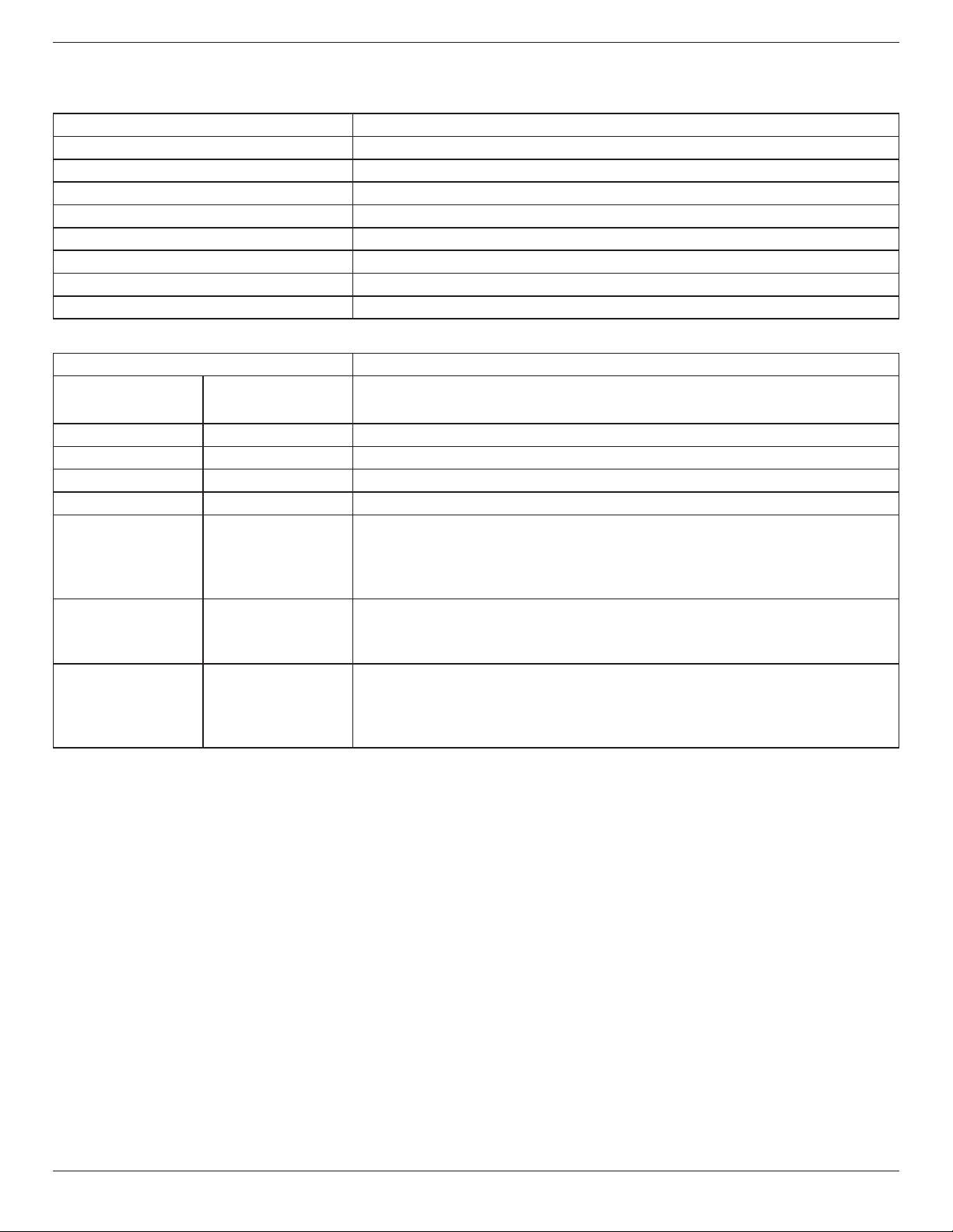
65BDL3050Q
53
11. Technical Specifications
Display:
Item Specications
Screen Size (Active Area) 163.9 cm / 64.5 inches
Aspect Ratio 16:9
Number of pixels 3840 (H) x 2160 (V)
Pixel pitch 0.372 (H) x 0.372 (V) [mm]
Displayable colors 10 bits(D), 1.07 Billion colors
Brightness (typical) 350 cd/m
2
Contrast ratio (typical) 4000:1
Viewing angle 178 degrees
In/Out Terminals:
Item Specications
Speaker Output Internal Speakers 10W (L) + 10W (R) [RMS]/8Ω
82 dB/W/M/160 Hz ~ 13 KHz
Audio Output RCA R/L x 1 0.5V [rms] (Normal) / 2 Channel (L+R)
Audio Input 3.5mm phone jack x 1 0.5V [rms] (Normal) / 2 Channel (L+R)
RS232C
2.5mm Phone jack x 2 RS232C in/RS232C out
RJ-45 RJ-45 Jack x 1 (8 pin) 10/100 LAN Port
HDMI Input HDMI Jack x 4
(Type A) (19 pin)
Digital RGB: TMDS (Video + Audio)
MAX:
Video - 720p, 1080p, 3840 x 2160/60 Hz
Audio - 48 KHz/ 2 Channel (L+R)
Supports LPCM only
VGA Input D-SUB jack (15pin) Digital RGB: TMDS (Video)
Analog RGB: 0.7V [p-p] (75Ω), H/CS/V: TTL (2.2kΩ),
MAX: 1920 x 1080/60 Hz (WUXGA)
Displayport in Displayport Jack x 1
(20 pin)
Digital RGB: TMDS (Video + Audio)
MAX:
Video - 720p, 1080p, 3840 x 2160/30 Hz
Audio - 48 KHz / 2 Channel (L+R)
Supports LPCM only
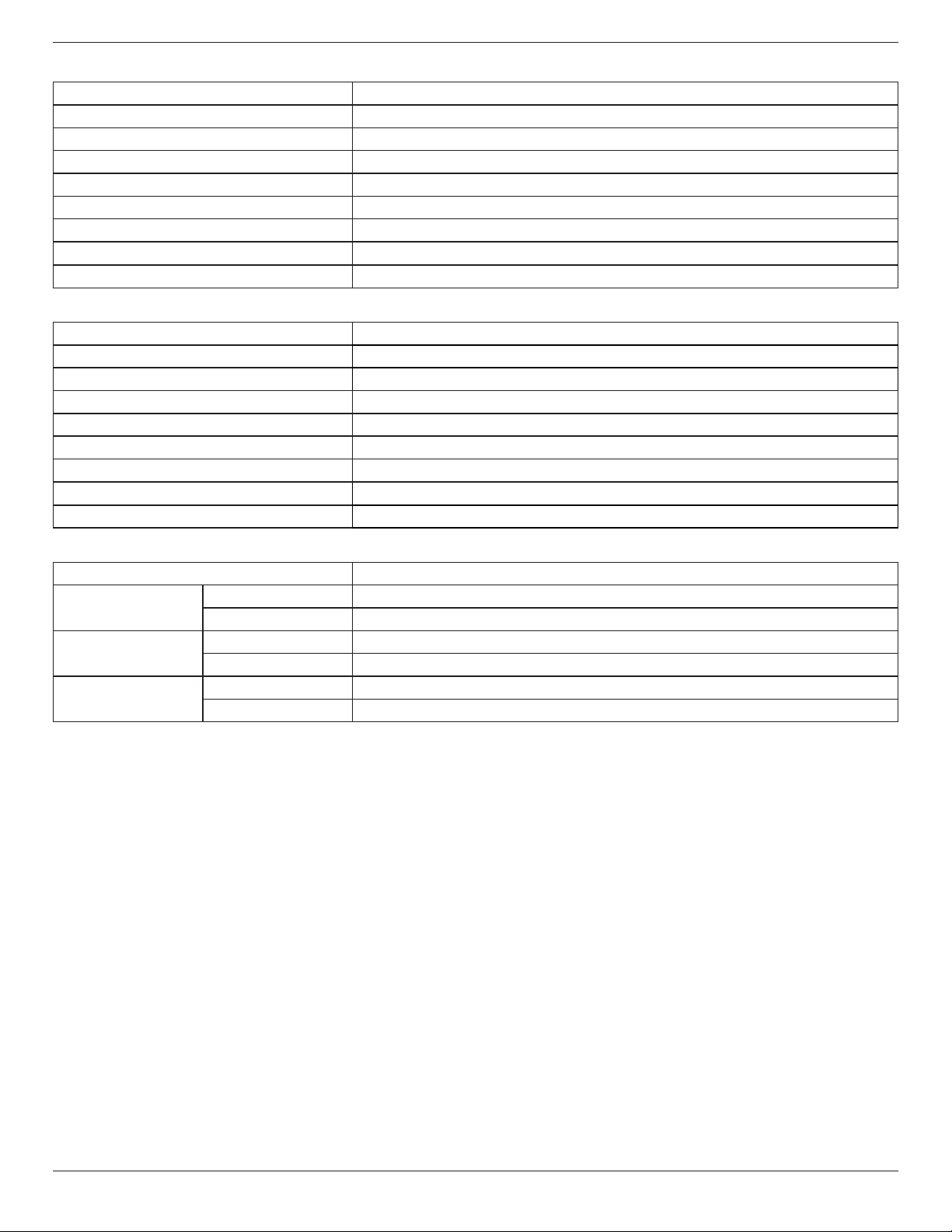
65BDL3050Q
54
General:
Item Specications
Power Input 100 - 240V~, 50 - 60Hz, 5.5A
Power Output 100 - 240V~, 50 - 60Hz, 2.5A
Power Consumption (Max) 295 W
Power Consumption (typ.) 165 W
Power Consumption (Standby & Off) <0.5 W
Dimensions (Without Stand) [W x H x D] 1458.7 x 834.7 x 81.6 mm
Weight (Without Stand) 24.8 Kg
Gross Weight (Without Stand) 39.3 Kg
Product Fiche :
Item Specications
Energy Efciency Class B
Visible Screen Size 163.9 cm / 64.5 inches
On Mode Power Consumption (W) 186 W
Annual Energy Consumption (kWh) 272 kWh
Standby Power Consumption (W) 0.50 W
Off Mode Power Consumption (W) 0.50 W
Display Resolution (Pixels) 3840 x 2160
Network Standby (W) 2 W
Environmental Condition:
Item Specications
Temperature Operational 0 ~ 40°C
Storage -20 ~ 60°C
Humidity Operational 20 ~ 80% RH (No condensation)
Storage 5 ~ 95% RH (No condensation)
Altitude Operational 0 ~ 3,000 m
Storage / Shipment 0 ~ 9,000 m

2017©KoninklijkePhilipsN.V.Allrightsreserved.
PhilipsandthePhilipsShieldEmblemareregisteredtrademarksof
KoninklijkePhilipsN.V.andareusedunderlicensefrom
KoninklijkePhilipsN.V.
Specicationsaresubjecttochangewithoutnotice.