
Loading ...
Loading ...
Loading ...
ENGLISH
13
4. Slide the depth adjustment rod
15
down so that it
meets the lowest turret stop
14
.
5. Slide the zero adjuster tab
41
on the depth adjustment
rod down so that the top of it meets zero on the depth
adjustment scale
42
.
6. Grasping the top, knurled section of the depth
adjustment rod
15
, slide it up so that the tab
41
aligns
with the desired depth of cut on the depth adjustment
scale
42
.
7. Tighten the thumb screw
40
to hold the depth
adjustment rod inplace.
8. Keeping both hands on the handles, unlock the plunge
mechanism by pulling the plunge lock lever
16
down.
The plunge mechanism and the motor will move up.
When the router is plunged, the depth adjustment
rod will hit the turret stop, allowing the router to reach
exactly the desireddepth.
Using the Rotating Turret for Stepped
Cuts (Fig. M)
If the depth of cut required is more than is acceptable in
a single pass, rotate the turret so that depth rod
15
lines
up with taller turret stop initially. After each cut, rotate the
turret so that the depth stop lines up with shorter post until
the final depth of cut isreached.
WARNING: Do not change the turret stop while the
router is running. This will place your hands too near
the cutterhead.
Fine Adjustment of Routing Depth
(Fig. M)
The knurled knob
43
at the bottom end of the depth
adjustment rod can be used to make minoradjustments.
1. To decrease the cutting depth, rotate the knob
clockwise (looking down from the top of the router).
2. To increase the cutting depth, rotate the knob
counterclockwise (looking down from the top of
therouter).
NOTE: One complete rotation of the knob results in a
change of about 5/128" or .04" (1 mm) indepth.
Removing the Motor from the
Plunge Base (Fig. M)
1. Remove the battery pack from the motor. Refer to
Installing and Removing the BatteryPack.
2. Open the locking lever
39
on thebase.
3. Grasp the motor unit with one hand and the base with
the other hand, pull motor from theplungebase.
OPERATION
WARNING: To reduce the risk of serious personal
injury, turn unit off and remove the battery pack
before making any adjustments or removing/
installing attachments or accessories. An
accidental start-up can causeinjury.
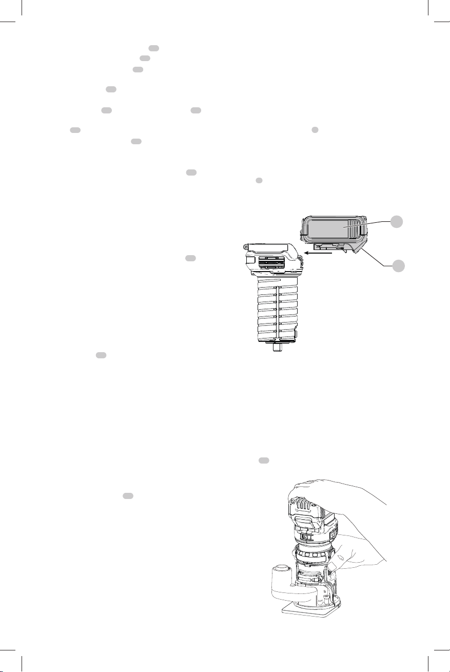
Installing and Removing the Battery Pack
(Fig. N)
CAUTION: Before inserting the battery, check
to see that the switch is in the OFF position. An
accidental start-up can causeinjury.
NOTE: For best results, make sure your battery pack is
fullycharged.
To install the battery pack
1
into the tool handle, align the
battery pack with the rails inside the tool’s handle and slide
it into the handle until the battery pack is firmly seated in
the tool and ensure that it does notdisengage.
To remove the battery pack from the tool, press the release
button
2
and firmly pull the battery pack out of the tool
handle. Insert it into the charger as described in the charger
section of thismanual.
Fig. N
1
2
Proper Hand Position (Fig. A, O, P)
WARNING: To reduce the risk of serious personal injury,
ALWAYS use proper hand position as shown.
WARNING: To reduce the risk of serious personal
injury, ALWAYS hold securely in anticipation of a
suddenreaction.
When using the fixed base, one hand should be on top
of the battery and the other hand around the fixed base
(Fig.O). When using the plunge base, grasp the side
handles
18
(Fig. A) firmly as shown in Fig.P.
Fig. O
Loading ...
Loading ...
Loading ...