Operator’s Manual Self Propelled Mower
ASSEMBLY
IMPORTANT: This mower is shipped without gasoline or oil in the engine. Be certain to service engine with gasoline and oil as instructed in the Operation section of the Engine Manual before starting or operating your mower.
NOTE: Reference to right and left hand side of the Lawn Mower is observed from the operating position.
Unpacking
OPENING CARTON
- Cut each corner of the carton vertically from top to bottom.
- Remove all loose parts: Grass Catcher (if equipped); Engine Oil
- Remove loose packing material.
REMOVING MOWER FROM CARTON
- Lift mower from the rear to detach it from underlying carton material and roll mower out of carton.
- Check carton thoroughly for any other loose parts.
- Remove any packing material which may be between upper and lower handles.
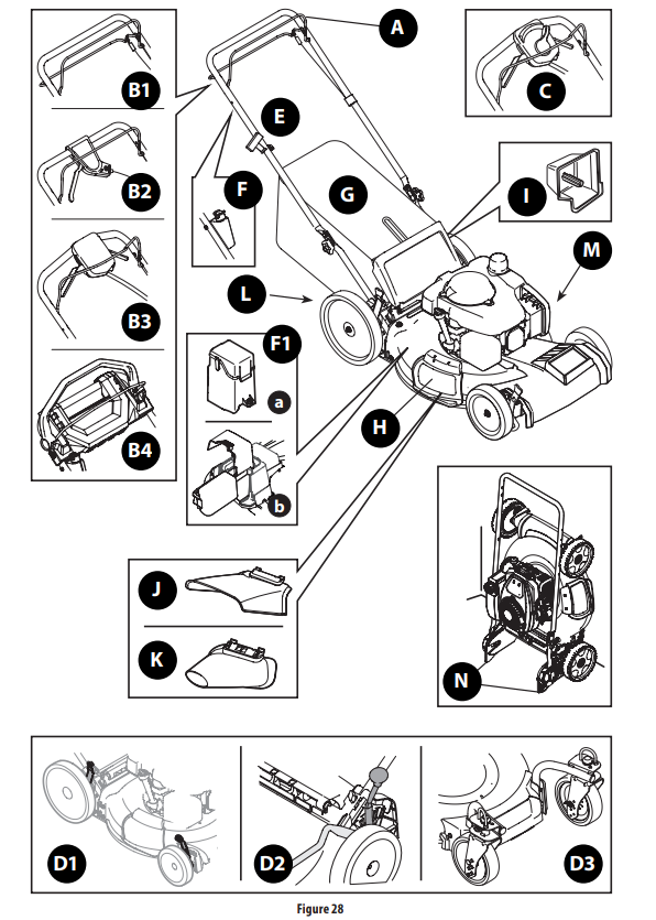
Mower Assembly: Preform the following procedures to assemble and set up the mower:
- Handle Assembly
- Pull-Out Handle.
- Folding Handle
- Vertical Storage Handle.
- Recoil Starter Rope Handle Assembly
- Attaching the Grass Catcher (if equipped)
- Attaching Side Discharge Chute or Side Discharge Blower (if equipped)
- Electric Start Set-Up (If Equipped)
NOTE: If necessary, refer to the procedures in the Adjustments Section after assembling the mower.
Handle Assembly
PULL-OUT HANDLE
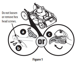
- Remove knobs or wing nuts (a) and carriage bolts (b) from the handle or if equipped with the EZ-lock handle (c), proceed to STEP 2 . NOTE: The EZ-Fold handle release levers are shipped in the unlocked position.
- Remove T-bolts (d) from the handle brackets
- While stabilizing mower so it doesn’t move, pivot upper handle (e) up
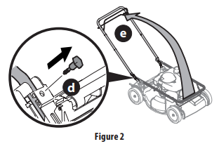
- Do not crimp blade or drive control cables while lifting the handle up.

- Reattach knobs or wing nuts (a) and carriage bolts (b) removed in STEP 2 into lower holes of the handle or lock the EZ-fold handle release levers (c)
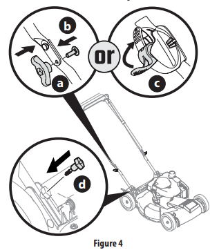 IMPORTANT: When locking the EZ-fold
 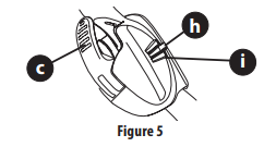 handle release lever (c) ensure the position indicator (h) aligns with one of three handle positions (i)
- Insert the T-bolts (d) removed in STEP 4 through the handle brackets and lower handle (Figure 4) and tighten securely to secure the handle in place.
FOLDING HANDLE
- Remove knobs or wing nuts (a) and carriage bolts (b) from the handle or if equipped with the EZ-lock handle (c), proceed to STEP 2 (Figure 6). NOTE: The EZ-Fold handle release levers are shipped in the unlocked position.

- Remove the T-bolts (d) from the handle brackets (Figure 6).
- While stabilizing mower so it doesn’t move, gently lift and pivot the upper handle into the operating position (Figure 7). Make certain the lower handle is seated securely into the handle brackets. Do not crimp blade or drive control cables while lifting the handle up

- Reattach knobs or wing nuts (a) and carriage bolts (b) removed in STEP 2 into lower holes of the handle or lock the EZ-fold handle release levers (c) (Figure 8).
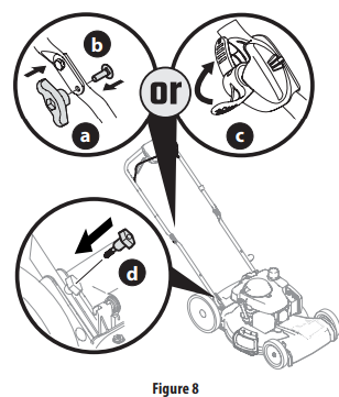 IMPORTANT: When locking the EZ-fold handle release lever (c) ensure the position indicator (e) aligns with one of three handle positions (f) (Figure 9).
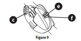
- Using the T-bolts (d) removed in STEP 2, secure the lower handle to the handle brackets (Figure 8) and tighten securely to secure the handle in place.
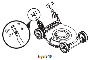
VERTICAL STORAGE HANDLE
- Remove the four carriage bolts and nuts from the lower handles (Figure 10).
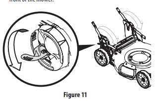
- Unlock the two handle release levers. See inset, Figure 11.
- Ensure the lower handles are folded forward towards the front of the mower.
- Using the four carriage bolts and nuts removed in STEP 2, secure the upper handle to the lower handle. Tighten hardware securely to secure the handle in place (Figure 12)

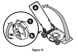
- While stabilizing mower so it doesn’t move, lift the upper handle up (a) (Figure 13). Do not crimp blade or drive control cables while lifting the handle up.
- When lifting the upper handle ensure the position indicator (b) aligns with one of three handle positions (c). See inset, Figure 13.
- Lock the two handle release levers. See inset, Figure 13.
- Ensure all hardware is securely tightened.
Recoil Starter Rope Handle Assembly
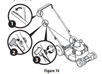
NOTE: The rope guide is attached to the right side of the upper handle. Loosen the knob securing the rope guide (Figure 14). NOTE: Vertical Storage Mowers Only: The recoil starter rope is equipped with a rope stop clamp to prevent the starter rope being pulled into the engine. Do not remove the rope stop clamp.
- Hold blade control against upper handle.
- Slowly pull recoil starter rope handle from engine and slip starter rope into the rope guide.
- Tighten rope guide knob.
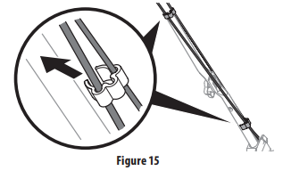
NOTE: On select units, use the two cable clips provided to secure blade control and drive cables to lower handle (Figure 15).
IMPORTANT: To reduce wear and allow for proper operation, make sure to leave some slack in the upper portion of the cables.
Attaching the Grass Catcher (If Equipped)
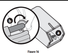
1. Perform the following to assemble the grass catcher (Figure 16).
NOTE: Before assembling the grass catcher, ensure the grass bag is turned right side out, with the warning label showing on the outside.
- Place bag over frame so that its black plastic side is at the bottom.
- Slip plastic channels (a) of grass bag over the frame (b).
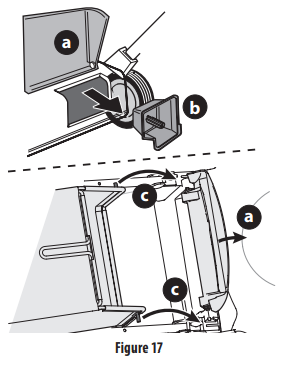
2. Follow steps below to attach grass catcher (Figure 17):
- Lift rear discharge door (a).
- Remove the rear mulch plug (b) (if equipped).
- Place grass catcher into the slots in the handle brackets (c). Lower the discharge door so that it rests on the grass catcher.
NOTE: To remove grass catcher, lift rear discharge door on the mower. Lift grass catcher up and off the slots in the handle brackets. Reinstall the rear mulch plug (if equipped). Release rear discharge door to allow it to close rear opening of mower.
Attaching Side Discharge Chute or Side Discharge Blower (If Equipped)
The mower is shipped as a mulcher. To convert to side discharge or side discharge blower, ensure the grass catcher is removed, the rear mulch plug is installed (if equipped) and the rear discharge door is closed.
- Lift the mulch plug (Figure 18).
- Slide the two hooks of the side discharge chute (a) or side discharge blower (b) under the mulch plug hinge pin. Lower the mulch plug.
IMPORTANT: Do not remove side mulch plug at any time.

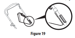
NOTE: Some side discharge chutes include a clip to secure the discharge chute to the handle. If equipped, the side discharge chute can be secured to the handle when not in use (Figure 19).
Electric Start Set-Up (If Equipped)
NOTE: Mowers equipped with electric start will use either a lead acid battery in an enclosed battery box (see Electric Starter Battery Box) or a removable lithium ion battery pack (See Installing/Removing Battery Pack).
ELECTRIC STARTER BATTERY BOX (IF EQUIPPED)
NOTE: Remove cable tie (a) from around battery box. Cable tie is used for shipping only (Figure 20).

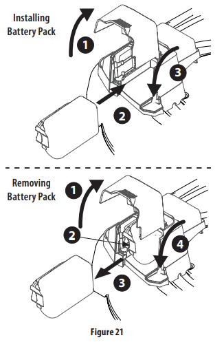
INSTALLING/REMOVING BATTERY PACK (IF EQUIPPED)
NOTE: To ensure maximum performance and life of lithium-ion battery packs, charge the battery fully before first use.
WARNING: Read all safety warnings, instructions, and cautionary markings for the battery pack, charger and product. Failure to follow the warnings and instructions may result in electric shock, fire and/or serious injury.
IMPORTANT: Refer to instructional manual supplied with battery charger for charging, maintenance and battery disposal instructions.
Installing The Battery Pack (Figure 21):
- Lift the battery box cover.
- Insert the battery pack into the battery box. An audible “click” will be heard when the battery is properly connected.
- Close the battery box cover.
Removing The Battery Pack (Figure 21):
- Lift the battery box cover.
- Press the battery pack release button.
- Pull the battery pack from the battery box.
- Close the battery box cover.
ADJUSTMENTS
Cutting Height Adjustments
This mower is equipped with one of three types of cutting height adjustment. Refer to Single Lever, Dual Lever or Rear Wheel/ Caster Wheels in this section.
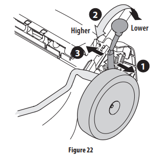
SINGLE LEVER : The single lever cutting height adjustment is located above the rear left wheel (Figure 22).
- Carefully pull the height adjustment lever outward towards wheel (mower will tend to fall when lever is moved outward).
- Move lever to desired position for a change in cutting height.
- Release lever towards deck
DUAL LEVER
Front Wheel Drive Mowers - The dual lever cutting height adjustment levers are located above the front and rear right wheels.
Rear Wheel Drive Mowers - The dual lever cutting height adjustment levers are located above the front and rear left wheels.
NOTE: Front wheel drive mower shown in Figure 23.
NOTE: On select mowers - The front and rear height adjustment levers move in the opposite direction to adjust height.
- Carefully pull the height adjustment lever outward towards wheel (mower will tend to fall when lever is moved outward).
- Move lever to desired position for a change in cutting height.
- Release lever towards deck.
IMPORTANT: All wheels must be placed in the same position. For rough or uneven lawns, move each height adjustment lever to a higher position. This will prevent you from cutting the grass too close to the ground.

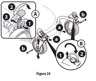
REAR WHEEL/CASTER WHEELS - NOTE: The rear wheel cutting height adjustment lever is located above the rear left wheel (Inset A, Figure 24).
1. Pull lever out and away from mower.
2. Move lever forward or back for desired cutting height.
3. Release lever towards mower deck. NOTE: The caster wheels cutting height are determined by selecting one of six positions on each caster assembly (Figure 24).
4. Remove wing nut (a) from axle bolt (b). Slide axle bolt from the assembly and select a cutting height.
5. Reinsert axle bolt in the square hole desired through wheel assembly and secure with wing nut removed in STEP 1. IMPORTANT: All wheels must be placed in the same relative position. For rough or uneven lawns, move the height adjustment lever to a higher position. This will stop scalping of grass.
6. The casters can be locked in a straight ahead position or positioned to swivel freely (Inset B, Figure 24).
- Lift lock pins.
- Place in larger holes to lock wheels. Place pins in smaller holes to allow casters to rotate freely for turning.
Handle Pitch (If Equipped)
For convenience of operation, you may adjust the pitch of the handle. Perform one of the following.
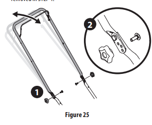
PULL-OUT AND FOLDING HANDLES
- Remove wing nuts and carriage bolts from handle (Figure 25).
- Position the handle in one of the three positions that is most comfortable. See Figure 25 inset.
- Secure into position with wing nuts and carriage bolts removed in STEP 1.
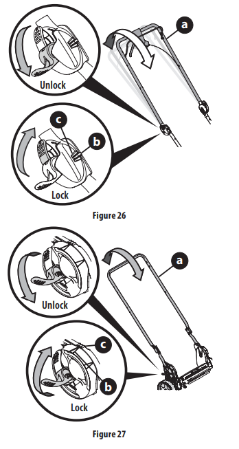
EZ-FOLD OR VERTICAL STORAGE HANDLES - NOTE: For EZ-Fold handles see Figure 26 or for vertical storage handles see Figure 27.
- Unlock the two handle release levers. See inset.
- Move the upper handle (a) to align the position indicator (b) with the most comfortable of the three handle positions (c).
- Lock the two handle release levers. See inset.
OPERATION
Features
A. BLADE CONTROL
- The blade control is attached to the upper handle of the mower. Depress and squeeze it against the upper handle to operate the mower. Release the blade control to stop blade and engine.
- WARNING This blade control is a safety device. Never attempt to bypass its operation.
B. DRIVE CONTROL There are four drive control configurations.
- Bail Drive Control (If Equipped) -The bail drive control is located on the underside of the upper handle and is used to engage the drive. Squeeze it against the upper handle to engage the drive; release it to stop mower.
- Single Lever Drive Control (If Equipped) - The single lever drive control is located on top of the upper handle and is used to engage the drive. Squeeze it against the upper handle to engage the drive; release it to slow down or stop mower.
- Dual Lever Drive Controls (If Equipped) - The dual lever drive controls are located on top of the upper handle and are used to engage the drive. Squeeze the right, left, or both right and left controls against the upper handle to engage the drive; release it/them to slow down or stop mower.
- Premium Drive Control (If Equipped) -The premium drive control is located on the upper handle and is used to engage the drive. Pushing the control forward will engage the drive. The farther the control is pushed forward, the faster the mower will propel. Once pressure is released from the control it will return to the neutral position and the drive will be disengaged.
C. SPEED CONTROL (IF EQUIPPED)
- The speed control is located on the variable speed control housing on the upper handle. This control is used to select the forward speed of the mower.
- IMPORTANT: Move the speed control only when the engine is running. Changing the speed control setting with the engine OFF can damage the mower.
D. CUTTING HEIGHT ADJUSTMENT LEVER: There are three cutting height adjustment configurations.
- Dual Lever - The dual lever cutting height adjustment levers are located above the front and rear right wheels. To adjust the cutting height, refer to Cutting Height Adjustment
- Single Lever - The cutting height adjustment lever is located above the rear left wheel. To adjust the cutting height, refer to Cutting Height Adjustment .
- Rear Wheel/ Caster Wheels - The rear wheel cutting height adjustment lever is located above the rear left wheel. The caster wheels adjust by moving the wheel bolts to the desired position. To adjust the cutting height, refer to Cutting Height Adjustment
E. RECOIL STARTER: The recoil starter is attached to the right upper handle. Stand behind the mower and pull the recoil starter rope to start the mower.
F. ELECTRIC STARTER PUSH KEY (IF EQUIPPED)
- The electric starter push key is located on the right side of the upper handle. It is both a removable key and push button and is only provided on electric start models.
- NOTE: Remove the key when the mower is unattended or in storage to prevent unauthorized operation. Keep key in a safe place out of the reach of children.
- Mowers equipped with electric starters are also equipped with a battery in an enclosed battery box (a) or a removable battery pack (b).
G. GRASS CATCHER (IF EQUIPPED): The grass catcher, located at the rear of the mower, is used to collect the grass clippings for disposal. Once the bag is full, remove it up through the handles and empty it before any further mowing.
H. MULCH PLUG (IF EQUIPPED): The mulch plug is located on the right side of the mower and is used for mulching purposes (recirculating the clippings back to the lawn).
I. REAR MULCH PLUG (IF EQUIPPED): On select mowers, the mulch plug is a separate component. If equipped, this mulch plug must be installed into the rear bagging discharge area when using the mower as a mulcher (recirculating the clippings back to the lawn) or side discharge.
J. SIDE DISCHARGE CHUTE (IF EQUIPPED):
- The side discharge chute is used to discharge grass clippings to the side of the mower instead of collecting the clippings in the grass catcher or using the mower as a mulcher.
- WARNING: Keep hands and feet away from the chute area on cutting deck. Refer to warning label on the unit.
K. SIDE DISCHARGE BLOWER (IF EQUIPPED): The side discharge blower is used to blow leaves, grass clippings and debris to the side.
L. TRAIL SHIELD: The trail shield is attached to the rear of the mower and is there to protect the operator from flying debris. Do not use the mower unless the shield is fully functional and in place.
M. DECK WASH (IF EQUIPPED): Your mower’s deck may be equipped with a fast attach deck wash nozzle on its surface as part of its deck wash system. Use the deck wash to rinse grass clippings from the deck’s underside.
N. VERTICAL STORAGE (IF EQUIPPED)
- This feature allows the handle to be folded forward and the mower tipped back and stored vertically. WARNING: Standing a mower with out the vertical storage feature in the upright position may cause damage to the engine or cause a fuel or oil leak. Only mowers with the vertical storage feature include an engine that can be stored in the upright position.
Gasoline And Oil Fill-up
IMPORTANT: Refer to the separate Engine Operator’s Manual for additional engine information. This mower is shipped without gasoline (fuel) or oil in the engine. Be certain to service engine with gasoline and oil as instructed before starting or operating your lawn mower.
- Add provided oil before starting mower for the first time as instructed in the separate Engine Operator’s Manual.
- Service the engine with gasoline as instructed in the separate Engine Operator’s Manual.
WARNING: Use extreme care when handling gasoline. Gasoline is extremely flammable and the vapors are explosive. Never fuel the machine indoors or while the engine is hot or running. Extinguish cigarettes, cigars, pipes and other sources of ignition
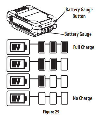
Checking Battery Pack Charge (if Equipped)
WARNING Read all safety warnings, instructions, and cautionary markings for the battery pack, charger and product. Failure to follow the warnings and instructions may result in electric shock, fire and/or serious injury.
IMPORTANT: Refer to instructional manual supplied with battery charger for charging, maintenance and battery disposal instructions.
1. Press the battery gauge button on front of the battery pack to check charge level
- Charged Battery - One to three lights of the battery gauge will light to show charge level.
- Discharged Battery - If no lights show, charge battery pack. Refer to manual supplied with battery charger for charging instructions.
To Start Engine
- WARNING: Be sure no one other than the operator is standing near the lawn mower while starting engine or operating mower. Never run engine indoors or in enclosed, poorly ventilated areas. Engine exhaust contains carbon monoxide, an odorless and deadly gas. Keep hands, feet, hair and loose clothing away from any moving parts on engine and lawn mower.
- Refer to the Engine Operator’s Manual for instructions on starting and stopping the engine.
To Stop Engine
- Release blade control to stop the engine and blade.
- NOTE: If equipped with an electric starter push key, remove the key when the mower is unattended to prevent unauthorized operation.
- WARNING: Wait for the blade to stop completely before performing any work on the mower or to remove the grass catcher. Check blade stopping time is within 3 seconds. If blade does not stop within 3 seconds contact your Service Center.
Using Your Lawn Mower
WARNING: The operation of any lawn mower can result in foreign objects being thrown into the eyes, which can damage your eyes severely. Always wear safety glasses while operating the mower, or while performing any adjustments or repairs.
Be sure lawn is clear of stones, sticks, wire, or other objects which could damage lawn mower or engine. Such objects could be thrown by the blade in any direction and cause serious personal injury to the operator and helpers
BAIL DRIVE CONTROL
- Once the engine is running, squeeze the bail drive control against the upper handle to propel mower.
- Release the bail drive control to stop mower from propelling.
SINGLE LEVER DRIVE CONTROL
- Once the engine is running, squeeze the single lever drive control against the upper handle to propel mower.
- Release the single lever drive control to slow down or stop mower from propelling.
DUAL LEVER DRIVE CONTROLS
1. Once the engine is running and while continuing to hold the blade control down, squeeze either (or both) drive controls against the upper handle to propel mower
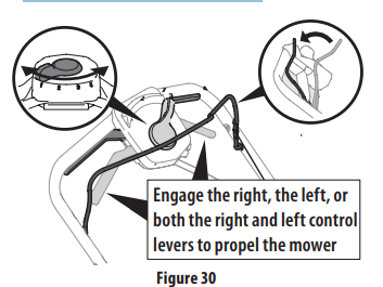
2. Release the dual lever drive controls to slow down or stop mower.
3. Speed Control (if equipped) - To change speed, move speed control to the desired speed.
NOTE: When selecting a drive speed, use the first speed until you are comfortable and familiar with the operation of the mower.
IMPORTANT: If you are shifting speeds while the mower is stationary it may be difficult to shift into first speed under certain conditions. This is easily remedied by briefly engaging the drive lever.
NOTE: Your mower is equipped with an advanced internal drive system for ease of use and smooth shifting. When turning or pulling the unit rearward, you may notice higher than normal resistance in the rear wheels under certain conditions. This is perfectly normal and can be remedied by allowing the unit to roll forward slightly without the drive lever(s) engaged before pulling backwards.
PREMIUM DRIVE CONTROL
- Once the engine is running and while continuing to hold the blade and drive controls together, push the drive control forward to propel mower. The farther the control is pushed forward, the faster the mower will propel (Figure 31).

- Once pressure is released from the control it will return to the neutral position and the drive will be disengaged and mower will stop.
NOTE: For ease of use, while gripping the controls, simply lock your wrist and elbows and walk - the unit will automatically adjust to your speed.
Using Side Discharge Chute (If Equipped)
- To use the mower without mulching or collecting grass, remove the grass catcher and ensure the rear mulch plug (if equipped) is installed. Allow the rear discharge door to close the rear opening of mower. Refer to Attaching The Side Discharge Chute or Side Discharge Blower in on page 11.
Using Mower as a Mulcher (If Equipped)
- For mulching grass, remove the grass catcher or side discharge chute from the mower. When you remove the grass catcher from the mower, ensure the rear mulch plug (if equipped) is installed and allow the rear discharge door to close the rear opening of mower. When you remove the side discharge chute, the mulching plug will close. For effective mulching, do not cut wet grass. If the grass has been allowed to grow in excess of four inches, mulching is not recommended. Use the grass catcher to collect clippings instead.
Using Mower with Grass Catcher (If Equipped)
You can use the grass catcher to collect clippings while you are operating the mower.
- Attach grass catcher, refer to Attaching the Grass Catcher. Grass clippings will automatically collect in bag. Operate mower until grass bag is full.
- Stop engine by releasing the blade control. Make sure that the engine has come to a complete stop.
- Lift rear discharge door and pull grass bag up and away from the mower to remove the bag. Dispose of the grass clippings and reinstall the bag when complete.
WARNING: If you strike a foreign object, stop the engine. Disconnect the spark plug wire, thoroughly inspect mower for any damage, and repair damage before restarting and operating. Extensive vibration of mower during operation is an indication of damage. The mower should be promptly inspected and repaired.
Vertical Storage Mower (If Equipped) - WARNING
- Standing a mower without the vertical storage feature in the upright position may cause damage to the engine or cause a fuel or oil leak.
- Only mowers with the vertical storage feature include an engine that can be stored in the upright position.
- Do not store the mower outside or in damp area. Store mower in a dry, clean area.
STORING THE MOWER
WARNING: Wait for engine to cool before wiping or storing
IMPORTANT: Before storing the mower in the vertica l position ensure the fuel level is at or below the recommended fill level. Refer to the Engine Operator’s Manual.
- Using compressed air or dry rag clean the outside of the mower and remove any debris from around the engine.
- If equipped, remove the starting key.
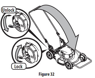
- Unlock the two handle release levers. See inset Figure 32.
- Fold the handle forward to the storage position (Figure 32). Do not crimp blade control cable or the drive control cable (if equipped) while lowering the handle.
- Lock the two handle release levers (inset, Figure 32).
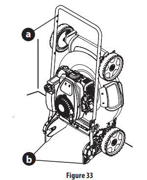
- Lifting from the handle (a), tilt the mower up onto the rear wheels and back of the handle bracket (b) (Figure 33).
- Position the mower so that the blade is facing a wall.
REMOVING THE MOWER FROM STORAGE
WARNING:
- When moving the mower or unfolding the handle do not put hands or feet near or under the cutting deck. Otherwise serious injury may occur.
- To prevent accidentally starting the mower engine when unfolding the handle, do not hold the blade control against the upper handle. Otherwise serious injury may occur.
8. Holding the mower by the upper handle, gently set the mower down on all four wheels.
9. To unfold the handle, unlock the two handle release levers (inset, Figure 32) and perform STEPS 5-8 in ASSEMBLY, Vertical Storage Handle
SERVICE AND MAINTENANCE
WARNING: Before performing any type of maintenance/service, disengage all controls and stop the engine. Wait until all moving parts have come to a complete stop. Allow the engine to cool. Disconnect spark plug wire and ground it against the engine to prevent unintended starting.
General Recommendations
- Always observe safety rules on the mower and in the manual(s) when performing any maintenance.
- The warranty on this mower does not cover items that have been subjected to operator abuse or negligence. To receive full value from warranty, operator must maintain the mower as instructed here.
- Changing of engine-governed speed will void engine warranty.
- Check that all hardware is in place & secure and tight before each use and before off season storage.
Lubrication
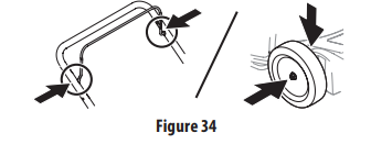
BLADE CONTROL: Lubricate pivot points on the blade control at least once a season and before storage with light oil. This control must operate freely in both directions (Figure 34).
WHEELS: Lubricate all wheel hubs/axles at least once a season and before storage with light oil (Figure 34).
Engine Maintenance
Annually check the engine mounting bolts torque: Min. 29.2 ft-lbs (39.6 N-m), Max. 41.7 ft-lbs (56.3 N-m).
Refer to the Engine Operator’s Manual packed with your mower for a detailed description of all engine-related service specifications and storage.
If engine fails to start, runs erratic, overheats, skips (hesitates) or idles poorly refer to the Engine Operator’s Manual.
IMPORTANT: Check engine oil level before each use. Refer to Engine Operator’s Manual.
CLEAN ENGINE
- Before every use, clean grass, chaff or accumulated debris from engine. Keep linkage, spring, and controls clean. Keep area around and behind muffler free of any combustible debris.
- Keeping engine clean allows air movement around engine.
- Engine parts should be kept clean to reduce the risk of overheating and ignition of accumulated debris.
CAUTION: Do not use water to clean engine parts. Water could contaminate fuel system. Use a brush or dry cloth.
Mower Maintenance
DECK WASH (IF EQUIPPED): Your mower’s deck may be equipped with a deck wash system. Use the deck wash to rinse grass clippings from the deck’s underside and prevent the buildup of corrosive chemicals. Complete the following steps AFTER EACH MOWING:
- Push the mower to a level, clear location on your lawn. Ensure your garden hose can reach your mower. CAUTION Make certain the mower’s discharge chute is directed AWAY from your house, garage, parked cars, etc.
- Remove the fast attach deck wash nozzle from the mower deck and thread it onto the end of your garden hose.
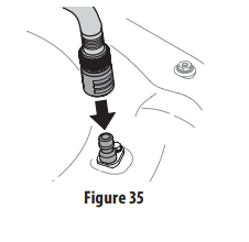
- Attach garden hose with the deck wash nozzle to the water port on your deck’s surface (Figure 35).
- Turn the water ON.
- Start the engine as described in the Engine Operator’s Manual.
- Run the engine for a minimum of two minutes, allowing the underside of the cutting deck to thoroughly rinse.
- Release blade control to stop the engine and blade.
- Turn the water OFF and detach the deck wash nozzle from the water port on your deck’s surface.
- After cleaning your deck, restart the mower. Keep the engine and blade running for a minimum of two minutes, allowing the underside of the cutting deck to thoroughly dry
DECK CLEANING: At least once a season and before storage, clean the underside of the mower deck to prevent build-up of grass clippings or other debris.
- Allow the engine to run until it is out of fuel. Do not attempt to pour fuel from the engine. Disconnect spark plug wire. Refer to Engine Operator’s Manual.
- Turn mower on its side keeping the muffler side down and making sure that the air filter and the carburetor are facing up. Hold mower firmly.
- Scrape and clean the underside of the deck with a suitable tool. Do not spray with water. IMPORTANT: Do not use a pressure washer or garden hose to clean your mower. These may cause damage to bearings, or the engine. The use of water will result in shortened life and reduce serviceability.
- Put the mower back on its wheels on the ground.
Blade Care
WARNING: Wait for the blade to stop completely before performing any work on the mower or to remove the grass catcher. Check blade stopping time is within 3 seconds. If blade does not stop within 3 seconds contact your Service Center.
WARNING: When removing the cutting blade for sharpening or replacement, protect your hands with a pair of heavy gloves or use a heavy rag to hold the blade.
Annually check the mower blade mounting bolt torque: Min. 37.5 ft-lbs (50.8 N-m), Max. 50.0 ft-lbs (67.8 N-m).
Periodically inspect the blade and blade adapter for bends or cracks, especially if you strike a foreign object or experience excessive vibration. Replace when necessary. Follow the steps below for blade service:
1. Allow the engine to run until it is out of fuel. Do not attempt to pour fuel from the engine.
2. Disconnect spark plug wire. Refer to Engine Operator’s Manual.
3. Turn mower on its side keeping the muffler side down and making sure that the air filter and the carburetor are facing up.
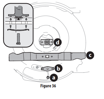
4. Remove bolt (a) and blade bell support (b) which hold the blade and the blade adapter to the engine crankshaft (Figure 36).
5. Remove blade (c) and blade adapter (d) from the crankshaft (Figure 36).
6. Remove blade from the blade adapter for testing balance.
- Balance the blade on a round shaft screwdriver to check.
- Remove metal from the heavy side until it balances evenly. NOTE: When sharpening the blade, follow the original angle of grind. Grind each cutting edge equally to keep the blade balanced. WARNING An unbalanced blade will cause excessive vibration when rotating at high speeds. It may cause damage to engine and blade could break causing personal injury.
7. Lubricate the engine crankshaft and the inner surface of the blade adapter with light oil (Figure 36 inset).
- Slide the blade adapter (d) onto the engine crankshaft.
- Place the blade on the adapter such that the side of the blade marked “Grass Side” (or with part number) faces the ground when the mower is in the operating position.
- Make sure that the blade is aligned and seated on the blade adapter flanges.
8. Place blade bell support (b) on the blade (c). Align notches on the blade bell support with small holes in blade.
9. Replace hex bolt (a) and tighten hex bolt to torque: Min. 37.5 ft-lbs (50.8 N-m), Max. 50.0 ft-lbs (67.8 N-m).
NOTE: To ensure safe operation of your mower, periodically check the blade bolt for correct torque.
Belt Care
- A damaged or worn belt may prevent the mower from selfpropelling. Periodically inspect the belt and pulley system for damage or wear. If necessary contact an authorized Service Center to have belt replaced.
- NOTE: Several components must be removed in order to change the mower’s drive belt. See an authorized Service Center to have belt replaced.
Drive Control Adjustment
SINGLE LEVER AND DUAL LEVER DRIVE CONTROLS (IF EQUIPPED)
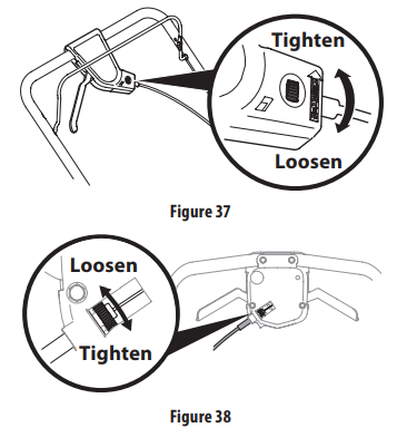
- If equipped, there is an adjustment wheel located in the drive control handle housing that is used to tighten or loosen the drive belt. You will need to adjust the drive control if the mower does not propel itself with the drive control engaged or if the mower’s wheels hesitate with the drive control engaged. If either of these conditions occur, rotate adjustment wheel clockwise to tighten cable or counterclockwise to loosen the cable. See Figure 37 for location on Single Lever Drive Control and Figure 38 for Dual Lever Drive Control.
PREMIUM DRIVE (IF EQUIPPED): The drive system consists of pulleys, a belt , and a cable linking the transmission to the drive handle. As these components wear, adjustment may be needed. To adjust the drive linkage perform the following:
1. Rotate the drive cable fitting located on the left upper handle upward (Figure 39).
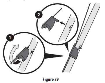
2. Pull the fitting away from the handle.
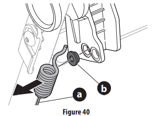
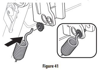
3. Unhook the cable (a) and remove the metal bushing (b) from the plastic drive handle (Figure 40).
4. Replace bushing in the lower hole and reattach the cable through the bushing and lower hole in the handle (Figure 41).
5. Reinsert the drive cable fitting into the upper handle and rotate it downward.
6. Start the mower and check the function of the drive handle.
Replacing Battery (If Equipped)
WARNING: Batteries contain sulfuric acid which may cause burns. Do not short circuit or damage batteries in any way. Do not put batteries in fire as these may burst or release toxic materials
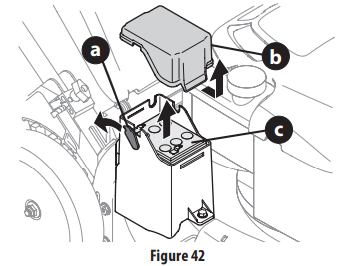
1. Removing the battery (Figure 42):
- Open the charging port cover (a) and remove the battery box cover (b).
- Disconnect the positive and negative leads from the battery (c).
- Lifting up, remove the battery from the battery box
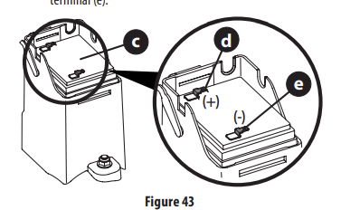
2. Installing the battery (Figure 43):
- Insert the battery (c) into the battery box.
- Connect the positive lead (red) to the positive (+) terminal (d).
- Connect the negative lead (black) to the negative (-) terminal (e).
3. Install the battery box cover and close the charging port cover.
Charging Battery (If Equipped)
WARNING: The battery contains corrosive fluid and toxic material; handle with care and keep away from children. Do not puncture, disassemble, damage or incinerate the battery. Explosive gases could be vented during charging or discharging. Use in a well ventilated area, away from sources of ignition.
Charge the battery at initial setup, at end of the season, after extended periods of non-use, and as needed.
The battery may need to be charged more often if stopping and starting the mower frequently during each cut throughout the season, such as when bagging.
NOTE: The specially designed plug on the charger lead will only fit into the charging port on the battery box.
NOTE: The battery must be stored with a full charge. Extended storage of a discharged battery will reduce life and capacity of the battery. For optimal battery life, charge the battery once per month while in storage.
IMPORTANT: Do not remove the battery from the battery box for any reason other than replacement
1. Open the charging port cover (a) and plug the charger lead (b) into the charging port (c) (Figure 44).
2. Plug the battery charger (d) into a standard 120V household outlet.
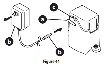
3. Charge battery for 8 to 10 hours before initial use. Do not charge longer than 12 hours. IMPORTANT: Always plug charger lead into charging port first, and then plug battery charger into 120V standard household outlet. Follow this order of steps every time you charge the battery.
4. After charging, disconnect the charger from outlet first, then disconnect the charger lead from the charging port.
5. Close the charging port cover
Charging the Battery Pack (If Equipped)
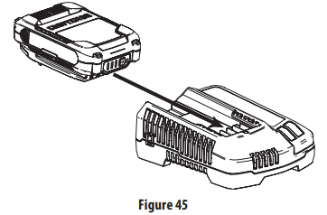
IMPORTANT: Refer to instructional manual supplied with battery charger for charging, maintenance and battery disposal instructions (Figure 45).
WARNING The battery contains corrosive fluid and toxic material; handle with care and keep away from children. Do not puncture, disassemble, mutilate or incinerate the battery. Explosive gases could be vented during charging or discharging. Use in a well ventilated area, away from sources of ignition.
WARNING Read all safety warnings, instructions, and cautionary markings for the battery pack, charger and product. Failure to follow the warnings and instructions may result in electric shock, fire and/or serious injury.
Battery Disposal
IMPORTANT: This procedure refers to mowers equipped with a battery in an enclosed battery box. For mowers equipped with a removable battery pack, refer to instructional manual supplied with battery charger for disposal instructions.
DISPOSING OF DAMAGED OR WORN-OUT BATTERIES
- WARNING: The following toxic and corrosive material is used in this battery: SULFURIC ACID, a toxic material.
- WARNING: To prevent contamination of the environment, contact your local waste disposal agency for specific instructions before disposing of damaged or worn-out lithium-ion batteries. Take batteries to a local recycling and/or disposal center, certified for lithium-ion battery disposal.
- WARNING Do not use broken or cracked batteries, even if there is no leakage. Replace damaged or worn-out batteries with new batteries. DO NOT ATTEMPT TO REPAIR BATTERIES! Repair attempts may result in severe personal injury, due to explosion or electrical shock.
To avoid personal injury and damage to the environment:
- Do not attempt to remove or destroy any of the battery components. Do not open or mutilate the battery. If a leak develops, released electrolytes are corrosive and toxic. Do not get the solution in your eyes or on your skin, and do not swallow it.
- Do not dispose of the battery in the regular household trash.
- Do not dispose of the battery in a fire. The cell may explode.
- Do not dispose of the battery where it will become part of any waste landfill or municipal solid waste stream.
- Cover the battery terminals with heavy-duty adhesive tape.
- Dispose of the battery according to local, state and federal regulations.
- Dispose of the battery promptly
BATTERIES LABELED WITH THE CALL2RECYCLE BATTERY SEAL
- About Call2Recycle Battery Seals - Call2Recycle’s industry steward program helps battery and product manufacturers fulfill recycling requirements in the U.S. and Canada, including compliance with extensive state, provincial and federal regulations, such as the MercuryContaining and Rechargeable Battery Act (The Battery Act). Call2Recycle® Licensees/Industry Stewards, participating battery and product manufacturers and marketers, purchase the rights to imprint the Call2Recycle Battery Seals on their rechargeable batteries and products. When you see the Call2Recycle Battery Seal, you can feel confident knowing that your battery or product can be safely and responsibly recycled.
- About Call2Recycle - Since 1994, Call2Recycle has diverted more than 75 million pounds of rechargeable batteries from local landfills and established a network of 30,000 recycling drop-off locations. More than 200 battery and/or product manufacturers, Call2Recycle Industry Stewards, have united to ensure that batteries are responsibly recycled when they reach their end of life and fund the program that is operated by Call2Recycle, Inc., a 501(c)4 nonprofit public service organization.