Loading ...
Installation instructions
For flush installation of a frameless hob
with cement set and sealing strips
J004133-R12
12/06/2018
J004133-R12
2
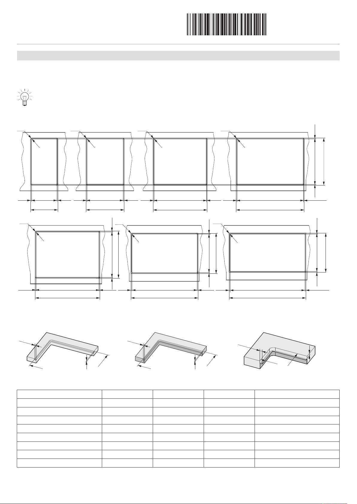
Cut-out with integral mounting surfaces or with mounting angles
Cut-out dimensions
It is recommended to use a work surface (cover) with a material thickness of at least 20mm. Ream out the cut-out as accurate and
rectangular as possible and ensure compliance with the stated measurement tolerances.
Access must be guaranteed to the hob from below over the entire cut-out area. For servicing, the entire hob base can
be taken out from below. It must be possible for touch protection covers to be unscrewed and removed from under-
neath.
Cut-outs up to the end of 2012 and for Quicklight hobs
Ri
Ra
Installation
dimension 40
Ri
Ra
Installation
dimension
30
R
i
Ra
Installation
dimension 60
Ri
Ra
Installation dimension 70
8.5
8.5
483 ±1
T
8.5 466
373261 536 6808.5
390 ±1
B
8.5 8.5
278 ±1
B
5.8
553 ±1
B
697 ±1
B
Installation dimension 80
Panorama
Installation dimension 90
Panorama
Ri
R
i
Ri
Ra Ra
Installation dimension 80
8.5
Ra
403
726
733
869
369
466
8.58.5
8.5 8.5 8.58.5
8.58.5
8.5
420 ±1
T
386 ±1
T
743 ±1
B
750 ±1
B
886 ±1
B
483 ±1
T
0
-1
0
-1
0
-1
0
-1
0
-1
0
-1
0
-1
0
-1
0
-1
0
-1
0
-1
0
-1
0
-1
0
-1
0
-1
0
-1
0
-1
Creating the hob mounting
The mounting surface can either be reamed out (Fig.1), or created by installing wood/stone supports (Fig.2) or steel angles (Fig.3).
8.5
8.5
8.5
0
-1
0
-1
0
-1
B
T
T
B
T
H
H
H
Fig. 3Fig. 2Fig. 1
B
Reamed out stone panel Execution with wood/stone supports,
bonded or screw mounted
Execution with steel angle,
bonded or screw mounted
Installation dimension H Ra Ri Art. no. angle set
30 8.5 0/+1 14 0–5 H62570
40 8.5 0/+1 14 0–5 H62571
60 8.5 0/+1 14 0–5 H62084
70 8.5 0/+1 14 0–5 H62567
80 8.5 0/+1 14 0–5 H62085
90 8.5 0/+1 14 0–5 H62981
80 Panorama 8.5 0/+1 5 0–5 H62679
90 Panorama 8.5 0/+1 5 0–5 H62568
Loading ...
Loading ...
Loading ...