Loading ...
Loading ...
Loading ...
72 Servicing Your Honda
Valve Clearance
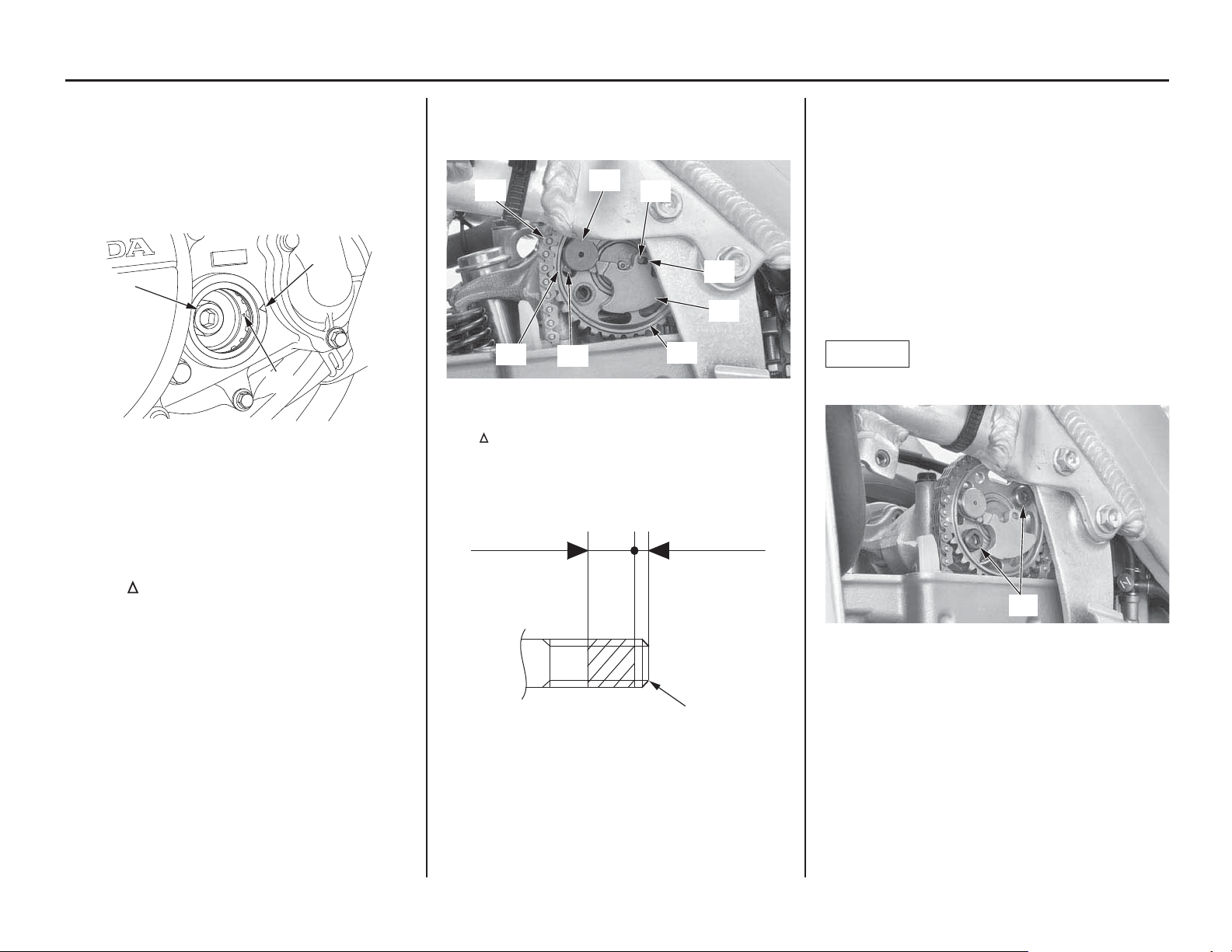
6. While holding the cam chain, rotate the
primary drive gear bolt (12) (crankshaft)
clockwise and align the punch mark (13) with
the index mark (14).
Make sure the piston is at TDC (Top Dead
Center) on the compression stroke.
(12)
(14)
(13)
(12) primary drive gear bolt
(13) punch mark
(14) index mark
7. Install the cam chain (15) over the sprocket
without rotating the sprocket.
Place the cam sprocket (16) and align the
timing mark (17) on the cam sprocket with
the “
” mark (18) on the camshaft holder
assembly.
When installing the cam sprocket, position
the decompressor weight pin (19) toward the
front side.
8. Set the decompressor weight (20) by aligning
its hole (21) with out side weight pin (22) as
shown.
(15)
(19)
(22)
(21)
(20)
(16)
(18)
(17)
(15) cam chain (19) decompressor weight pin
(16) cam sprocket (20) decompressor weight
(17) timing mark (21) hole
(18) “
” mark (22) out side weight pin
9. Clean and apply a locking agent to the cam
sprocket bolt (25) threads (coating width as
shown).
(23) 0.26 ± 0.04 in
(6.5 ± 1.0 mm)
(24) 0.04 – 0.08 in
(1.0 – 2.0 mm)
(25)
(23) coating width
(24) no coating width
(25) cam sprocket bolt
10. Temporarily install the cam sprocket bolt (25)
by aligning the bolt holes of the cam sprocket
and camshaft.
Rotate the primary drive gear bolt
(crankshaft) clockwise one turn and tighten
the sprocket bolt to the specified torque:
15 lbf·ft (20 N·m, 2.0 kgf·m)
Rotate the primary drive gear bolt
(crankshaft) clockwise one turn again and
tighten the other sprocket bolt to the specified
torque (see above).
NOTICE
Do not let the bolts fall into the crankcase.
(25)
(25) cam sprocket bolts
Loading ...
Loading ...
Loading ...