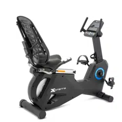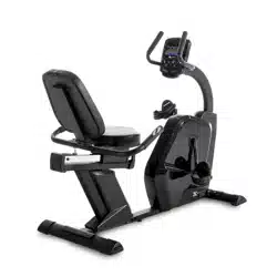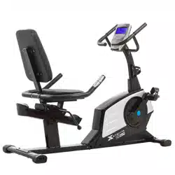
SB120 Recumbent Bike
OWNER’S MANUAL
PLEASE CAREFULLY READ THIS ENTIRE MANUAL BEFORE OPERATING YOUR NEW RECUMBENT BIKE.

Table Of Contents
1
2
3
4
7
17
18
20
21
WARRANTY COMPLIANCE
THIS RECUMBENT BIKE IS INTENDED FOR RESIDENTIAL USE ONLY AND IS
WARRANTED FOR THE APPLICATION. ANY OTHER APPLICATION VOIDS THIS
WARRANTY IN ITS ENTIRETY.
Product Registration
Important Safety Instructions
Important Operation Instructions
Exploded View and Parts Lists
SB120 Assembly Instructions
Final Considerations
Exploring Your New Bike
Troubleshooting
Manufacturer’s Limited Warranty

SB120 Recumbent Bike
1
Record Your Serial Number
Please record the Serial Number of this tness product
in the space provided below.
Serial Number
Register Your Purchase
The self-addressed product registration card must be completed in full and returned to
XTERRA Fitness. You can also go to www.xterratnessstore.com/warrantyreg.html
to register online.
Thank you for your purchase of this quality Recumbent Bike. Your new Recumbent Bike has
been manufactured by one of the leading tness manufacturers in the world and is backed by
one of the most comprehensive warranties available. XTERRA Fitness will do all we can to
make your ownership experience as pleasant as possible for many years to come.
If you have questions, or if parts are missing or damaged, or you require customer service,
call (870) 333-5500. Please have your model number and serial number handy when you call.
Please take a moment to record where you purchased your machine, as well as the date of
purchase for future reference. We appreciate your condence in XTERRA Fitness and we
will always remember that you are the reason that we are in business. Please complete and
mail your registration card today and enjoy your new Recumbent Bike.
Yours in Health,
XTERRA Fitness
Congratulations On Your New Recumbent Bike and Welcome to the XTERRA Fitness
Family!
Product Registration
SB120_201901011
Version 5.0
Purchase Location
Purchase Date

2
SB120 Recumbent Bike
WARNING - Read all instructions before using this appliance.
1. Use this equipment only for its intended use as described in this manual. Do not
attempt to ride this bike at high pedal speeds until you have ridden the bike for some
time and are comfortable riding at slower pedal speeds.
2. Serious injury or death may occur from over-training. Consult a medical doctor or
qualied tness instructor to determine an exercise program appropriate for your level
of tness.
3. Do not attempt to turn the pedal cranks by hand. Do not touch any driving mechanism
while it is in motion as possible injury could occur.
4. In a home setting, keep children away from the bike when it is not in use. Keep
children and pets away from the unit while it is in use.
5. Do not attempt to perform dip movements on handlebars.
6. Never drop or insert any object into any opening of the bike.
7. Only use the bike on a stable, level oor.
8. Follow instructions for safe use of the equipment including proper seat position,
handlebar position, and use of foot positioning system of pedals.
9. For safe operation, allow for at least 1 foot (30cm) of free space to either side of the
unit and 2 feet (60cm) of free space to the rear of the unit.
10. Weight Limit: 250 lbs.
Regularly examine the bike for damage and wear. Inoperable components should be
replaced immediately or the equipment should not be used until it is repaired.
Failure to follow all guidelines may compromise the effectiveness of the exercise
experience, expose yourself (and possibly others) to injury, and reduce the longevity
of the equipment.
SAVE THESE INSTRUCTIONS - THINK SAFETY!
Important Safety Instructions
WARNING: This product can expose you to chemicals including Toluene and Acrylamide which
are known to the State of California to cause cancer and birth defects or other reproductive harm.
For more information go to www.P65Warnings.ca.gov

SB120 Recumbent Bike
3
1. Obtain a complete physical examination from your medical doctor and enlist a health/
tness professional’s aid in developing an exercise program suitable for your current
health status.
2. When working out for the rst time, start out slowly for a minimum of ve minutes.
After your muscles are warmed up, gradually increase the pedaling speed and/or
resistance.
3. The speed and duration of your exercise program should always be subject to how
you feel. Never permit peer pressure to exceed your personal judgment while
exercising.
4. This exercise equipment is not intended for use by persons with reduced physical,
sensory or mental capabilities, or lack of experience and knowledge.
5. Overweight or severely de-conditioned individuals should be particularly cautious
when using the equipment for the rst time. Even though such individuals may not
have histories of serious physical problems, they may perceive the exercise to be far
less intense than it really is, resulting in the possibility of overexertion or injury.
6. Proper installation and regular maintenance are required to ensure user’s safety.
Maintenance is the sole responsibility of the owner.
Important Operation Instructions
WARNING - AS THE OWNER OF THIS EXERCISE EQUIPMENT, YOU SHOULD
INSIST THAT ALL USERS FOLLOW THE SAME GUIDELINES: YOU SHOULD MAKE
THIS MANUAL AVAILABLE TO ALL USERS.
4
SB120 Recumbent Bike
24
23
19
33
31
02
56
46
04
25
26
18
47
03
47
45
52
20
63
16
33
05
21
46
36
49
14
22
15
07
57
29
35
28
33
30
50
27
48
64
55
40
54
65
60
09
20
34
08
62
32
12
13
11
61
01
41
70
51
10
33
17
71
38
68
53
66
06
15
37
58
33
30
67
54
54
44
54
54
39
43
54
39
54
42
39
39
44
67
68
38
69
59
72
73
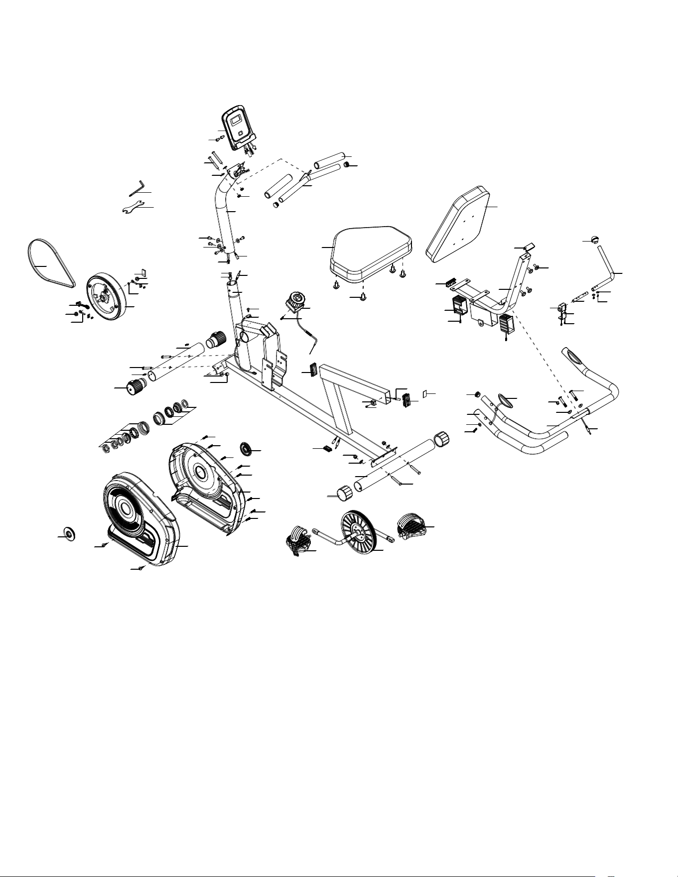
SB120 Exploded View Diagram

SB120 Recumbent Bike
5
SB120 Parts List
Part No. Serial No. Description Q’TY
01 SB120-RB1036-PART01 Main frame 1
02 SB120-RB1036-PART02 Front post 1
03 SB120-RB1036-PART03 Backrest support bracket 1
04 SB120-RB1036-PART04 Front handlebar 1
05 SB120-RB1036-PART05 Rear handlebar 1
06 SB120-RB1036-PART06 Front stabilizer φ50x1.2tx395L 1
07 SB120-RB1036-PART07 Rear stabilizer φ50x1.2tx490L 1
08 SB120-RB1036-PART08 Adjustable bar 16x2tx305L 1
09 SB120-RB1036-PART09 Connection axle φ12x95L 1
10 SB120-RB1036-PART10 Upper sensor wire 1
11 SB120-RB1036-PART11 Lower sensor wire 1
12 SB120-RB1036-PART12 Upper pulse sensor wire 1
13 SB120-RB1036-PART13 Pulse sensor wire 1
14 SB120-RB1036-PART14 Middle pulse sensor wire 1
15 SB120-RB1036-PART15 Carriage bolt M8x60L 4
16 SB120-RB1036-PART16 Allen screw M8x40L 2
17 SB120-RB1036-PART17 Allen screw M8x15L 4
18 SB120-RB1036-PART18 Allen bolt M8x35L 4
19 SB120-RB1036-PART19 Allen bolt M8x65L 2
20 SB120-RB1036-PART20 Allen bolt M6x20L 4
21 SB120-RB1036-PART21 Lower pulse sensor wire 1
22 SB120-RB1036-PART22 Crossed head self-tapping screw M4x10L 1
23 SB120-RB1036-PART23 Crossed head screw M5x10L 2
24 SB120-RB1036-PART24 Console 1
25 SB120-RB1036-PART25 Seat 1
26 SB120-RB1036-PART26 Back cushion 1
27 SB120-RB1036-PART27 Limited bracket JE099 1
28 SB120-RB1036-PART28 Pedal (L) JG-16B 1
29 SB120-RB1036-PART29 Pedal (R) JG-16B 1
30 SB120-RB1036-PART30 Domed nut M8x16t 4
31 SB120-RB1036-PART31 Nut M8x8t 2
32 SB120-RB1036-PART32 Allen screw M8x15L 4
33 SB120-RB1036-PART33 Curved washer φ8.5xφ20x1.5t 12
34 SB120-RB1036-PART34 Flat washer φ6.5xφ13x1.5t 2
35 SB120-RB1036-PART35 Crank w/ pulley 1

6
SB120 Recumbent Bike
SB120 Parts List
36 SB120-RB1036-PART36 Sticker 1
37 SB120-RB1036-PART37 Crossed head self-tapping screw
ST4.2x12L
2
38 SB120-RB1036-PART38 Flange nut M10x1Px6t 2
39 SB120-RB1036-PART39 Crossed head self-tapping screw st4.2x20L 4
40 SB120-RB1036-PART40 Flat washer φ4.3xφ12x1t 2
41 SB120-RB1036-PART41 Sensor bracket 1
42 SB120-RB1036-PART42 Chain cover L 1
43 SB120-RB1036-PART43 Chain cover R 1
44 SB120-RB1036-PART44 Cover for crank JE437 2
45 SB120-RB1036-PART45 End cap for sliding seat 2
46 SB120-RB1036-PART46 End cap for front handlebar 4
47 SB120-RB1036-PART47 End cap for seat post 2
48 SB120-RB1036-PART48 End cap 1
49 SB120-RB1036-PART49 End cap 1
50 SB120-RB1036-PART50 End cap 1
51 SB120-RB1036-PART51 8-level tension knob 1
52 SB120-RB1036-PART52 Self-taping screw st4.2x8L 2
53 SB120-RB1036-PART53 Flat washer φ12.5xφ20x1.5 1
54 SB120-RB1036-PART54 Self-tapping screw st4.2x20L 8
55 SB120-RB1036-PART55 Foam grip for rear handlebar 22x28x560L 2
56 SB120-RB1036-PART56 Foam grip for front handlebar 22x28x150L 2
57 SB120-RB1036-PART57 End cap for rear stabilizer 2
58 SB120-RB1036-PART58 End cap for front stabilizer 2
59 SB120-RB1036-PART59 Belt 310 J5 1
60 SB120-RB1036-PART60 Non-slip plate 1
61 SB120-RB1036-PART61 Self-tapping screw ST3.2x12L 1
62 SB120-RB1036-PART62 Ball for adjusted bar 1
63 SB120-RB1036-PART63 Grommet 1
64 SB120-RB1036-PART64 Hand pulse sensor 2
65 SB120-RB1036-PART65 Adjusted iron plate 27Lx26Wx33Hx3.0t 1
66 SB120-RB1036-PART66 Flywheel assembly 1
67 SB120-RB1036-PART67 BB parts 1
68 SB120-RB1036-PART68 Flywheel adjustor φ18x55L 2
69 SB120-RB1036-PART69 Flywheel adjustor φ18x55L 1
70 SB120-RB1036-PART70 Crossed head M5x12L 1
71 SB120-RB1036-PART71 EVA pad 38Lx18Wx3t 1
72 SB120-RB1036-PART72 Multifunctional wrench 1
73 SB120-RB1036-PART73 Allen key 1
SB120 Recumbent Bike
7
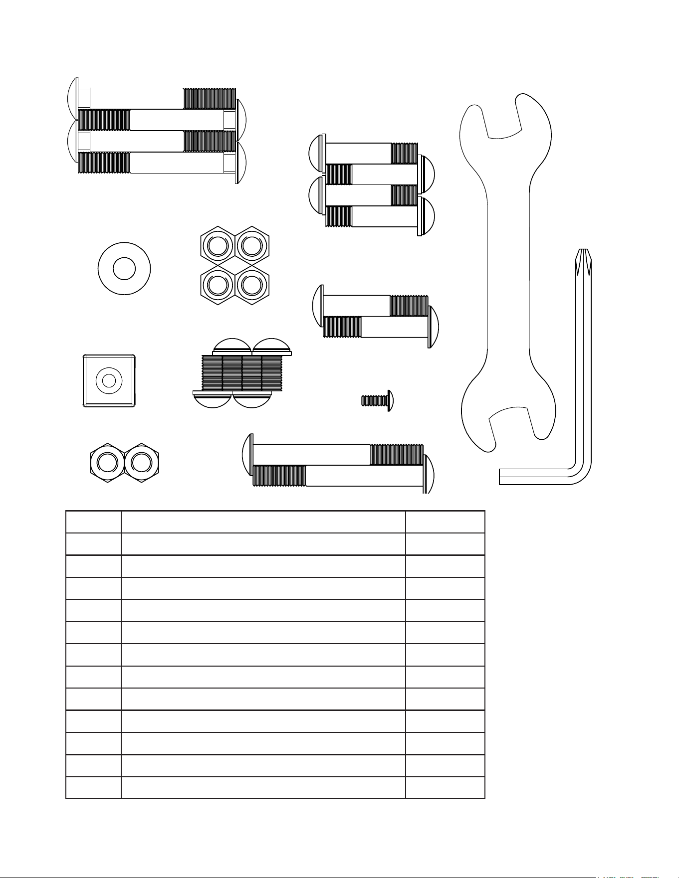
SB120 Assembly Pack Checklist
No. Description Q’ty
15 Carriage bolt M8x60L 4
16 Allen bolt M8x40L 2
18 Allen bolt M8x35L 4
19 Allen bolt M8x65L 2
22 Crossed head self-tapping screw M4x10L 1
27 Limited bracket 1
30 Domed nut M8x16t 4
31 Nut M8x8t 2
32 Allen screw M8x15L 4
33 Curved washer φ8.5xφ20x1.5t 8
72 Multifunctional wrench 1
73 Allen key 1
#18. M8 x 35L
(4 pcs)
#15. M8 x 60L
(4 pcs)
#30. M8 x 16t
(4 pcs)
#33. 8.5 x 20
x 1.5t (8 pcs)
#27. (1 pc)
#31. M8
(2 pcs)
#32. M8 x 15L
(4 pcs)
#16. M8 x 40L
(2 pcs)
#22. M4 x 10L
(1 pc)
#19. M8 x 65L
(2 pcs)
#72.
13mm/15mm
(1 pc)
#73. 5mm
(1 pc)
8
SB120 Recumbent Bike
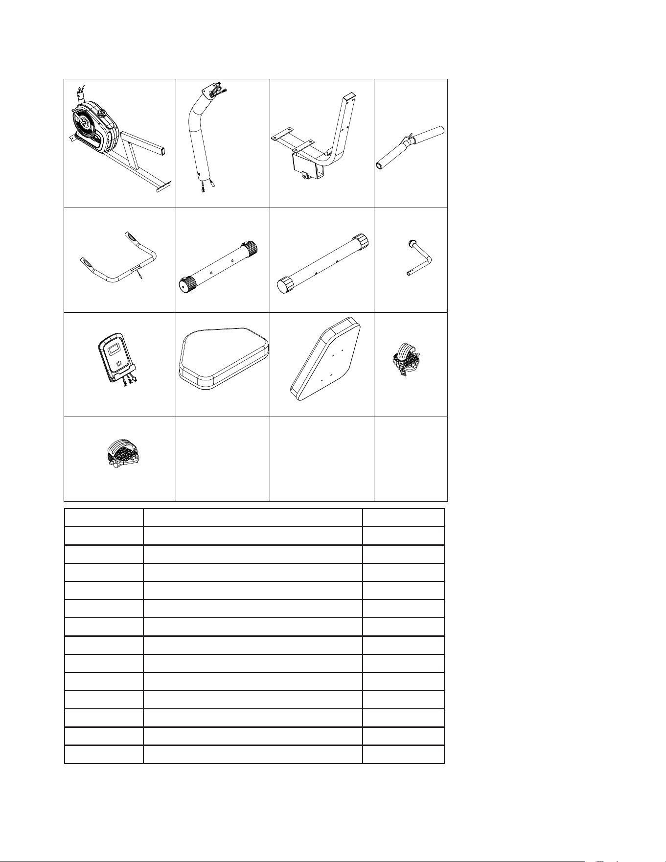
SB120 Parts Checklist
NO. 01 NO. 02 NO. 03 NO. 04
NO. 05 NO. 06 NO. 07 NO. 08
NO. 24 NO. 25 NO. 26 NO. 28
NO. 29
PART NO. DESCRIPTION Q’TY
01 Main frame 1
02 Front post 1
03 Backrest support bracket 1
04 Front handlebar 1
05 Rear handlebar 1
06 Front stabilizer 1
07 Rear stabilizer 1
08 Adjusted bar 1
24 Console 1
25 Seat 1
26 Back cushion 1
28 Pedal (L) 1
29 Pedal (R) 1
SB120 Recumbent Bike
9
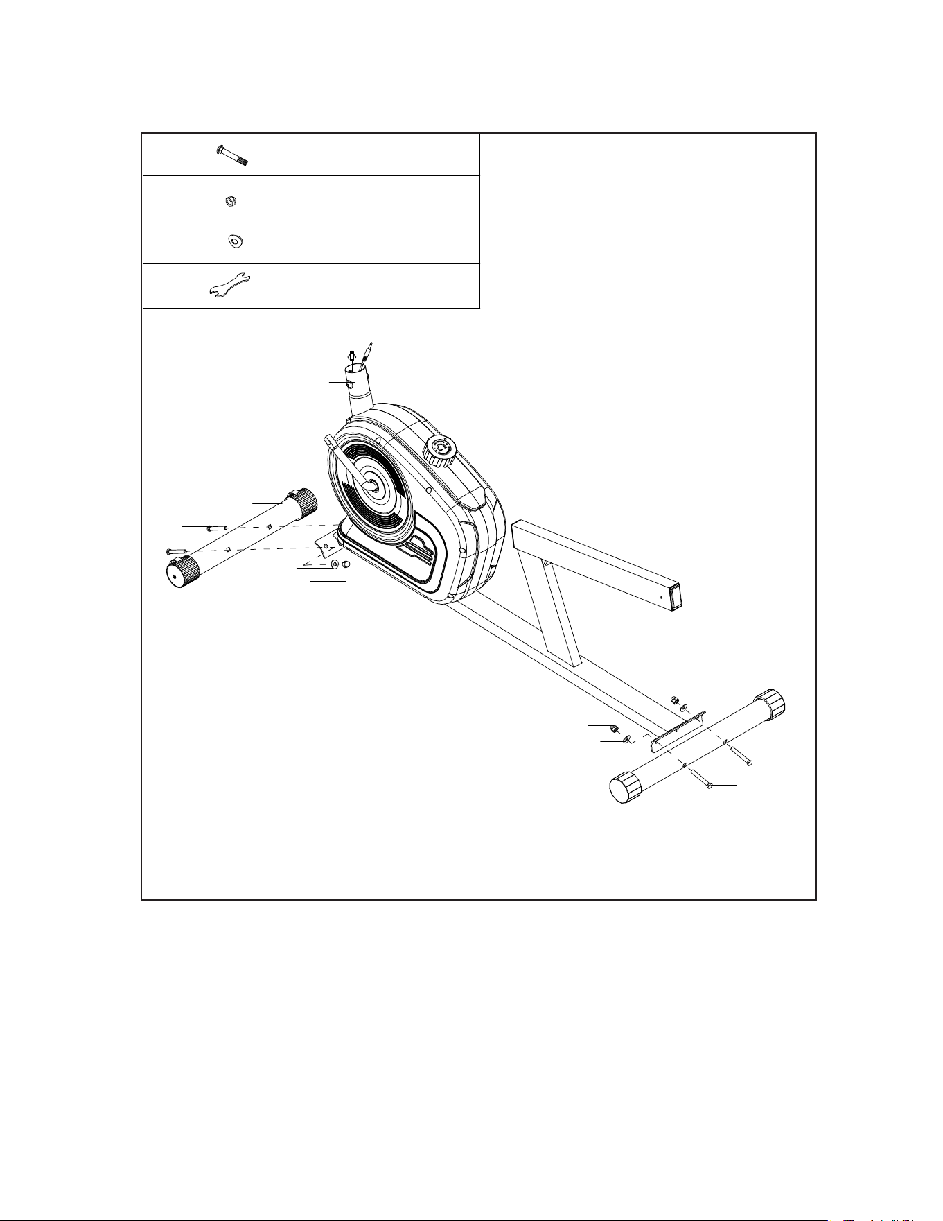
Stabilizers and Main Frame
1
1. Attach the Front Stabilizer (No. 06) to Main Frame (No. 01) using 2 Carriage
Bolts (No. 15), 2 Curved Washers (No. 33) and 2 Domed Nuts (No. 30).
2. Attach Rear Stabilizer (No. 07) to Main Frame (No. 01) using with 2 Carriage
Bolts (No. 15), 2 Curved Washers (No. 33) and 2 Domed Nuts (No. 30).
01
06
15
30
30
33
15
07
33
15
30
33
72
4pcs
4pcs
4pcs
M8 x 60L
M8
8.5 x 20 x 1.5t
Wrench
10
SB120 Recumbent Bike
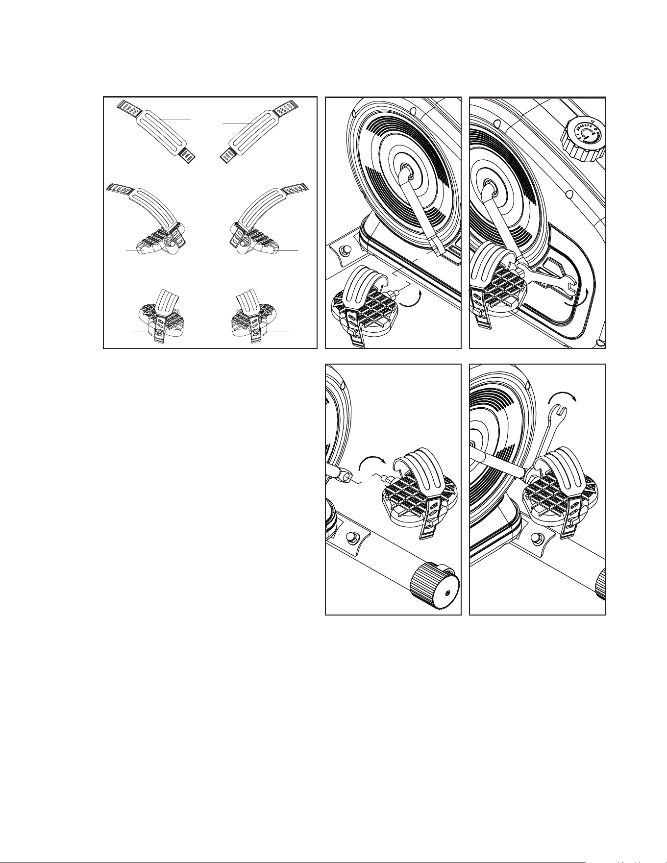
Installing the Pedals
2
1. Attach the (L) Strap to the Left
Pedal (No. 28), and adjust the
strap to the length you need.
Use the same method to attach
the (R) Strap to the Right Pedal
(No. 29).
2. Connect Left Pedal (No. 28) to
the left side of Crank w/ Pulley
(No. 35), twist it counterclockwise
to tighten.
3. Connect the Right Pedal (No.
29) to the right side of Crank w/
Pulley (No. 35), twist it clockwise
to tighten.
Note that the straps should face outwards and the pedals should be mounted to
their respective sides to be functional.
L
28 29
29
28
R
SB120 Recumbent Bike
11
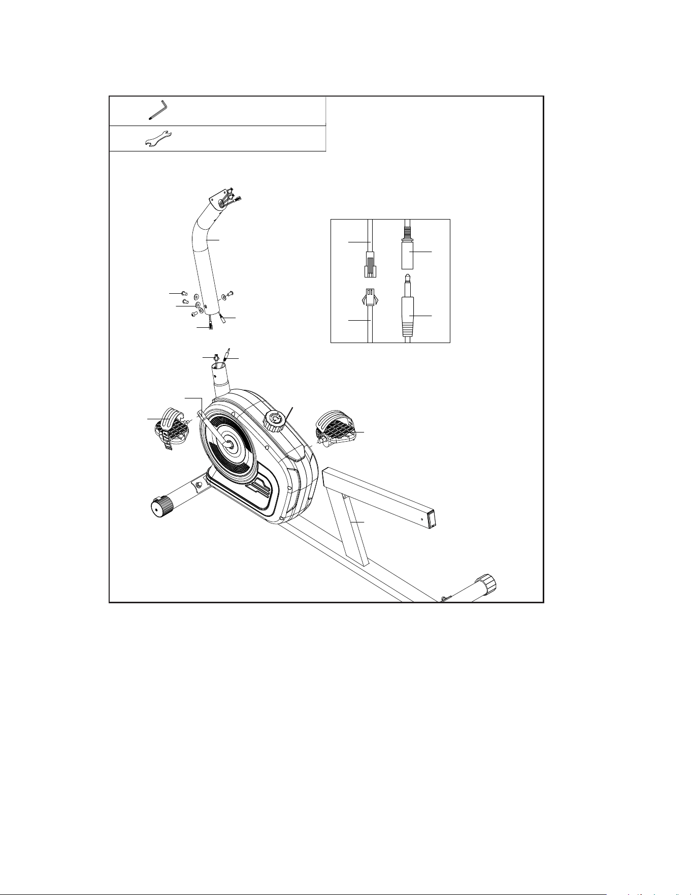
Tension and Pulse Wires
3
1. Remove the pre-installed 4 Allen Screws (No. 17) & 4 Arc Washers (No. 33) from
Front Post (No. 02) and connect the Upper Sensor Wire (No. 10) with the Lower
Sensor Wire (No. 11) (see g. 3.2).
2. Connect Upper Pulse Sensor Wire (No. 12) with Lower Pulse Sensor Wire (No. 13)
(see g. 3.3).
3. Insert the Front Post (No. 02) into the Main Frame (No. 01) and secure with 4 Allen
Bolts (No. 17) and 4 Curved Washers (No. 33).
Allen Key73
72
Wrench
10
02
12
13
17
33
10
11
35
28
29
01
12
13
11
Fig. 3.2
51
Fig. 3.3
12
SB120 Recumbent Bike
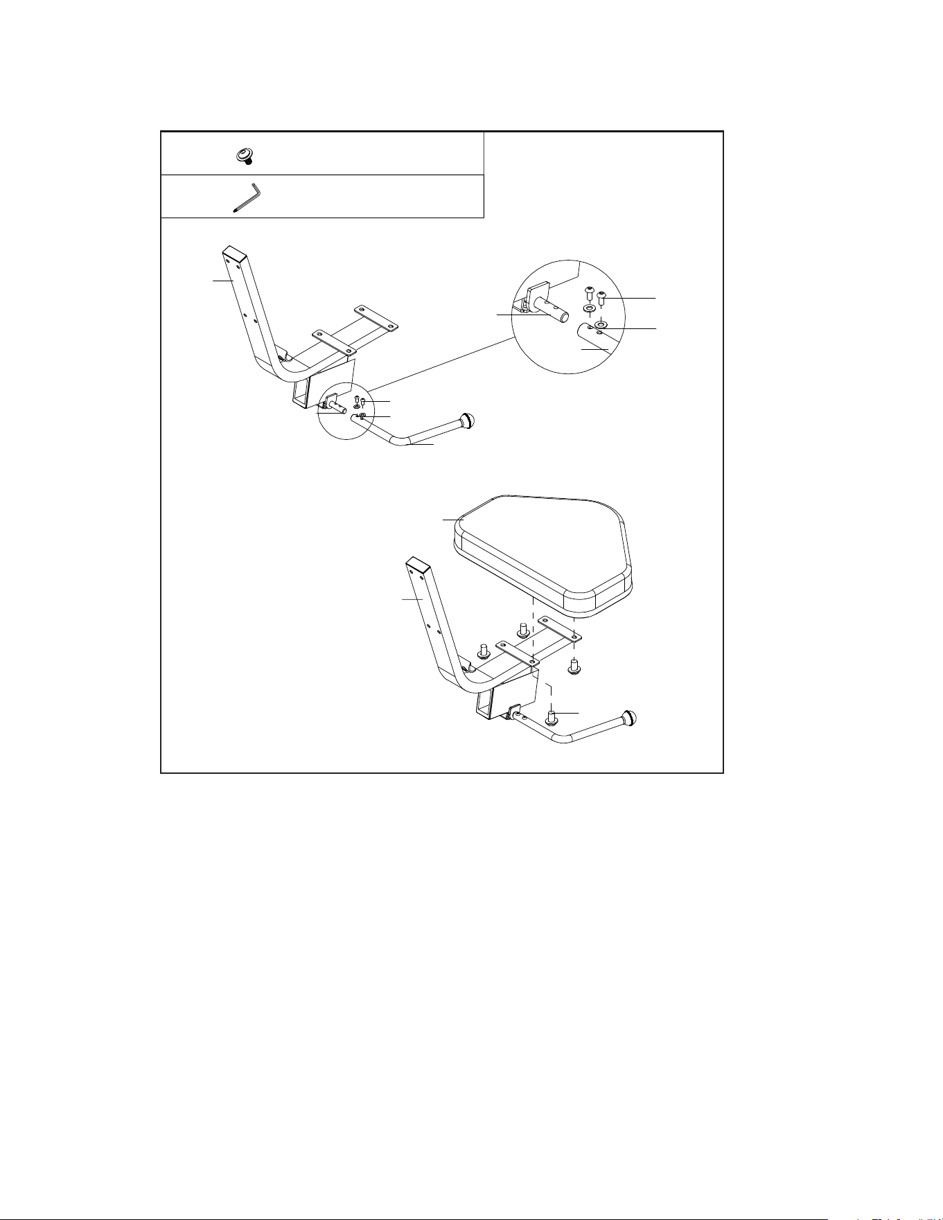
Assembling the Seat
4
1. Remove the pre-installed 2 Allen Bolts (No. 20) and 2 Flat Washers (No. 34)
from Connection Axle (No. 09).
2. Insert the Adjustable Bar (No. 08) into Connection Axle (No. 09) as shown
above, then tighten with 2 Allen Bolts (No. 20) and 2 Flat Washers (No. 34).
3. Attach the Seat (No. 25) to Backrest Support Bracket (No. 03) and tighten with
4 Allen Screws (No. 32).
32 4pcs M8 x 15L
73
03
09
20
34
08
08
34
20
09
03
25
32
Allen Key
SB120 Recumbent Bike
13
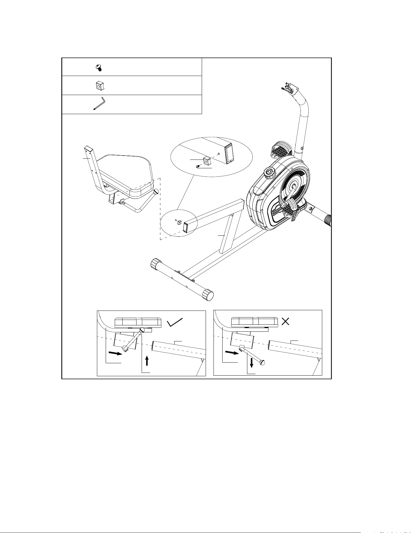
Attaching the Lower Seat
5
1. Lift up the Adjustable Bar (No. 08) and insert the Backrest Support Bracket
(No.3) into the Main Frame (No.1) as shown in the diagram above. Ensure
that the Adjustable Bar (No. 08) is pointing upright when inserting for proper
assembly.
2. Attach the Limited Bracket (No. 27) onto the Main Frame (No. 01) and tighten
with 1 Crossed Head Self-Tapping Screw (No. 22).
22 1 pc M4 x 10L
27 1 pc
73 Allen key
03
27
01
22
03
08
03
08
Yes
No
14
SB120 Recumbent Bike
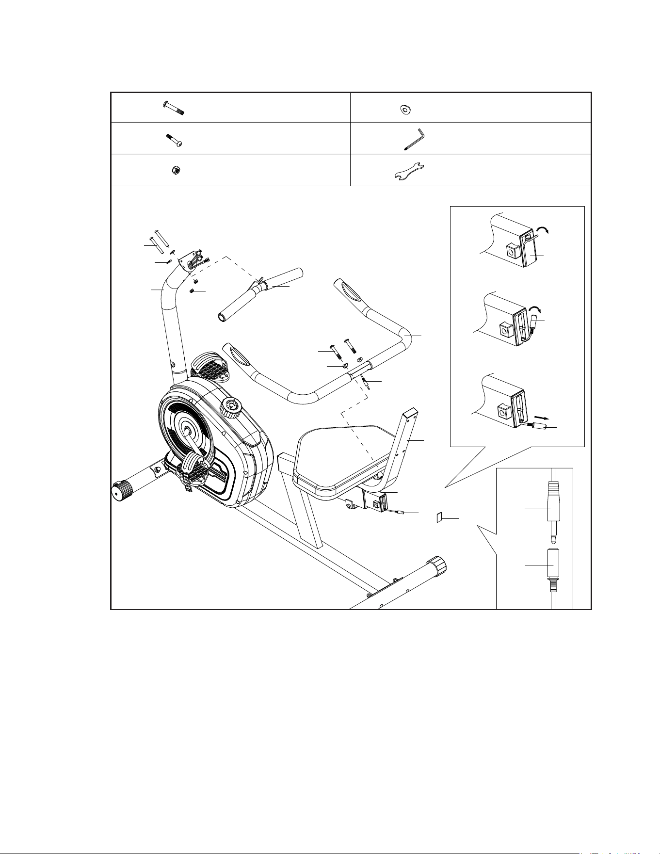
Attaching the Handlebars
6
1. Attach the Front Handlebar (No. 04) to the Front Post (No. 02), tighten with 2
Allen Bolts (No. 19) and 2 Curved Washers (No. 33) and 2 Nuts (No. 31).
2. Attach the Rear Handlebar (No. 05) to the Backrest Support Bracket (No. 03),
tighten 2 Allen Bolts (No. 16) and 2 Curved Washers (No. 33).
3. Remove the Sticker (No. 36) from the Main Frame (No. 01), gently pull the
Middle Pulse Sensor Wire (No. 14) out of the upright and connect it to the
Lower Pulse Sensor Wire (No. 21).
16
19
31
2 pcs
2 pcs
2 pcs
M8 x 40L
M8 x 65L
M8
33
73
72
4 pcs 8.5 x 20 x 1.5t
Allen Key
Wrench
19
33
31
02
04
16
33
21
05
36
14
01
03
14
36
14
21
14
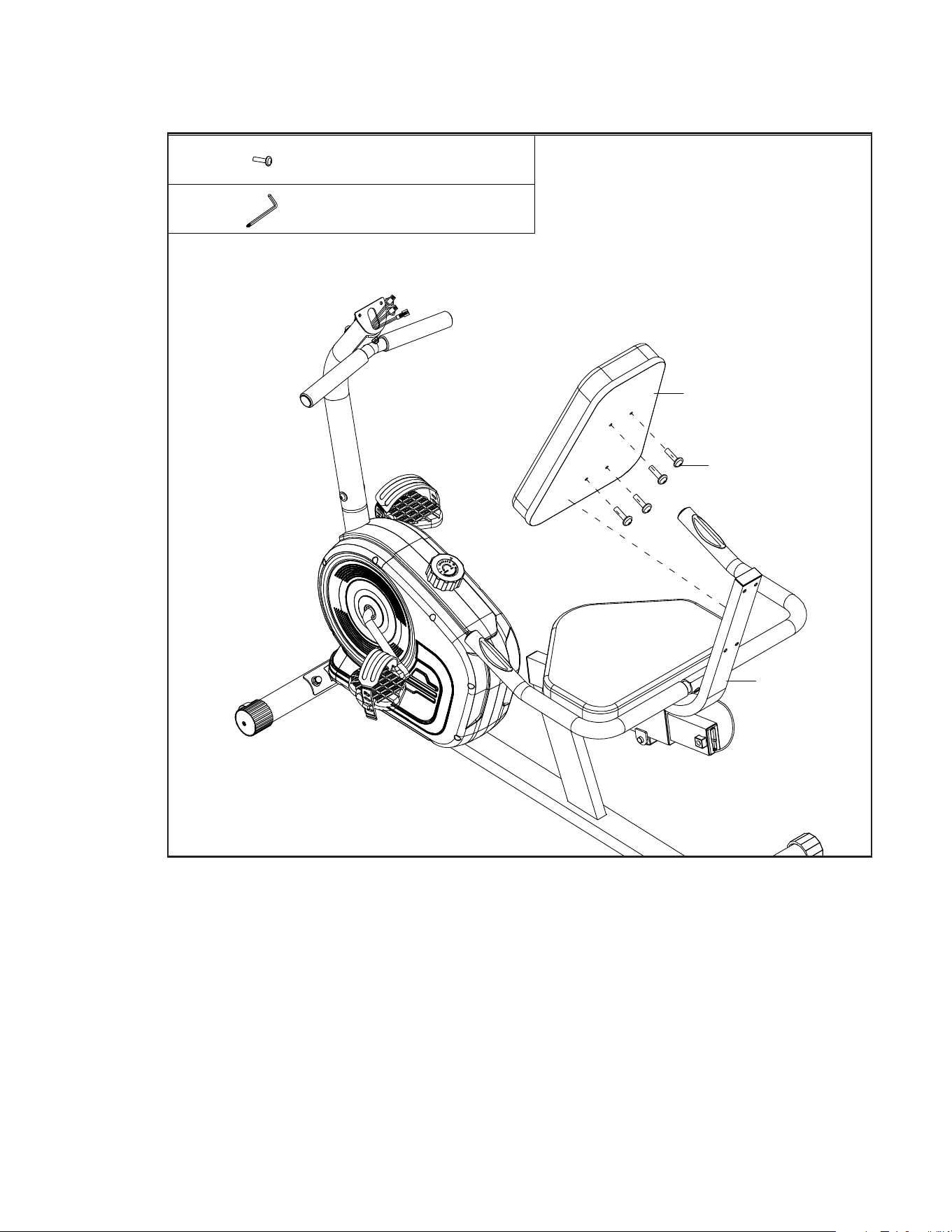
SB120 Recumbent Bike
15
Attaching the Seat Back
7
1. Attach the Back Cushion (No. 26) to the Backrest Support Bracket (No. 03),
tighten with 4 Allen Bolts (No. 18).
18 4 pcs
M8 x 35L
73
26
03
18
Allen Key
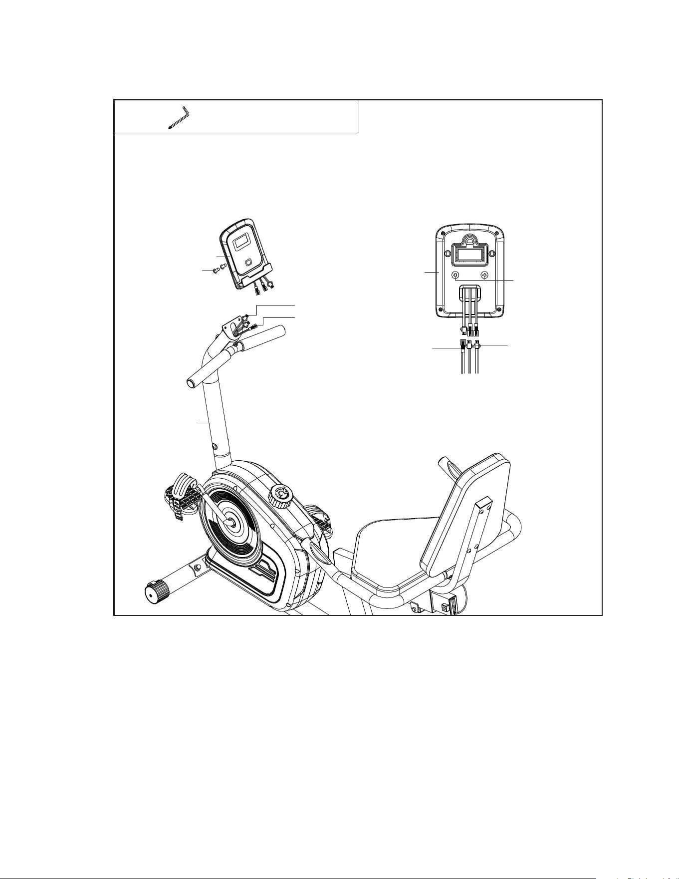
16
SB120 Recumbent Bike
Attaching the Console
8
1. Remove the pre-installed 2 Crossed Head Screws (No. 23) from the back of
Console (No. 24).
2. Connect the Upper Sensor Wire (No. 10) and the Upper Pulse Sensor Wire
(No. 12) to the Console (No. 24), and then attach the Console (No. 24) to the
Front Post (No. 02), secure with 2 Crossed Head Screws (No. 23).
73
Allen Key
24
23
12
10
02
10
12
23
24
*NOTE: CHECK TO ENSURE THAT ALL BOLTS AND NUTS ARE TIGHTENED BEFORE USING
THE MACHINE.

SB120 Recumbent Bike
17
Final Considerations
• Tighten all bolts/nuts securely to complete assembly.
• The bike can be cleaned with a damp cloth and mild non-abrasive detergent. Do not use solvents.
• Make sure to tighten both pedals securely to the pedal crank arms as instructed.
• Store the bike Indoors. Excessive moisture can cause rust to the frame and damage to the
electronics.
• Place the bike in a such a way that there is room on all side of the bike to safely mount and dismount.
We recommend a minimum of 2 feet all around the bike to safely access the bike.
Adjusting Resistance
• Use the Tension Knob (No. 51) on to adjust the resistance. Level 1 is
the minimum resistance.
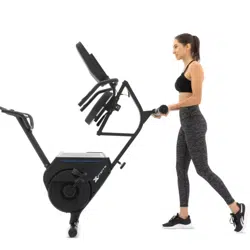
Transporting the Bike
• There is a set of transport wheels on the Front Stabilizer (No. 6). To move the bike
carefully tilt the handlebar forwards and roll away.
18
SB120 Recumbent Bike
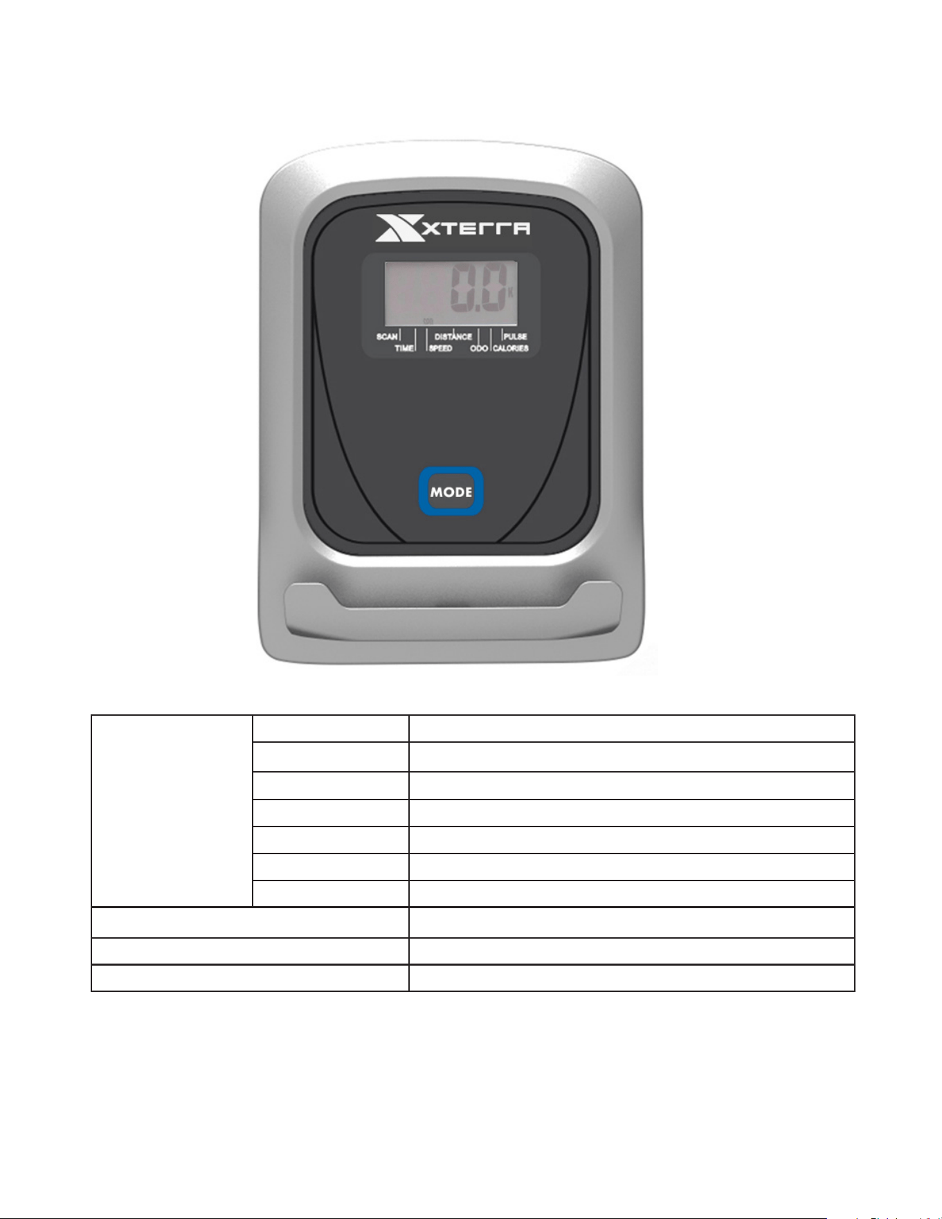
SB120 Console
Getting Familiar with the Control Panel
Exploring Your New Bike
Functions SCAN Every 6 seconds
TIME 0:00 ~ 99:59
SPEED 0.0 ~ 999.9 KM/H (MILE/H)
DISTANCE 0.00 ~ 999.9 KM (MILE)
CALORIES 0.0 ~ 999.9 CAL
ODOMETER 0.0 ~ 9999 KM (MILE)
PULSE 40 ~ 240 BPM
BATTERY TYPE 2 AAA or UM 4
OPERATING TEMPERATURE 0°C ~ +40°C, 32˚F ~ 104˚F
STORAGE TEMPERATURE -10°C ~ +60°C, 14˚F ~ 140˚F
The console turns on when you start pedaling or when you press a key.
The console turns off automatically after 4 minutes of inactivity.

SB120 Recumbent Bike
19
Button Functions
MODE: Press to select functions. Press the button and hold for two seconds to reset all
functions to zero, except ODOMETER.
Key Functions
SCAN: Press MODE button until “▼” appears at SCAN position, the console displays: time,
speed, distance, calories, odometer and pulse, in sequence for 6 seconds at a time
TIME: Displays the time from exercise start to the end
SPEED: Displays the current speed
DISTANCE: Displays the distance from exercise start to the end
CALORIES: Displays the calories burned from the exercise start to the end.
The calorie readout is an estimate for an average user. It should be used only as comparison
between workouts on this unit.
ODOMETER: Display the total accumulated distance you have traveled. The odometer does
not reset unless you remove the batteries.
PULSE: Displays an average current heart beat rate in beats per minute (BPM). To use this
feature, place hands on the pulse grips and hold for 6 ~ 7 seconds to get a more accurate
reading.
Please note that due to contact delay, the heart rate will be higher than the actual heart
rate during the rst 2 ~ 3 seconds of measurement, then will return to normal level. The
measurement value shouldn’t be regarded as the basis of medical treatment.

20
SB120 Recumbent Bike
Troubleshooting
Problem Solution
When display shows all 0’s, faded numbers,
incomplete numbers or blank screen
• Remove the computer and check
the wire that comes from the computer is
properly connected to the wire that comes
from the Upright.
• Check that the batteries are correctly
positioned and are in proper contact with the
battery springs.
• The batteries in the computer may
be dead. Remove and replace with new
batteries.

SB120 Recumbent Bike
21
Manufacturer’s Limited Warranty
Effective September 10, 2019 - SB120 Recumbent Bike LIMITED WARRANTY
XTERRA Fitness Inc. warrants all its home use Recumbent Bike parts for a period of time listed below, from the date of retail sale, as
determined by a sales receipt or in the absence of a sales receipt, eighteen (18) months from the original factory shipping date. XTERRA
Fitness’s
responsibilities include providing new or remanufactured parts, at XTERRA Fitness’s option, and technical support to our independent
dealers and servicing organizations. In the absence of a dealer or service organization, these warranties will be administered by XTERRA
Fitness directly to a consumer. The warranty period applies to the following components:
Home Use Limited WARRANTY
NORMAL RESPONSIBILITIES OF THE CONSUMER
This warranty applies only to products in ordinary household use. The consumer is responsible for the items listed below:
1. The warranty registration card must be completed and returned to the address listed on the card within 10 days of the original purchase
to validate the manufacturer’s limited warranty or register online at http://www.xterratnessstore.com/warrantyreg.html.
2. Proper use of the Recumbent Bike in accordance with the instructions provided in this manual, including maintenance.
3. Proper connection to a power supply of sufcient voltage, replacement of blown fuses, repair of loose connections or defects in house/
facility wiring.
4. Expenses for making the Recumbent Bike accessible for servicing, including any item that was not part of the Recumbent Bike at the
time it was shipped from the factory.
5. Damages to the Recumbent Bike nish during shipping, installation or following installation.
EXCLUSIONS
This warranty does not cover the following:
1. CONSEQUENTIAL, COLLATERAL, OR INCIDENTAL DAMAGES SUCH AS PROPERTY DAMAGE AND INCIDENTAL EXPENSES
RESULTING FROM ANY BREACH OF THIS WRITTEN OR ANY IMPLIED WARRANTY. Note: Some states do not allow the exclusion
or limitation of incidental or consequential damages, so this limitation or exclusion may not apply to you.
2. Service call reimbursement to the consumer. Service call reimbursement to the dealer that does not involve malfunction or defects in
workmanship or material, for units that are beyond the warranty period, for units that are beyond the service call reimbursement period,
for Recumbent Bikes not requiring component replacement, or Recumbent Bikes not in ordinary household use.
3. Damages caused by services performed by persons other than authorized XTERRA Fitness service companies, use of parts other than
original XTERRA Fitness parts, or external causes such as alterations, modications, abuse, misuse, accident, improper maintenance,
inadequate power supply, or acts of God.
4. Products with original serial numbers that have been removed or altered.
5. Products that have been; sold, transferred, bartered, or given to a third party.
6. Products that are used as store display models.
7. Products that do not have a warranty registration on le at XTERRA Fitness, Inc. XTERRA Fitness reserves the right to request proof of
purchase if no warranty record exists for the product.
8. Product use in any environment other than a residential setting.
9. THIS WARRANTY IS EXPRESSLY IN LIEU OF ALL OTHER WARRANTIES EXPRESSED OR IMPLIED, INCLUDING THE
WARRANTIES OF MERCHANTABILITY AND/OR FITNESS FOR A PARTICULAR PURPOSE.
SERVICE
Keep your bill of sale. Twelve (12) months from the date on the bill of sale or eighteen (18) months from the date of factory shipping as
determined by the serial number establishes the warranty period should service be required. If service is performed, it is in your best interest
to obtain and keep all receipts. This written warranty gives you specic legal rights. You may also have other rights that vary from state to
state. Service under this warranty must be obtained by following these steps, in order:
1. Contact your selling authorized XTERRA Fitness dealer. OR
2. Contact your local authorized XTERRA Fitness service organization.
3. If there is a question as to where to obtain service, contact our service department at (800) 258-8511.
4. XTERRA Fitness’s obligation under this warranty is limited to repairing or replacing, at XTERRA Fitness’s option, the product through
one of our authorized service centers. All repairs must be preauthorized by XTERRA Fitness. If the product is shipped to a service
center freight charges to and from the service center will be the customer’s responsibility. For replacement parts shipped while the
product is under warranty, the customer will be responsible for shipping and handling charges. For in-home service, the customer
will be responsible for a trip charge. There will be an additional trip charge if the customer is located over 100 miles from the nearest
service center.
5. The owner is responsible for adequate packaging upon return to XTERRA Fitness. XTERRA Fitness is not responsible for damages in
shipping. Make all freight damage claims with the appropriate freight carrier. DO NOT SHIP ANY UNIT TO OUR FACTORY WITHOUT
A RETURN AUTHORIZATION NUMBER. All units arriving without a return authorization number will be refused.
6. For any further information, or to contact our service department by mail, send your correspondence to:
Product features or specications as described or illustrated are subject to change without notice. All warranties are made by
XTERRA Fitness, Inc. This warranty applies only in the 48 contiguous United States. NOTE: This does not apply to Alaska or Hawaii.
XTERRA Fitness, Inc.
P.O. Box 2037
Jonesboro, AR 72402-2037
Frame
1 Year
Parts Labor
1 Year None

3000 Nestle Road Jonesboro, AR 72401 - Phone: 870-336-4286 - Fax: 870-935-7611
www.xterrafitness.com
©2019 All Rights Reserved. SB120 Owner’s Manual