Loading ...
Loading ...
Loading ...
9
CONTROL SCONTROL S
DOLBY DIGITAL
OUT
(OPTICALL)
IN
OUT
SD/HD
S VIDEO
S-LINK/
CONTROL S
OUT
S-LINK/
CONTROL S
IN
VIDEO
AUDIO
L
R
R
VIDEO
L
AUDIO
VHF/UHF
AUX
(MONO)
IN OUT
VIDEO 1 VIDEO 3 VIDEO 4 (DVD) SELECT
VHF/UHF
(DTV)
Y
P
B
PR
LINE
OUT
OUT
IN
AUDIO R AUDIO L VIDEO
S VIDEO
VHF/UHF
LINE
IN
S VIDEO
VIDEO
VIDEO OUT
3
Y
P
B
P
R
R
G
B
HD
VD
AUDIO OUT
L
(MONO)
R
1
2
4
1
2
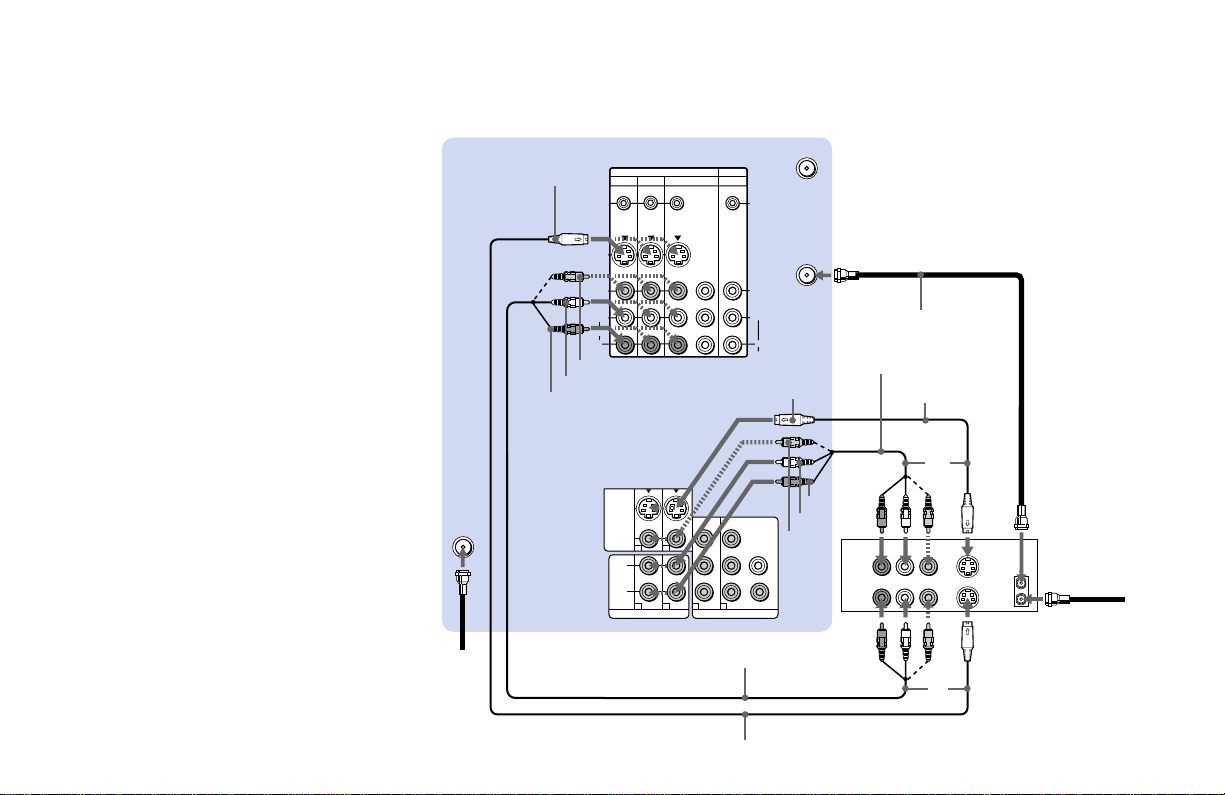
Disconnect all power sources before making any connections.
Connecting an antenna/cable TV
system to a VCR
1 Attach the coaxial cable from the roof
antenna to VHF/UHF (DTV) on the TV’s
lower panel.
2 Attach the coaxial cable from the
incoming cable connection or antenna to
IN on the VCR.
3 Using a coaxial cable, connect OUT on the
VCR to VHF/UHF on the TV’s upper
panel.
4 Using AUDIO and S VIDEO* cables,
connect AUDIO and S VIDEO OUT on the
VCR to AUDIO and S VIDEO IN on the
TV’s upper panel (White-AUDIO Left,
Red-AUDIO Right).
5 Using AUDIO and S VIDEO* cables,
connect AUDIO and S VIDEO IN on the
VCR to AUDIO and S VIDEO OUT on the
TV’s lower panel.
* If your VCR is not equipped with S VIDEO, use a
VIDEO cable (yellow) instead of the S VIDEO
cable.
Note:
• If you are connecting a monaural VCR,
connect only the single audio output to
the left (MONO) input on the projection
TV.
1
VMC-810S/820S (not supplied)
YC-15V/30V (not supplied)
VCR
2
Cable/
Antenna
4
3
Coaxial cable
YC-15V/30V
(not supplied)
S VIDEO
AUDIO R
Roof
antenna
S VIDEO
(Rear of projection TV)
AUDIO-L
AUDIO-R
5
VIDEO
VIDEO
AUDIO L
VMC-810S/820S
(not supplied)
Loading ...
Loading ...
Loading ...