
© 1999 by Sony Corporation
3-866-010-11 (2)
HDTV Projection TV
Operating Instructions
KWP-65HD1
WARNING
To prevent fire or shock
hazard, do not expose the TV
to rain or moisture.
This symbol is intended to alert the user to
the presence of uninsulated “dangerous
voltage” within the product’s enclosure that
may be of sufficient magnitude to constitute
a risk of electric shock to persons.
This symbol is intended to alert the user to
the presence of important operating and
maintenance (servicing) instructions in the
literature accompanying the appliance.
CAUTION
To prevent electric shock, do not use this polarized AC
plug with an extension cord, receptacle or other
outlet unless the blades can be fully inserted to
prevent blade exposure.
CAUTION
When using TV games, computers, and similar products
with your projection TV, keep the brightness and
contrast functions at low settings. If a fixed (non-
moving) pattern is left on the screen for long periods
of time especially at a high brightness or contrast
setting, the image can be permanently imprinted onto
the screen. These types of imprints are not covered by
your warranty because they are the result of misuse.
Note on Caption Vision
This television receiver provides display of television
closed captioning in accordance with §15.119 of the
FCC rules.
Note on convergence adjustment
Before you use your projection TV, make sure to adjust
convergence. For details, see page 27.
Note to CATV system installer
This reminder is provided to call the CATV system
installer’s attention to Article 820-40 of the NEC that
provides guidelines for proper grounding and, in
particular, specifies that the cable ground shall be
connected to the grounding system of the building, as
close to the point of cable entry as practical.
Use of this television receiver for other than private
viewing of programs broadcast on UHF or VHF or
transmitted by cable companies for the use of the
general public may require authorization from the
broadcaster/cable company and/or program owner.
NOTIFICATION
This equipment has been tested and found to comply
with the limits for a Class B digital device pursuant to
Part 15 of the FCC Rules. These limits are designed to
provide reasonable protection against harmful
interference in a residential installation. This
equipment generates, uses, and can radiate radio
frequency energy and, if not installed and used in
accordance with the instructions, may cause harmful
interference with radio communications. However,
there is no guarantee that interference will not occur
in a particular installation. If this equipment does
cause harmful interference to radio or television
reception, which can be determined by turning the
equipment off and on, the user is encouraged to try to
correct the interference by one or more of the
following measures:
• Reorient or relocate the receiving antennas.
• Increase the separation between the equipment and
receiver.
• Connect the equipment into an outlet on a circuit
different from that to which the receiver is
connected.
• Consult the dealer or an experienced radio/TV
technician for help.
You are cautioned that any changes or
modifications not expressly approved in this
manual could void your authority to operate this
equipment.
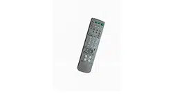
This document is for the remote control RM-Y904
MODEL: KWP-65HD1
Please keep this notice with the instruction manual.
Manufactured under license from Dolby Laboratories.
“Dolby,“ “Pro Logic” and the double-D symbol a are
trademarks of Dolby Laboratories.
Confidential Unpublished Works.
1992–1997 Dolby
Laboratories, Inc. All rights reserved.
CAUTION
RISK OF ELECTRIC SHOCK
DO NOT OPEN
ATTENTION
RISQUE DE CHOC ELECTRIQUE,
NE PAS OUVRIR
PRECAUCION
RIESGO DE CHOQUE ELECTRICO
NO ADRIR
CAUTION : TO REDUCE THE RISK OF ELECTRIC SHOCK,
DO NOT REMOVE COVER
(
OR BACK
)
.
NO USER-SERVICEABLE PARTS INSIDE.
REFER SERVICING TO QUALIFIED SERVICE PERSONNEL.
NO ABRIR
Printed in Japan
If, after reading these instructions, you have
additional questions related to the use of your
Sony projection TV, please call one of the
following numbers (English only).
Customers in the continental United States
contact the Direct Response Center at:
1-800-222-SONY (7669)
Customers in Canada contact the
Customer Relations Center at:
(416) 499-SONY (7669)
© 1999 by Sony Corporation
3-866-010-11 (2)
HDTV Projection TV
Operating Instructions
KWP-65HD1
WARNING
To prevent fire or shock
hazard, do not expose the TV
to rain or moisture.
This symbol is intended to alert the user to
the presence of uninsulated “dangerous
voltage” within the product’s enclosure that
may be of sufficient magnitude to constitute
a risk of electric shock to persons.
This symbol is intended to alert the user to
the presence of important operating and
maintenance (servicing) instructions in the
literature accompanying the appliance.
CAUTION
To prevent electric shock, do not use this polarized AC
plug with an extension cord, receptacle or other
outlet unless the blades can be fully inserted to
prevent blade exposure.
CAUTION
When using TV games, computers, and similar products
with your projection TV, keep the brightness and
contrast functions at low settings. If a fixed (non-
moving) pattern is left on the screen for long periods
of time especially at a high brightness or contrast
setting, the image can be permanently imprinted onto
the screen. These types of imprints are not covered by
your warranty because they are the result of misuse.
Note on Caption Vision
This television receiver provides display of television
closed captioning in accordance with §15.119 of the
FCC rules.
Note on convergence adjustment
Before you use your projection TV, make sure to adjust
convergence. For details, see page 27.
Note to CATV system installer
This reminder is provided to call the CATV system
installer’s attention to Article 820-40 of the NEC that
provides guidelines for proper grounding and, in
particular, specifies that the cable ground shall be
connected to the grounding system of the building, as
close to the point of cable entry as practical.
Use of this television receiver for other than private
viewing of programs broadcast on UHF or VHF or
transmitted by cable companies for the use of the
general public may require authorization from the
broadcaster/cable company and/or program owner.
NOTIFICATION
This equipment has been tested and found to comply
with the limits for a Class B digital device pursuant to
Part 15 of the FCC Rules. These limits are designed to
provide reasonable protection against harmful
interference in a residential installation. This
equipment generates, uses, and can radiate radio
frequency energy and, if not installed and used in
accordance with the instructions, may cause harmful
interference with radio communications. However,
there is no guarantee that interference will not occur
in a particular installation. If this equipment does
cause harmful interference to radio or television
reception, which can be determined by turning the
equipment off and on, the user is encouraged to try to
correct the interference by one or more of the
following measures:
• Reorient or relocate the receiving antennas.
• Increase the separation between the equipment and
receiver.
• Connect the equipment into an outlet on a circuit
different from that to which the receiver is
connected.
• Consult the dealer or an experienced radio/TV
technician for help.
You are cautioned that any changes or
modifications not expressly approved in this
manual could void your authority to operate this
equipment.
This document is for the remote control RM-Y904
MODEL: KWP-65HD1
Please keep this notice with the instruction manual.
Manufactured under license from Dolby Laboratories.
“Dolby,“ “Pro Logic” and the double-D symbol a are
trademarks of Dolby Laboratories.
Confidential Unpublished Works.
1992–1997 Dolby
Laboratories, Inc. All rights reserved.
CAUTION
RISK OF ELECTRIC SHOCK
DO NOT OPEN
ATTENTION
RISQUE DE CHOC ELECTRIQUE,
NE PAS OUVRIR
PRECAUCION
RIESGO DE CHOQUE ELECTRICO
NO ADRIR
CAUTION : TO REDUCE THE RISK OF ELECTRIC SHOCK,
DO NOT REMOVE COVER
(
OR BACK
)
.
NO USER-SERVICEABLE PARTS INSIDE.
REFER SERVICING TO QUALIFIED SERVICE PERSONNEL.
NO ABRIR
Printed in Japan
If, after reading these instructions, you have
additional questions related to the use of your
Sony projection TV, please call one of the
following numbers (English only).
Customers in the continental United States
contact the Direct Response Center at:
1-800-222-SONY (7669)
Customers in Canada contact the
Customer Relations Center at:
(416) 499-SONY (7669)
HDTV
2
5
8
0
1
4
7
3
6
9
TV/VIDEO DTV ANT
TV ANT
ENTER
MENU
RESET
VOL CH
MUTING
TV
OFF
WIDE MODE
TV/DBS
PICTURE
MODE
JUMP GUIDE
DISPLAY
VIDEO AUDIO
ALTERNATE
POWER
SLEEP
DVD/
VTR
DBS/
CABLE
FUNCTION
DVD/VTR
DBS/CABLE
TV
CC
2
5
8
1
4
7
3
6
9
MUTING
VTR123DVD/MDP
TV
POWER
FUNCTION
DVD/VTRDBS/CABLE
TV
MTS
AUDIO SWAP
FREEZEPOSITION
DVD MENU
TITLECODE SET
REC
SLEEP
DVD/
VTR
DBS/
CABLE
TV/VIDEO DTV ANT
TV ANT
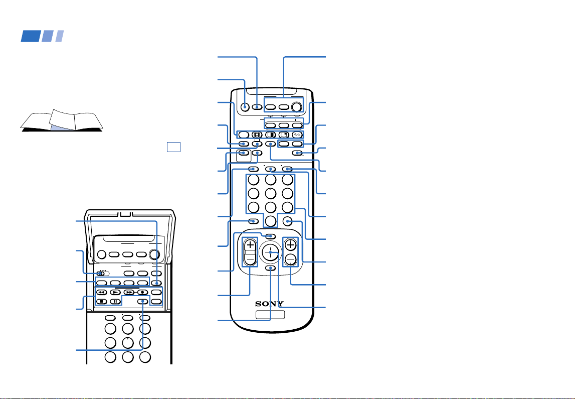
In the instructions that follow, we will
refer to the buttons on your remote control.
Keep this flap unfolded and use this page
for reference.
Getting to know the buttons on the
remote control
Names of the buttons on the remote control are
presented in different colors to represent the
available functions.
Button color
Transparent .... Press to select the component
you want to control; e.g. VTR
(VCR)/MDP/DVD Player,
DBS (Direct Broadcast
Satellite)/CABLE, or projection
TV.
Green ............... Buttons relevant to power
operations, like turning the
projection TV, DBS/CABLE, or
VTR (VCR)/MDP/DVD Player
on or off
Label color
White ............... TV/VTR (VCR)/MDP/DVD
Player/DBS (Direct Broadcast
Satellite)/CABLE operation
buttons
Yellow.............. PIP, P&P, and CHANNEL
INDEX operation buttons
Blue .................. DBS operation buttons
Pink .................. DVD Player operation buttons
For a detailed explanation of most buttons, see
“Watching Digital TV” on page 28, or
“Watching Conventional TV” on page 36.
Remote Control
SLEEP
(pages 29,37)
PIP/P&P/CHANNEL
INDEX (pages 40–45)
CC (page 38)
JUMP (pages 28,37)
MENU
(pages
32,46)
VOL +/–
(pages
28,36)
RESET
(pages
47,49)
POWER
(pages
28,36,73,74)
FUNCTION
(pages
28,36,72,74)
TV/VIDEO
(pages
29,38)
GUIDE
(page 31)
0–9 buttons
(pages 28,36)
ENTER (pages
28,36,72)
CH +/–
(pages 28,36)
Joystick
(page 23)
CODE SET
(pages 72,74)
VTR1/2/3/DVD/
MDP switch
(page 72)
MTS (page 38)
MUTING
(pages 29,37)
WIDE MODE
(pages 30,39)
TV/DBS/
PICTURE MODE
(pages 29,47)
• (dot)
button
(page 28)
VCR/DVD/MDP
operation
buttons
(page 73)
PIP/P&P/
CHANNEL INDEX
(pages 40-45)
ALTERNATE
(VIDEO/
AUDIO)
*
DISPLAY
(pages 29,31,37)
TV ANT
(page
23,36)
DTV ANT
(pages
23,26,28)
*Note:
• The ALTERNATE (VIDEO/AUDIO) buttons do not
function with this projection TV.

Table of Contents
Connecting a VCR and projection TV
to a cable box ....................................10
Connecting a DBS (Direct Broadcast
Satellite) receiver.............................. 11
Connecting a DBS (Direct Broadcast
Satellite) receiver and a VCR .........12
Connecting a camcorder.....................13
Connecting two VCRs for tape
editing ...............................................14
Connecting a DVD Player without
component video output
connectors .........................................15
Connecting a DVD Player with
component video output
connectors .........................................16
Connecting an AV receiver.................17
Connecting an audio system .............18
Connecting an amplifier that supports
Dolby* Pro Logic/Dolby Digital
decoder..............................................19
Using the S-Link/CONTROL S
Function ................................................20
About the VIDEO 5 (HD) IN jacks ..........22
Basic Set Up
Using the Remote Control ........................23
Setting Up the Projection TV
Automatically ......................................24
Adjusting the Convergence Automatically
(AUTO FOCUS) ...................................27
Welcome! ........................................ 2
Using This Manual .......................... 2
Frequently Asked Questions.......... 3
Precautions...................................... 4
Installing and Connecting the
Projection TV
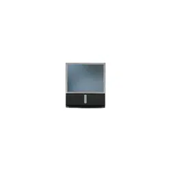
Carrying Your Projection TV......................5
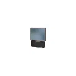
Installing the Projection TV........................5
Mounting the Supplied Rear Speakers.....6
Connector Types ..........................................6
Making Connections ...................................7
To receive DTV channels ......................7
Connecting directly to a cable or an
antenna................................................7
Cable or antenna....................................7
Cable and antenna.................................7
Connecting a cable box .........................8
Cable box and cable ..............................8
About the DOWN CONVERTER
switch ...................................................8
About the DTV I/O cable.....................8
Connecting an antenna/cable TV
system to a VCR.................................9
* Manufactured under license from Dolby
Laboratories.
“Dolby,“ “Pro Logic” and the double-D symbol a
are trademarks of Dolby Laboratories.
Confidential Unpublished Works. 1992–1997
Dolby Laboratories, Inc. All rights reserved.
Open Here For Table of Contents and Remote Control Graphics

Using Digital TV Features
Watching Digital TV ...................................... 28
Using the Wide Screen Mode....................... 30
Using the Program Guide to Select
Subchannels ............................................... 31
Learning Setup Menu Selection................... 32
Using the Setup Menu .................................. 33
Owner’s Record
The model and serial numbers are located at the rear of
the projection TV, below the Sony logo, on the sticker,
and also on the TV box (white label). Record these numbers
in the spaces provided below. Refer to them whenever
you call upon your Sony dealer regarding this product.
Model No.
Serial No.
KWP-65HD1
Using Conventional TV Features
Watching Conventional TV .......................... 36
Using the Wide Screen Mode....................... 39
Watching Two Programs at One Time —
PIP ............................................................... 40
Watching Two Programs at One Time —
P&P (Twin View
TM
).................................... 42
Using CHANNEL INDEX ............................ 44
Learning Menu Selection .............................. 46
Using the VIDEO Menu................................ 47
Using the AUDIO Menu ............................... 49
Adjusting the Speaker Volume for
Customized Surround Mode................... 51
Using the TIMER Menu ................................ 52
Using the WIDE SCREEN MODE
Menu ........................................................... 53
Using the CHANNEL SET UP Menu ......... 54
Setting and Selecting FAVORITE
CHANNEL ................................................. 57
Using the SET UP Menu ............................... 59
Using the PARENTAL CONTROL
Feature ........................................................ 64
What the Ratings Mean ................................ 70
Operating Video Equipment
Setting the Manufacturer's Code ................. 72
Operating a Cable Box or DBS Receiver
Setting the Manufacturer’s Code ................ 74
Troubleshooting ............................... 75
Specifications .................................... 78
Index ............................................... 79

2
Thank you for purchasing the Sony HDTV
Projection TV.
The features you will enjoy include:
• Built-in Digital Television (DTV) receiver,
enabling you to view digital television
programs and to enjoy the improved
audio/video quality that these programs
offer. This DTV receiver is designed for
use with terrestrial broadcast DTV system
only. (see “Frequently Asked Questions”
on page 3)
• WIDE SCREEN MODE, allowing you to
watch 4:3 normal broadcasts in wide
screen mode (16:9 aspect ratio).
• PARENTAL CONTROL, enabling you to
block programs that are unsuitable for
your children. (not available for DTV
programs)
• DRC (Digital Reality Creation), a
technology unique to Sony, allowing you
to obtain a finer, more detailed picture
with four-times higher density* than the
conventional NTSC picture. (not available
for DTV programs except for 480i)
* When you select WIDE ZOOM or ZOOM, the
DRC feature will work but the picture
density may not reach its full potential.
Welcome!
• MID (Multi Image Driver), a newly
developed device, allowing you to enjoy
the following features and, at the same
time, to use your projection TV easily.
(not available for DTV programs or VIDEO 5
(HD) IN jack)
- Picture & Picture (P&P) with zoom-in
function (Twin View
TM
)
- Picture-in-Picture (PIP)
- CHANNEL INDEX, allowing you to
view and choose from twelve
programs
- FAVORITE CHANNEL, allowing you to
view and choose from eight of your
favorite channels
• AUTO FOCUS, allowing you to adjust
convergence automatically.
• S-Link
TM
, allowing you to synchronize
some operations of your projection TV
with those of other Sony components.
• One Y/P
B/PR input for DVD Player
connection.
• Four AUDIO/VIDEO/S VIDEO inputs.
• VIDEO 5 (HD) IN jacks, switchable
between R/G/B/HD/VD and Y/P
B/PR
inputs, for receiving various HDTV
formats (up to 1080i) scheduled to
broadcast in the near future (not
compatible with a computer’s 5BNC (R/
G/B/HD/VD) video output connectors).
We recommend that you carefully review
the contents of the following four sections in
the order provided to ensure that you fully
understand the operation of your new
projection TV.
1 Installing and Connecting the Projection
TV
This section guides you through your
initial set up. It shows you how to install
your projection TV, to connect your new
components and to connect to the
antenna and cable.
2 Basic Set Up
This section teaches you the basic skills
needed to operate your new projection
TV, including Easy Set Up. It shows you
how to operate the remote control’s
special functions.
3 Using Digital Television (DTV) Features
This section shows you how to use your
remote control’s features to watch the
DTV programs. It also shows you how to
access on-screen menus and adjust your
projection TV’s settings for DTV.
4 Using Conventional Television Features
This section shows you how to operate
your projection TV and how to access on-
screen menus for conventional TV.
Instructions in this manual are written for the remote
control. Similar controls may be found on the projection
TV console.
Using This Manual
3
What is digital TV (DTV)?
Digital television (or “DTV”) refers to the new
over-the-air television broadcast standards
adopted by the Federal Communications
Commission in 1996. Developed by the
Advanced Television Systems Committee
(ATSC), a group of manufacturing companies,
these standards define the specifications for 18
digital broadcast formats.
There are six formats in the ATSC DTV
standard that are described as “High Definition
Television.” The remaining 12 video formats are
described as “Standard Definition Television.”
Although the technical aspects of these
standards are transparent to television viewers,
the benefits are as dramatic as those
experienced when digital music on compact
disc was introduced—probably even more so.
Your Sony DTV is capable of receiving all 18
formats of digital TV formats, which includes
high-definition.
What are the benefits of DTV?
For the television viewer, digital TV represents
one of the most significant advances in
television since color television replaced black
and white. Here are just a few of the benefits:
Dramatically superior picture quality, with up
to six times the picture detail of today’s analog
television.
Frequently Asked Questions
Multichannel digital sound, including Dolby
Digital sound.
Widescreen. DTV can provide the same type of
widescreen presentation you see in movie
theaters. The new screen size has a 16:9 width-
to-height (or “aspect”) ratio, compared to the
4:3 aspect ratio of today’s conventional
television. This means that digital broadcasts of
movies can be shown in their original format,
and no longer need to be “reformatted” for
television.
Do I need a special antenna to receive
digital television?
No. Initially, digital television will arrive
through a standard, over-the-air VHF/UHF
antenna, which means you can receive digital
broadcasts using the same terrestrial
(“rooftop”) antenna you currently use to receive
conventional programming. However, if you
currently receive your VHF/UHF
programming via cable, you will need to install
a VHF/UHF antenna in order to receive digital
programming.
Can this projection TV receive
conventional analog broadcasts that
are available today?
Yes. This projection TV is designed to receive
conventional analog broadcasts, cable TV, as
well as all formats of digital broadcasts. Of
course, you can also connect VCRs, DVD
players, digital broadcast (satellite) receivers,
and other audio/video components.
When is digital broadcasting being
introduced?
The transition from today’s analog broadcasting
system to digital television will take time to
complete. In the fall of 1998, some networks
began broadcasting digital programs.
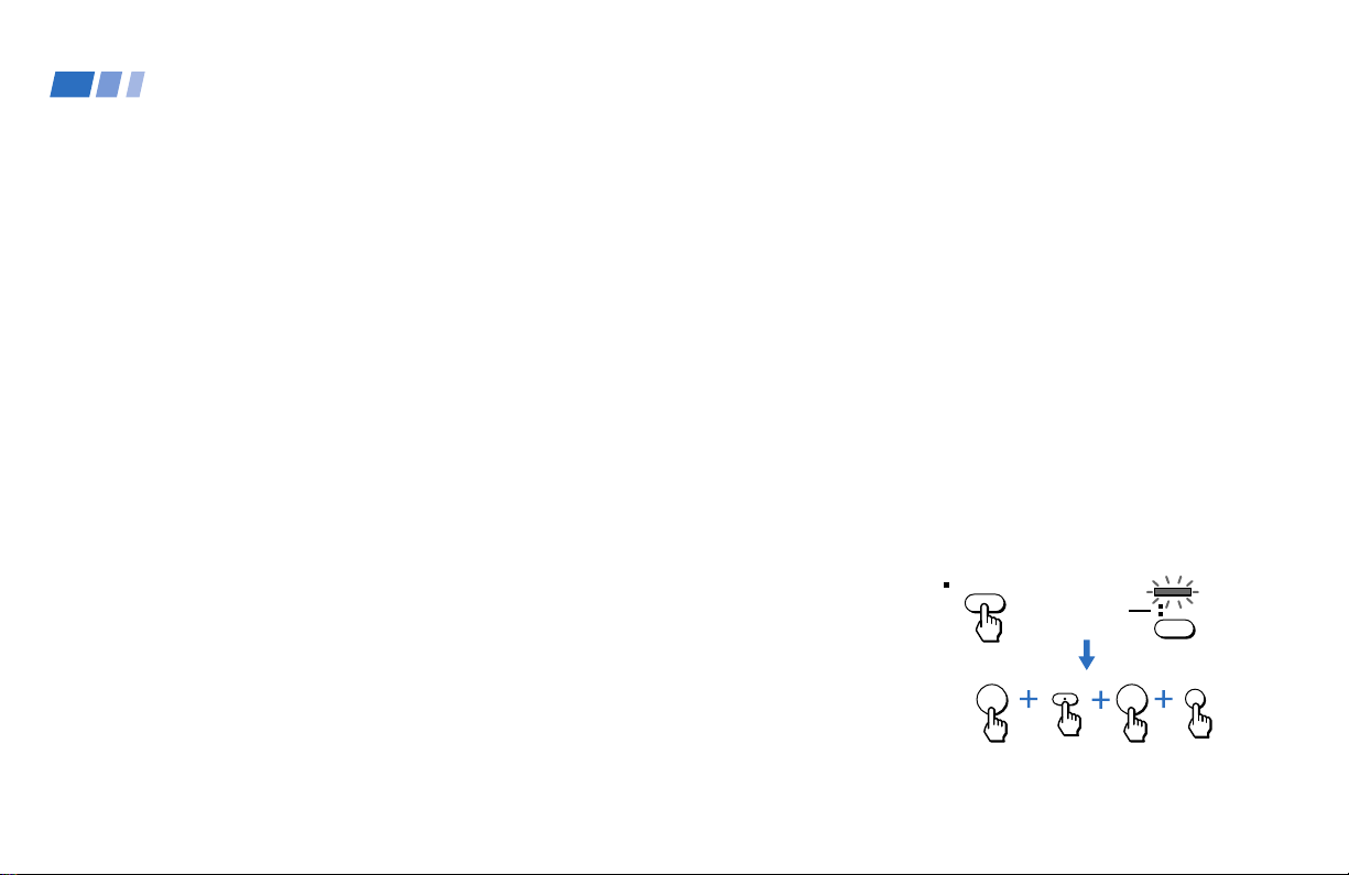
How can I select digital channels?
Digital channels are indicated by the use of a
decimal or “dot” in the subchannel number (for
example, “2.1”). This number appears when
you press the CH +/– buttons or press the
DISPLAY button.
Before selecting a digital channel, press DTV
ANT on the remote control so that the TV
FUNCTION indicator on the remote control
lights up in green. To select a subchannel
directly, use the 0–9 buttons, • (dot) button,
and the ENTER button.
For example, to select subchannel 2.1
You can also select digital channels using an on-
screen guide. See page 31 for details.
DTV ANT
TVFUNCTION
Lights up in
green.
2
ENTER
1

4
Safety
• Operate the projection TV only on 120 V
AC.
• The plug is designed, for safety purposes,
to fit into the wall outlet only one way. If
you are unable to insert the plug fully into
the outlet, contact your dealer.
• If any liquid or solid object should fall
inside the cabinet, unplug the projection
TV immediately and have it checked by
qualified service personnel before
operating it further.
• If you will not be using the projection TV
for several days, disconnect the power by
pulling the plug itself. Never pull on the
cord.
For details concerning safety precautions, see the
supplied leaflet “IMPORTANT SAFEGUARDS.”
Note on cleaning
Clean the cabinet of the projection TV with a
dry soft cloth. To remove dust from the
screen, wipe it gently with a soft cloth.
Stubborn stains may be removed with a cloth
slightly dampened with solution of mild soap
and warm water. Never use strong solvents
such as thinner or benzine for cleaning.
Precautions
If the picture becomes dark after using the
projection TV for a long period of time, it may
be necessary to clean the inside of the
projection TV. Consult qualified service
personnel.
Installing
• To prevent internal heat buildup, do not
block the ventilation openings.
• Do not install the projection TV in a hot or
humid place, or in a place subject to
excessive dust or mechanical vibration.
• Avoid operating the projection TV at
temperature below 5°C (41°F).
• The DTV I/O cable has already been
attached between the projection TV’s
lower panel and the DTV I/O connector
on the projection TV’s upper panel. Never
touch, tamper with, or disconnect the
DTV I/O cable from the connector, as this
may cause damage to the projection TV.
• If the projection TV is transported directly
from a cold to a warm location, or if the
room temperature changes suddenly, the
picture may be blurred or show poor
color. In this case, please wait a few hours
to let the moisture evaporate before
turning on the projection TV.
• To obtain the best picture, do not expose
the screen to direct illumination or direct
sunlight. It is recommended to use spot
lighting directed down from the ceiling or
to cover the windows that face the screen
with opaque drapery. It is desirable to
install the projection TV in a room where
the floor and walls are not of a reflective
material.
5
Installing and Connecting the Projection TV
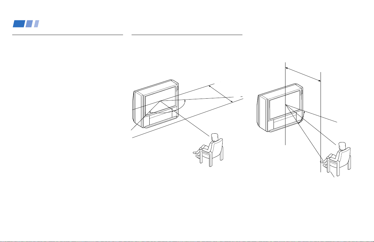
Recommended viewing area
(Vertical)
Carrying Your Projection TV
Carrying the projection TV requires four or
more people.
The projection TV has been equipped with
casters for easy movement on a hard surface.
Please move your projection TV using the
casters.
Installing the Projection TV
Recommended viewing area
(Horizontal)
60°
60°
60°
min. 2.4m (approx. 8 ft.)
20°
min. 2.4m (approx. 8ft.)
20°
6
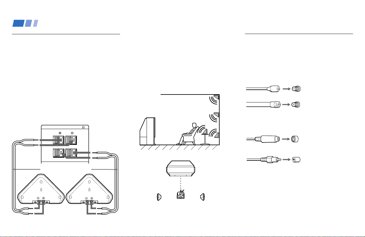
L
R
REAR SPEAKER OUT
(
MIN 16
)
Mounting the Supplied Rear
Speakers
For enhanced surround effect, connect the
supplied rear speakers to your projection TV.
Connecting the rear speakers
Using the supplied speaker cords, connect
REAR SPEAKER OUT L on your projection
TV to the speaker terminal on one rear
speaker, and connect REAR SPEAKER OUT
R to the terminal on the other one.
Note:
• Match the colors of the speaker cords and
the terminals. If the colors are reversed,
sound will be distorted.
(Rear of projection TV)
Speaker cord (supplied)
Speaker (supplied)
Speaker (supplied)
(Rear of projection TV)
Projection TV
Rear speaker
Left rear
speaker
Right rear
speaker
Installation
For optimum surround effect, mount the rear
speakers in the following places (as shown in
the illustration):
• on a wall, a little higher or lower than the
listener’s ears.
• on a table, a little lower than the listener’s
ears.
• at the corner where the wall and ceiling
meet.
Installing and Connecting the Projection TV (continued)
Connector Types
You may find it necessary to use some of the
following connector types during set up.
Coaxial cable
Standard TV cable and antenna cable
S Video cable
High quality video cable for enhanced
picture quality
Audio/Video cable
Video - Yellow
Audio (Left) - White
Audio (Right) - Red
Some DVD Players are equipped with the
following three video connectors.
Y - Green
P
B (CB, Cb or B–Y) - Blue
P
R (CR, Cr or R–Y) - Red
Plug Type
Screw-on Type
Screw into connection.
Push into connection.
Align guides and
push into connection.
Push into connection.
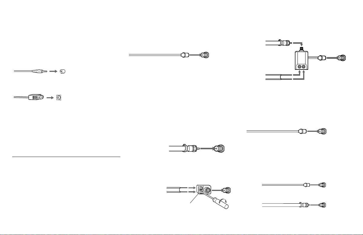
7
S-Link/CONTROL S cable
Sony cable for S-Link and CONTROL S
connections. These features are exclusive to
Sony products and allow greater control of
all Sony equipment.
Optical digital cable
Note:
• For S-Link and CONTROL S connections,
you can use the combined S-Link/
CONTROL S cable provided with some
Sony video equipment, or you can purchase
a separate S-Link/CONTROL S cable (RK-
G69HG).
Making Connections
To receive DTV channels
First, install a roof antenna and connect it to
the VHF/UHF (DTV) connector on the lower
panel at the rear of the projection TV. Second,
connect another antenna or cable line to the
VHF/UHF connector on the upper panel at
the rear of the projection TV.
Connecting directly to a cable or
an antenna
The connection you choose will depend on
the cable found in your home. Newer homes
will be equipped with standard coaxial cable
(see
A); older homes will probably have 300-
ohm twin lead cable (see
B); still other homes
may contain both (see C).
A
• VHF only
or
• VHF/UHF
or
• Cable
B
• VHF only
or
• UHF only
or
• VHF/UHF
Antenna connector
(Rear of
projection TV)
VHF/UHF
300-ohm twin
lead cable
75-ohm
coaxial cable
75-ohm coaxial cable
Push into connection.
EAC-66 U/V mixer
(not supplied)
300-ohm twin lead cable
(Rear of
projection TV)
VHF/UHF
(Rear of
projection TV)
VHF/UHF
Push into connection.
C
• VHF
and
• UHF
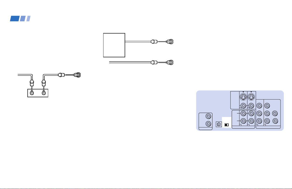
Cable or antenna
This is the simplest connection. Connection is
made directly from the cable or antenna to
the projection TV.
Cable and antenna
You may find it convenient to use the
following set up if your cable provider does
not feature local channels that you are able to
receive using an antenna.
(Rear of projection TV)
VHF/UHF
Coaxial cable
(Rear of
projection TV)
AUX
VHF/UHF
CATV cable
Antenna cable
(continued)
(Rear of projection TV)
VHF/UHF
(DTV)
Roof antenna
8
For this set up, you can switch between
scrambled channels (through your cable
box), and normal (CATV) channels by
pressing TV ANT on your remote control.
Notes:
• You may be able to program your Sony
remote control to operate your cable box.
(see “Operating a Cable Box or DBS
Receiver” on page 74)
• During PIP, P&P, CHANNEL INDEX or
FAVORITE CHANNEL viewing, the
AUX input can only be viewed in the
main picture.
• If you are connecting a cable box through
the AUX input and would like to switch
between the AUX and normal (CATV)
input, you should consider using
CHANNEL FIX.
(see “CHANNEL FIX” on page 56)
*Cable box
Cable
OUTIN
(Rear of projection TV)
VHF/UHF
Select Cable or ANT mode by pressing TV
ANT on the remote control.
Connecting a cable box
Some pay cable TV systems use scrambled or
encoded signals that require a cable box* to
view all channels.
Note:
• If you will be controlling all channel
selection through your cable box, you
should consider using the CHANNEL
FIX feature. (see “CHANNEL FIX” on
page 56)
Cable box and cable
Some pay cable TV systems use scrambled or
encoded signals requiring a cable box* only for
certain channels (e.g. HBO, SHOWTIME, etc.)
*Cable box
VHF/UHF
(Rear of projection TV)
AUX
CATV cable
(unscrambled channels)
About the DOWN CONVERTER
switch
The DOWN CONVERTER switch on the
projection TV’s lower panel must be set to
OFF to receive an HD signal. Do not change
the switch position.
Note:
• If the DOWN CONVERTER switch is set
to ON, set the switch to OFF and turn off
the projection TV. Then, turn the power
back on to activate the new switch
position (OFF).
About the DTV I/O cable
The DTV I/O cable has already been
attached between the projection TV’s lower
panel and the DTV I/O connector on the
projection TV’s upper panel. Never touch,
tamper with, or disconnect the DTV I/O
cable from the connector, as this may cause
damage to the projection TV.
Installing and Connecting the Projection TV (continued)
S VIDEO
VIDEO
VIDEO OUT
3
Y
P
B
P
R
R
G
B
HD
VD
AUDIO OUT
L
(MONO)
DOWN
CONVERTER
1
2
4
1
2
OFF
ON
DOLBY DIGITAL
OUTPUT
(OPTICALL)
R
CONTROL S
OUT
IN
9
CONTROL SCONTROL S
DOLBY DIGITAL
OUT
(OPTICALL)
IN
OUT
SD/HD
S VIDEO
S-LINK/
CONTROL S
OUT
S-LINK/
CONTROL S
IN
VIDEO
AUDIO
L
R
R
VIDEO
L
AUDIO
VHF/UHF
AUX
(MONO)
IN OUT
VIDEO 1 VIDEO 3 VIDEO 4 (DVD) SELECT
VHF/UHF
(DTV)
Y
P
B
PR
LINE
OUT
OUT
IN
AUDIO R AUDIO L VIDEO
S VIDEO
VHF/UHF
LINE
IN
S VIDEO
VIDEO
VIDEO OUT
3
Y
P
B
P
R
R
G
B
HD
VD
AUDIO OUT
L
(MONO)
R
1
2
4
1
2
Disconnect all power sources before making any connections.
Connecting an antenna/cable TV
system to a VCR
1 Attach the coaxial cable from the roof
antenna to VHF/UHF (DTV) on the TV’s
lower panel.
2 Attach the coaxial cable from the
incoming cable connection or antenna to
IN on the VCR.
3 Using a coaxial cable, connect OUT on the
VCR to VHF/UHF on the TV’s upper
panel.
4 Using AUDIO and S VIDEO* cables,
connect AUDIO and S VIDEO OUT on the
VCR to AUDIO and S VIDEO IN on the
TV’s upper panel (White-AUDIO Left,
Red-AUDIO Right).
5 Using AUDIO and S VIDEO* cables,
connect AUDIO and S VIDEO IN on the
VCR to AUDIO and S VIDEO OUT on the
TV’s lower panel.
* If your VCR is not equipped with S VIDEO, use a
VIDEO cable (yellow) instead of the S VIDEO
cable.
Note:
• If you are connecting a monaural VCR,
connect only the single audio output to
the left (MONO) input on the projection
TV.
1
VMC-810S/820S (not supplied)
YC-15V/30V (not supplied)
VCR
2
Cable/
Antenna
4
3
Coaxial cable
YC-15V/30V
(not supplied)
S VIDEO
AUDIO R
Roof
antenna
S VIDEO
(Rear of projection TV)
AUDIO-L
AUDIO-R
5
VIDEO
VIDEO
AUDIO L
VMC-810S/820S
(not supplied)
10
CONTROL SCONTROL S
DOLBY DIGITAL
OUT
(OPTICALL)
IN
OUT
SD/HD
S VIDEO
S-LINK/
CONTROL S
OUT
S-LINK/
CONTROL S
IN
VIDEO
AUDIO
L
R
R
VIDEO
L
AUDIO
VHF/UHF
AUX
(MONO)
IN OUT
VIDEO 1 VIDEO 3 VIDEO 4 (DVD) SELECT
Y
P
B
PR
LINE
OUT
OUT
IN
AUDIO R AUDIO L VIDEO
S VIDEO
VHF/UHF
LINE
IN
OUT
IN
VHF/UHF
(DTV)
S VIDEO
VIDEO
VIDEO OUT
3
Y
P
B
PR
R
G
B
HD
VD
AUDIO OUT
L
(MONO)
R
1
2
4
1
2
Installing and Connecting the Projection TV (continued)
Connecting a VCR and projection
TV to a cable box
1 Attach the coaxial cable from the roof
antenna to VHF/UHF (DTV) on the TV’s
lower panel.
2 Connect the single (input) jack of the
splitter to the incoming cable connection,
and connect the other two (output) jacks
(using the coaxial cable) to IN on the cable
box and VHF/UHF on the TV’s upper
panel.
3 Using a coaxial cable, connect OUT on the
cable box to IN on the VCR.
4 Using AUDIO and S VIDEO* cables,
connect AUDIO and S VIDEO OUT on the
VCR to AUDIO and S VIDEO IN on the
TV’s upper panel (White-AUDIO Left,
Red-AUDIO Right).
5 Using AUDIO and S VIDEO* cables,
connect AUDIO and S VIDEO IN on the
VCR to AUDIO and S VIDEO OUT on the
TV’s lower panel.
* If your VCR is not equipped with S VIDEO, use a
VIDEO cable (yellow) instead of the S VIDEO
cable.
Note:
• To view scrambled channels through the
cable box, select the video input which the
cable box is connected to by pressing TV/
VIDEO.
Coaxial cable
AUDIO-R
Cable/
Antenna
VCR
1
2
YC-15V/30V (not supplied)
4
3
Cable box
Splitter
(not supplied)
YC-15V/30V
(not supplied)
Roof
antenna
2
S VIDEO
AUDIO-L
S VIDEO
AUDIO-L
AUDIO-R
(Rear of projection TV)
5
VIDEO
VIDEO
VMC-810S/820S (not supplied)
VMC-810S/820S
(not supplied)
Disconnect all power sources before making
any connections.
11
S VIDEO
S-LINK/
CONTROL S
OUT
S-LINK/
CONTROL S
IN
VIDEO
AUDIO
L
R
VIDEO
(MONO)
IN OUT
VIDEO 1 VIDEO 3 VIDEO 4 (DVD) SELECT
Y
P
B
PR
R
L
AUDIO
VHF/UHF
AUX
VHF/UHF
S VIDEO
OUT
IN
LINE OUT
SATELLITE IN
AUDIO R AUDIO L VIDEO
(DTV)
VHF/UHF
Disconnect all power sources before making any connections.
S VIDEO
AUDIO-L
AUDIO-R
Cable/
Antenna
(Rear of projection TV)
1
2
RK-74A (not supplied)
3
Satellite antenna
cable
DBS
YC-15V/30V (not supplied)
4
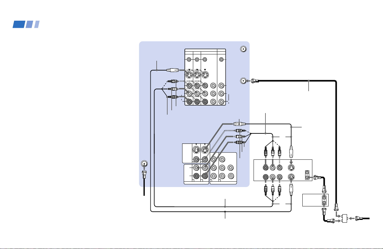
Connecting a DBS (Direct
Broadcast Satellite) receiver
1 Attach the coaxial cable from the roof
antenna to VHF/UHF (DTV) on the TV’s
lower panel.
2 Connect the cable from the satellite
antenna to the DBS receiver.
3 Attach the coaxial cable from the incoming
cable connection or antenna to VHF/UHF
on the TV’s upper panel.
4 Using AUDIO and S VIDEO cables,
connect AUDIO and S VIDEO OUT on the
DBS receiver to AUDIO and S VIDEO IN
on the TV’s upper panel (White-AUDIO
Left, Red-AUDIO Right).
Note:
• To view input from the DBS, select the
video input which the DBS receiver is
connected to by pressing TV/VIDEO on
the remote control.
Roof
antenna
12
CONTROL S
DOLBY DIGITAL
OUT
(OPTICALL)
IN
OUT
SD/HD
S VIDEO
S-LINK/
CONTROL S
OUT
S-LINK/
CONTROL S
IN
VIDEO
AUDIO
L
R
R
VIDEO
L
AUDIO
VHF/UHF
AUX
(MONO)
IN OUT
VIDEO 1 VIDEO 3 VIDEO 4 (DVD) SELECT
Y
P
B
P
R
LINE
OUT
OUT
IN
AUDIO R AUDIO L VIDEO
S VIDEO
VHF/UHF
LINE
IN
LINE
OUT
OUT
IN
VHF/UHF
SATELLITE IN
S VIDEO
VIDEO
VIDEO OUT
3
Y
P
B
P
R
R
G
B
HD
VD
AUDIO OUT
L
(MONO)
R
1
2
4
1
2
VHF/UHF
(DTV)
Installing and Connecting the Projection TV (continued)
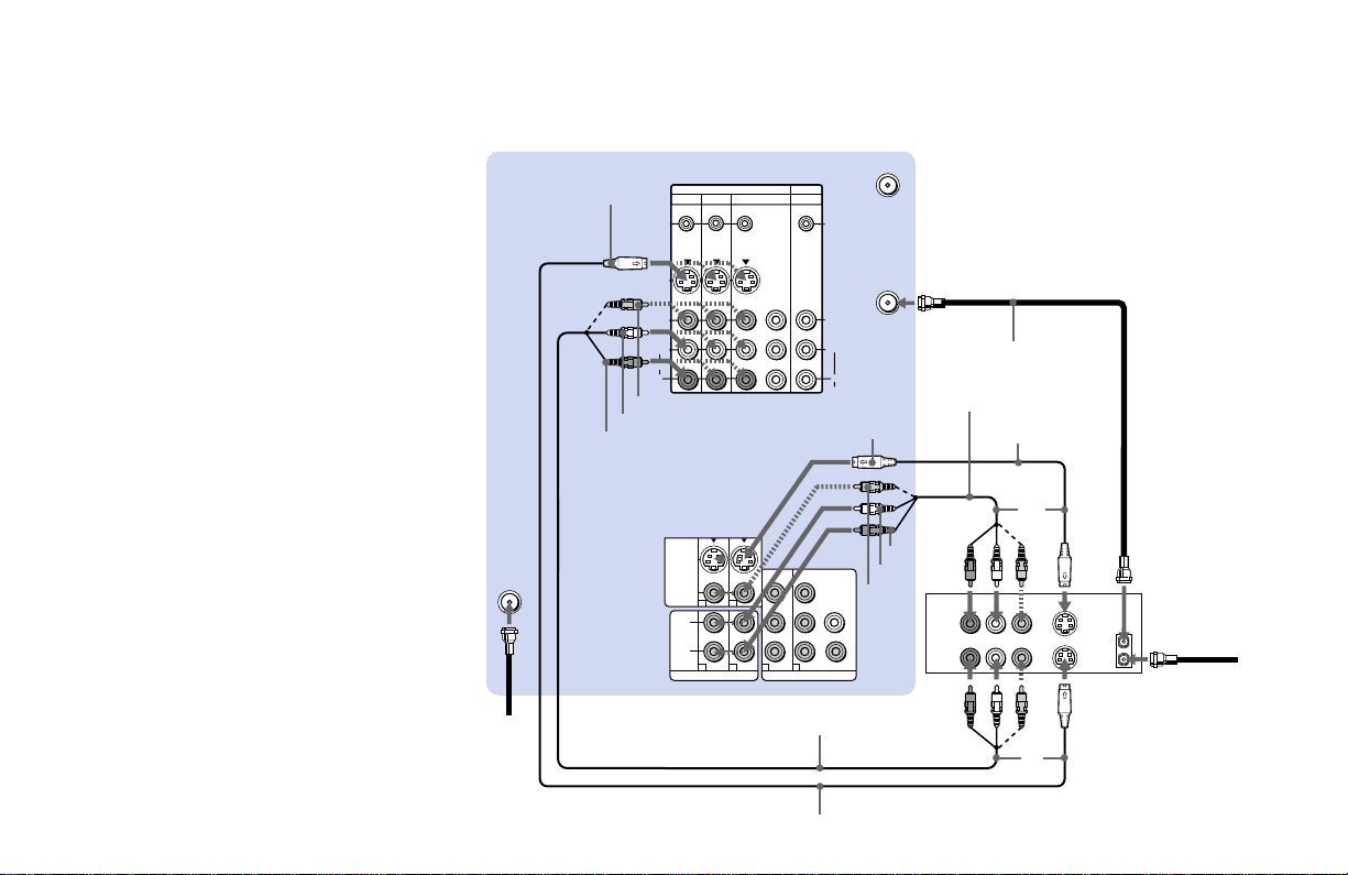
Connecting a DBS (Direct Broadcast
Satellite) receiver and a VCR
1-3 Perform as described on page 9.
4 Connect the cable from the satellite antenna
to the DBS receiver.
5 Using AUDIO and S VIDEO cables, connect
AUDIO and S VIDEO OUT on the DBS
receiver to AUDIO and S VIDEO IN of
VIDEO 4 IN on the TV’s upper panel
(White-AUDIO Left, Red-AUDIO Right).
6 Using AUDIO and S VIDEO* cables,
connect AUDIO and S VIDEO OUT on the
VCR to AUDIO and S VIDEO IN of VIDEO
1 IN on the TV’s upper panel.
7 Using AUDIO and VIDEO cables, connect
AUDIO and VIDEO IN on the VCR to
AUDIO and VIDEO OUT of SELECT OUT
on the TV’s upper panel.
8 Using AUDIO and S VIDEO* cables,
connect AUDIO and S VIDEO OUT of
VIDEO 2 OUT on the TV’s lower panel to
AUDIO and S VIDEO IN of VIDEO 3 IN on
the TV’s upper panel.
9 To record a DTV program on the VCR, use
the SET UP menu to set SELECT OUT to
“VIDEO3.” Set it to “VIDEO4” to record a
DBS program.
Disconnect all power sources before making any connections.
AUDIO-L
AUDIO-R
S VIDEO
RK-74A
(not supplied)
3
Satellite
antenna
cable
DBS
VCR
6
YC-15V/30V
(not supplied)
5
1
Roof
antenna
RK-74A
(not
supplied)
YC-15V/30V (not supplied)
RK-74A
(not
supplied)
YC-15V/30V
(not
supplied)
7
VMC-810S/820S
(not supplied)
S VIDEO
AUDIO-L
AUDIO-R
S VIDEO
8
4
AUDIO-L
AUDIO-R
S VIDEO
AUDIO-L
AUDIO-R
Cable/
Antenna
AUDIO-R
AUDIO-L
VIDEO
(Rear of projection TV)
2
Coaxial cable
13
PUSH
S VIDEO
VIDEO
L(MONO)
R
AUDIO
VIDEO 2
* If your VCR is not equipped with S VIDEO, use a
VIDEO cable (yellow) instead of the S VIDEO
cable.
Note:
• To view input from the DBS or VCR,
select the video input which your DBS
receiver or VCR is connected to by
pressing TV/VIDEO on the remote
control.
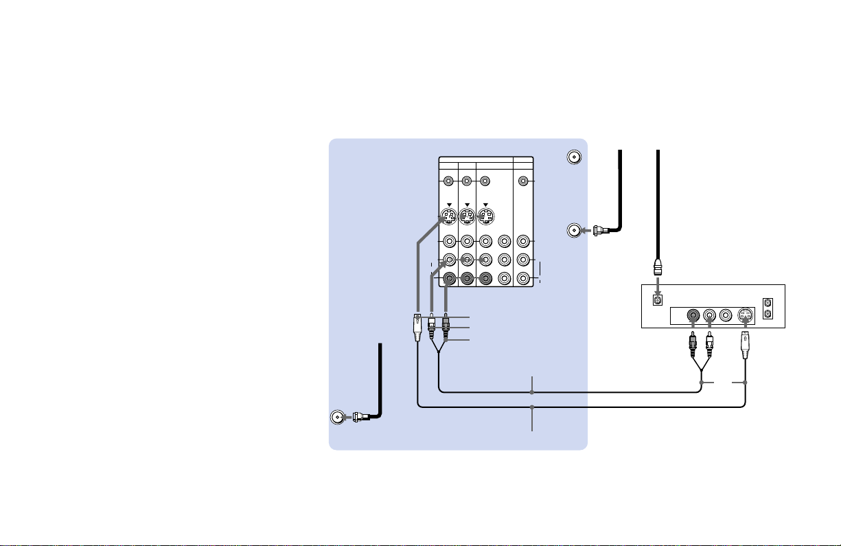
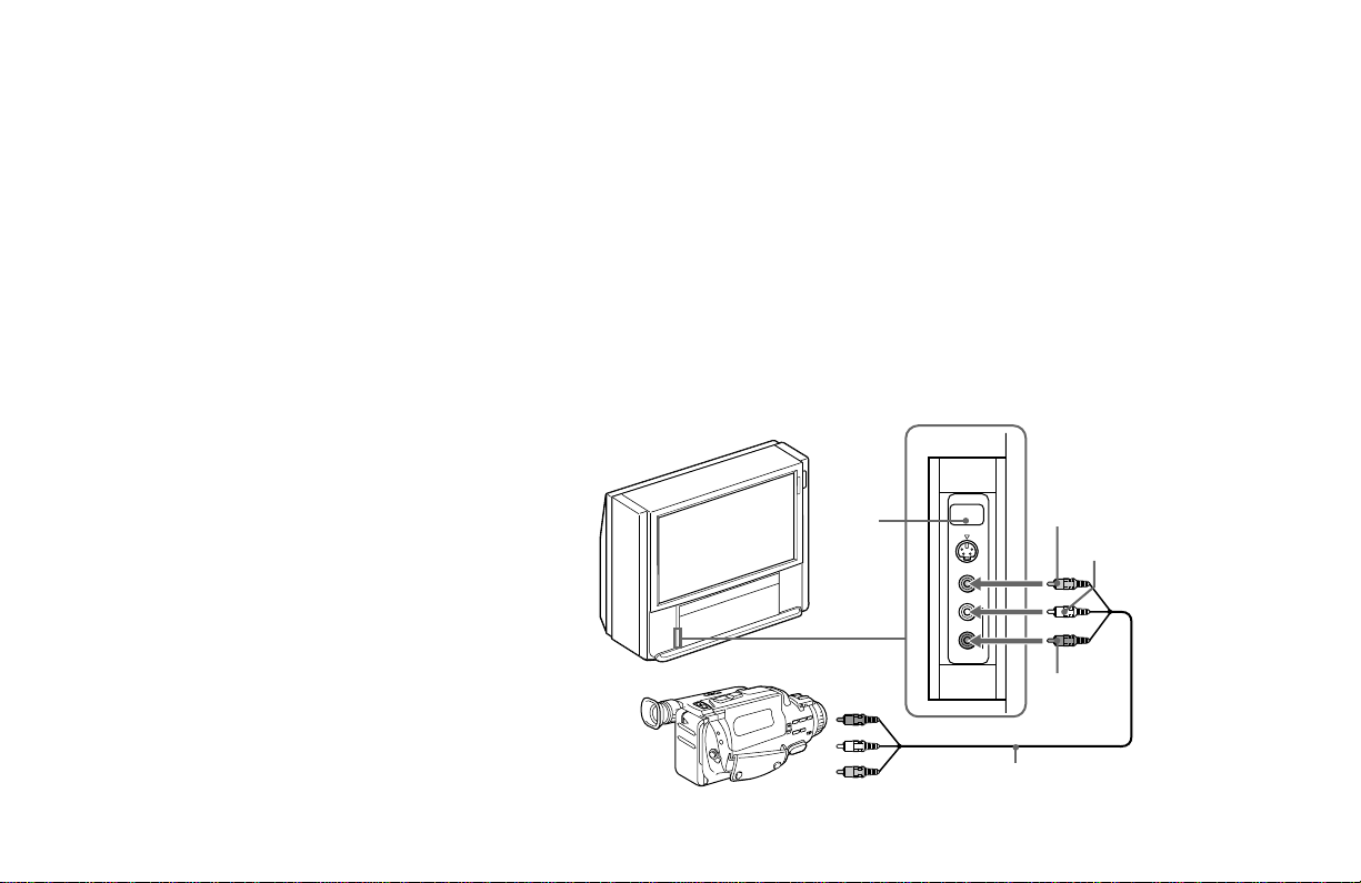
Connecting a camcorder
Use this connection to view a picture directly
from your camcorder.
1 Using an AUDIO/VIDEO cable, connect
AUDIO and VIDEO OUT on the
camcorder to AUDIO and VIDEO IN on
the lower left side on the front of the
projection TV (Yellow-VIDEO, White-
AUDIO Left, Red-AUDIO Right).
2 Press VIDEO 2 to select the video inputs
from a camcorder.
Notes:
• If you are connecting a monaural
camcorder, connect only the single audio
output to the left (MONO) input on the
projection TV.
• If you have an S Video equipped
camcorder, you can use an S Video
connection.
Disconnect all power sources before making any connections.
(Front of projection TV)
VIDEO
Audio/video
outputs
Camcorder
VMC-810S/820S
(not supplied)
AUDIO-L
AUDIO-R
2
1

14
S VIDEO
S-LINK/
CONTROL S
OUT
S-LINK/
CONTROL S
IN
VIDEO
AUDIO
L
R
R
VIDEO
L
(MONO)
IN OUT
VIDEO 1 VIDEO 3 VIDEO 4 (DVD) SELECT
Y
P
B
P
R
AUDIO R AUDIO L VIDEO
LINE
OUT
OUT
IN
AUDIO R AUDIO L VIDEO
LINE
IN
OUT
IN
AUDIO
VHF/UHF
AUX
Disconnect all power sources before making any connections.
(Rear of projectionTV)
Indicates direction
of signal
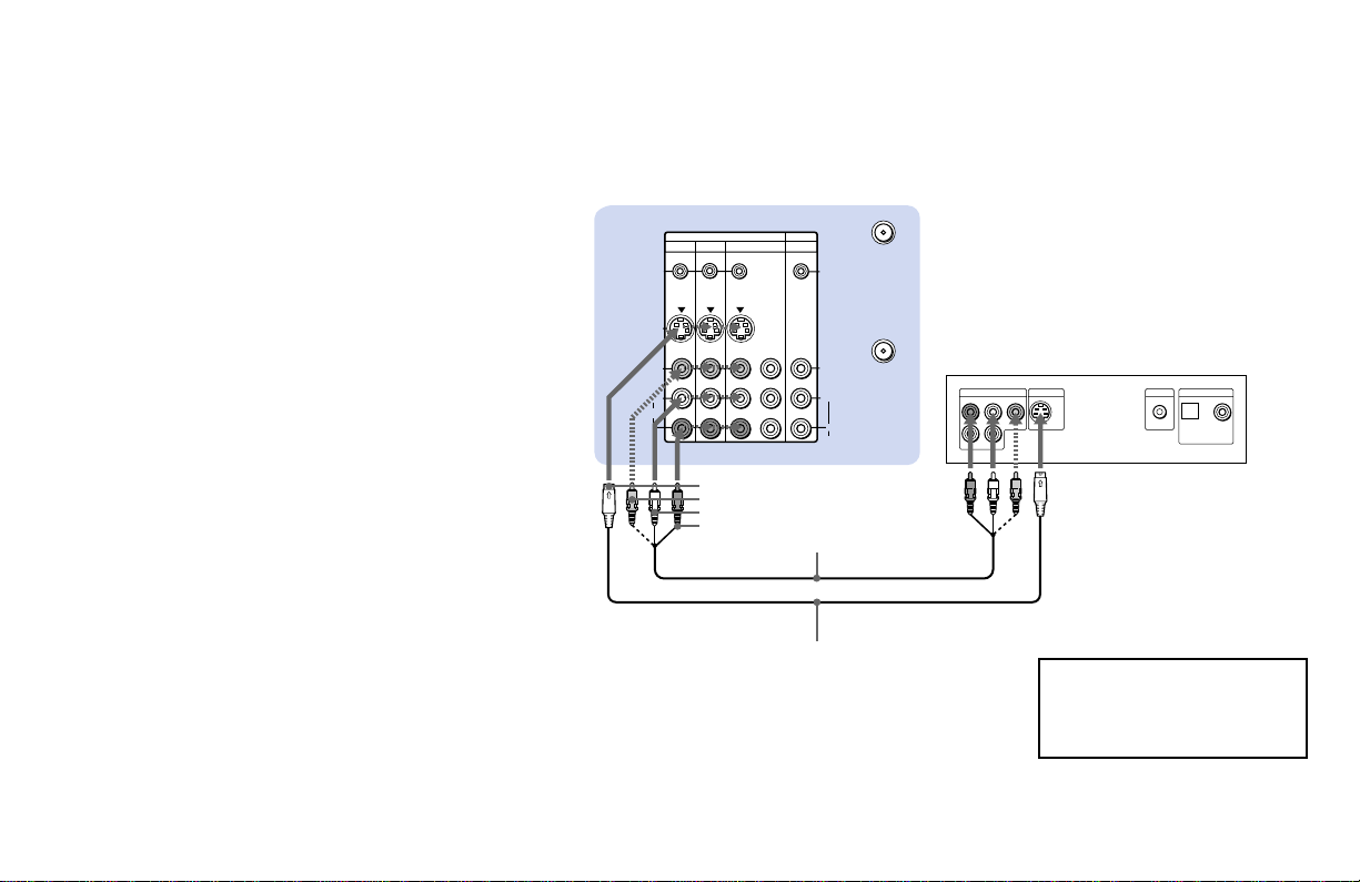
Connecting two VCRs for tape
editing
SELECT OUT gives you the ability to use a
second VCR to record a program being
played by the primary VCR or to perform
tape editing and dubbing.
1 Connect the VCR intended for playback
using the connection instructions on page
9 of this manual.
2 Using an AUDIO/VIDEO cable, connect
AUDIO and VIDEO IN on the VCR
intended for recording to AUDIO and
VIDEO OUT of SELECT OUT on the TV’s
upper panel.
Notes:
• Do not change the input signal while
editing through SELECT OUT.
• When connecting a single VCR to the
projection TV: if VCR LINE OUT is
connected to VIDEO IN on the TV’s
upper panel, do not connect the SELECT
OUT on the TV’s upper panel to the VCR
LINE INPUT (see right). Doing so will
cause program interference and other
viewing problems.
• You can select the output signal from
SELECT OUT from the SET UP menu.
(see “SELECT OUT” on page 60)
VIDEO
AUDIO-L
AUDIO-R
(Rear of projection TV)
VCR (for recording)
1
2
VMC-810S/820S
(not supplied)
VCR
(for playback)
VMC-810S/820S (not supplied)
LINE
OUT
IN
SELECT
OUT
VIDEO IN
VCR
Installing and Connecting the Projection TV (continued)
VIDEO
AUDIO-L
AUDIO-R
15
LINE OUT
S VIDEO OUT
S-LINK
DIGITAL OUT
R–AUDIO 1–L VIDEO
OPTICAL COAXIAL
S VIDEO
S-LINK/
CONTROL S
OUT
S-LINK/
CONTROL S
IN
VIDEO
AUDIO
L
R
VIDEO
(MONO)
IN OUT
VIDEO 1 VIDEO 3 VIDEO 4 (DVD) SELECT
Y
P
B
P
R
R
L
AUDIO
VHF/UHF
AUX
Disconnect all power sources before making any connections.
Connecting a DVD Player without
component video output
connectors
Using an AUDIO and S VIDEO* cables,
connect AUDIO and S VIDEO IN on the TV’s
upper panel to LINE OUT on the DVD
Player (White-AUDIO Left, Red-AUDIO
Right).
* If your DVD Player is not equipped with S
VIDEO, use a VIDEO cable (yellow) instead of
the S VIDEO cable.
Note:
• Since the high quality pictures on a DVD
disc contain a lot of information, picture
noise may appear. In this case, adjust NR
in the VIDEO menu. (see “NR” on page
48)
Connect the DVD Player directly to
the projection TV. Connecting the
DVD Player through other video
equipment will cause unwanted
picture noise.
AUDIO-R
DVD
VMC-810S/820S
(not supplied)
(Rear of projection TV)
Audio/video outputs
AUDIO-L
S video output
YC-15V/30V (not supplied)
S VIDEO
VIDEO

16
LINE OUT
S VIDEO OUT
S-LINK
DIGITAL OUT
R–AUDIO 1–L VIDEO
OPTICAL COAXIAL
R-YY B-Y
COMPONENT VIDEO OUT
S VIDEO
S-LINK/
CONTROL S
OUT
S-LINK/
CONTROL S
IN
VIDEO
AUDIO
L
R
VIDEO
(MONO)
IN OUT
VIDEO 1 VIDEO 3 VIDEO 4 (DVD) SELECT
Y
P
B
PR
R
L
AUDIO
VHF/UHF
AUX
Disconnect all power sources before making any connections.
Connecting a DVD Player with
component video output
connectors
1 Using an AUDIO cable, connect AUDIO R
and L of LINE OUT on the DVD Player to
AUDIO R and L of VIDEO 4 IN on the TV’s
upper panel (White-AUDIO Left, Red
AUDIO Right).
2 Using three yellow VIDEO cables,
connect Y, P
B, and PR of the
COMPONENT VIDEO OUT on the DVD
Player to Y, P
B, and PR of VIDEO 4 IN on
the TV’s upper panel.
Notes:
• Some DVD Player terminals may be
labeled differently. If so, connect as
follows:
Connect To
Y (green) Y
PB (blue) CB, Cb or B-Y
PR (red) CR, Cr or R-Y
• Since the high quality pictures on a DVD
disc contain a lot of information, picture
noise may appear. In this case, adjust NR
in the VIDEO menu. (see “NR” on page
48)
Connect the DVD Player directly
to the projection TV. Connecting
the DVD Player through other
video equipment will cause
unwanted picture noise.
AUDIO-L
AUDIO-R
RK-74A (not supplied)
DVD
VMC-10HG (not supplied)
(Rear of projection TV)
1
2
Installing and Connecting the Projection TV (continued)
17
S VIDEO
S-LINK/
CONTROL S
OUT
S-LINK/
CONTROL S
IN
VIDEO
AUDIO
L
R
R
VIDEO
L
(MONO)
IN OUT
VIDEO 1 VIDEO 3 VIDEO 4 (DVD) SELECT
Y
P
B
P
R
LINE
OUT
OUT
IN
LINE
IN
VHF/UHF
AUDIO
VHF/UHF
AUX
VHF/UHF
(DTV)
Disconnect all power sources before making any connections.
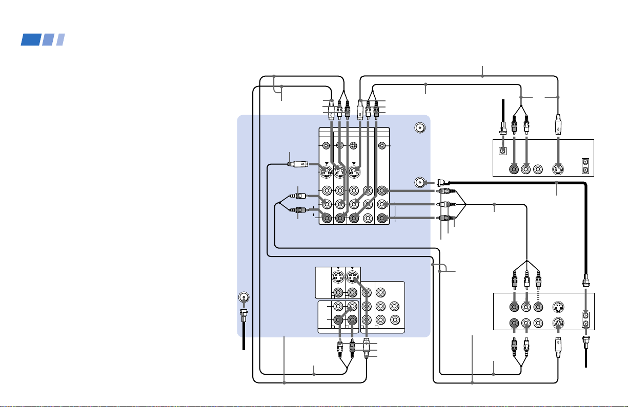
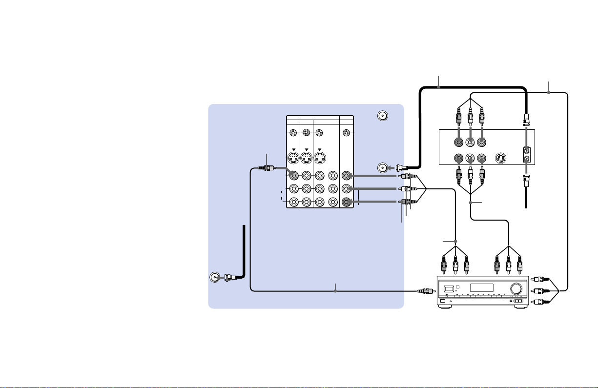
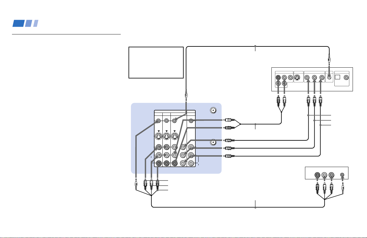
Connecting an AV receiver
For greater control of all audio and video
equipment, connect an AV receiver.
1-3 Perform as described on page 9.
4 Using a VIDEO cable, connect VIDEO 1 IN
on the TV’s upper panel to MONITOR
OUT on the AV receiver.
5 Using an AUDIO/VIDEO cable, connect
SELECT OUT on the TV’s upper panel to
VIDEO 2 IN on the AV receiver.
6 Using an AUDIO/VIDEO cable, connect
the video equipment to the AV receiver.
7 Use the SET UP menu to set SELECT OUT to
TV OUT. (see “SELECT OUT” on page 60)
Note:
• You may want to use CHANNEL FIX to
fix your TV’s input to the AV receiver
(VIDEO 1). (see “CHANNEL FIX” on
page 56)
AUDIO-R
AUDIO/
VIDEO 1
OUT
AV receiver
VMC-810S/
820S (not
supplied)
2
1
Roof
Antenna
MONITOR
OUT
AUDIO/
VIDEO 1 IN
VMC-810S/820S (not supplied)
3
VMC-810S/
820S (not
supplied)
AUDIO/
VIDEO
2 IN
4
VCR
5
6
VIDEO
VIDEO
Coaxial cable
6
(Rear of projection TV)
VMC-10HG
Cable/
Antenna
AUDIO-L
18
HRD
R
L
AUDIO OUT
VAR FIX
L
R
Connecting an audio system
For more dynamic sound, connect an audio
system to the projection TV.
1 Using an AUDIO cable, connect AUDIO
(VAR) OUT on the TV’s upper panel to
one of the unused Line inputs (e.g. Tape-
2, AUX1, etc.) on the stereo (White-
AUDIO Left, Red-AUDIO Right).
2 Set the stereo to the chosen Line input
and use the AUDIO menu to switch the
TV’s speakers off. (see “SPEAKER” on
page 49)
Note:
• You can adjust VOLUME, BASS, TREBLE
and BALANCE through the projection
TV on AUDIO (VAR) OUT only.
Disconnect all power sources before making any connections.
(Rear of projection TV)
AUDIO (VAR)
OUT-R
RK-74A
(not supplied)
Line input
AUDIO (VAR) OUT-L
1
2
Stereo amplifier
Installing and Connecting the Projection TV (continued)
19
R
L
AUDIO OUT
VAR
FIX
L
R
S VIDEO
VIDEO
VIDEO OUT
3
Y
P
B
P
R
R
G
B
HD
VD
AUDIO OUT
L
(MONO)
1
2
4
1
2
DOLBY DIGITAL
OUTPUT
(OPTICAL)
R
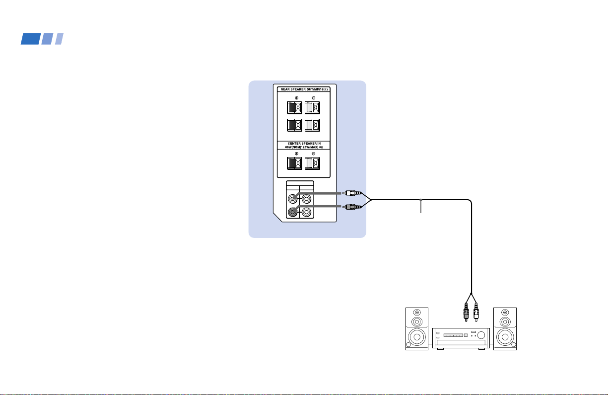
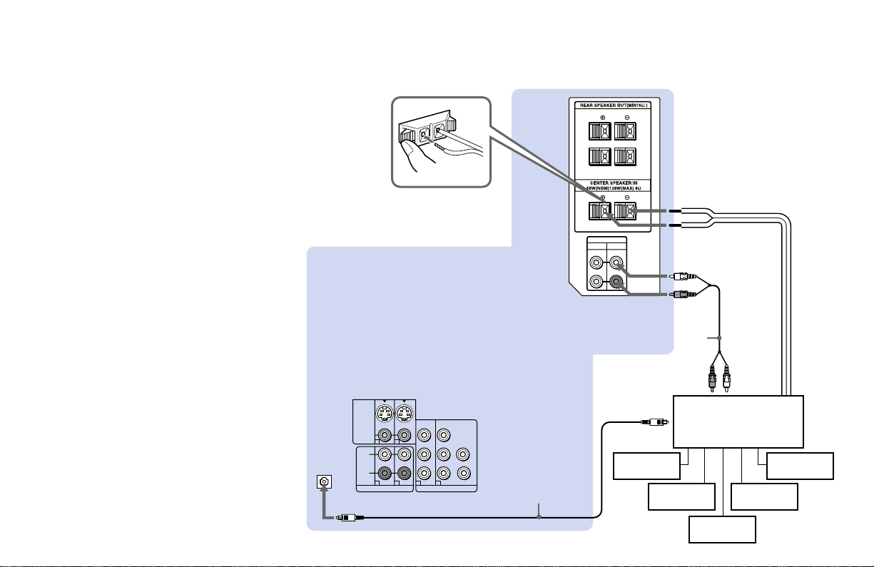
Connecting an amplifier that
supports Dolby Pro Logic/Dolby
Digital decoder
If you use an amplifier with a Dolby Pro
Logic/Dolby Digital decoder instead of the
projection TV’s audio system, you can still
use the projection TV’s center speaker.
1 Using the speaker cords (supplied with
the amplifier), connect the speaker
terminals on the amplifier to CENTER
SPEAKER IN +/– on the TV’s upper
panel.
2 Using an AUDIO cable, connect AUDIO
(FIX) OUT on the TV’s upper panel to one
of the unused Line inputs (e.g. Tape-2,
AUX1, etc.) on the amplifier (White-
AUDIO Left, red-AUDIO Right).
3 If the amplifier is equipped with a digital
audio input, connect DOLBY DIGITAL
OUTPUT (OPTICAL) on the TV’s lower
panel to the digital audio input on the
amplifier using the optical digital cable.
4 Set the amplifier to the chosen Line input
and use the AUDIO menu to set
“SPEAKER” to “CENTER IN” on the
projection TV. (see “SPEAKER” on page
49)
Note:
• The Dolby Pro Logic/Dolby Digital
decoder’s digital audio input jacks are
sometimes labeled AC-3 or DCN.
Disconnect all power sources before making any connections.
(Rear of projection TV)
AUDIO (FIX) OUT-R
RK-74A (not supplied)
AUDIO (FIX) OUT-L
Rear
speaker (L)
Front
speaker (L)
Front
speaker (R)
Rear
speaker (R)
CENTER IN ’
CENTER IN ‘
1
2
Line input
Amplifier with Dolby
Pro Logic/Dolby Digital
decoder
Optical digital cable
Woofer
Digital
audio input
4
3
20
LINE OUT
S VIDEO OUT
S-LINK
DIGITAL OUT
R–AUDIO 1–L VIDEO
OPTICAL COAXIAL
P
R
YP
B
COMPONENT VIDEO OUT
AUDIO R AUDIO L VIDEO
LINE
OUT
S-LINK
S VIDEO
S-LINK/
CONTROL S
OUT
S-LINK/
CONTROL S
IN
VIDEO
AUDIO
L
R
R
VIDEO
L
(MONO)
IN OUT
VIDEO 1 VIDEO 3 VIDEO 4 (DVD) SELECT
Y
P
B
P
R
AUDIO
VHF/UHF
AUX
Disconnect all power sources before making any connections.
Using the S-Link/CONTROL S
Function
S-Link is a Sony innovation designed to
make the Sony components work together. It
allows you to automatically switch the
projection TV’s input mode to video when
you press the play button on the Sony S-Link
VCR.
Using the S-Link function without
a Sony AV receiver
1 Connect the Sony VCR (DVD). (see
“Connecting an antenna/cable TV system
to a VCR” on page 9 or “Connecting a
DVD Player with component video
output connectors” on page 16)
2 Using an S-LINK cable, connect the
S-LINK jacks on the VCR (DVD) and the
TV’s upper panel. Ensure that both ends
are seated firmly and that the projection
TV’s S-LINK jack is in the same row as
the AUDIO/VIDEO cable extending from
the Sony VCR (DVD).
Refer also to the Operating
Instructions supplied with
the VCR, DBS tuner, DVD
player, LD player and other
Sony video equipment for
details.
(Rear of projection TV)
VIDEO
AUDIO-L
AUDIO-R
Audio/video/S-LINK cable
Sony DVD
RK-G34, etc. (not supplied)
S-LINK
Audio
outputs
Component
video
outputs
VMC-10HG
(not
supplied)
RK-74A (not supplied)
Sony VCR
Audio/video
outputs
S-LINK
S-LINK
VIDEO4
S-LINK
Installing and Connecting the Projection TV (continued)
21
S VIDEO
S-LINK/
CONTROL S
OUT
S-LINK/
CONTROL S
IN
VIDEO
AUDIO
L
R
R
VIDEO
L
(MONO)
IN OUT
VIDEO 1 VIDEO 3 VIDEO 4 (DVD) SELECT
Y
P
B
P
R
AUDIO R AUDIO L VIDEO
LINE
OUT
AUDIO R AUDIO L VIDEO S-LINK
S-LINK
LINE
OUT
AUDIO
VHF/UHF
AUX
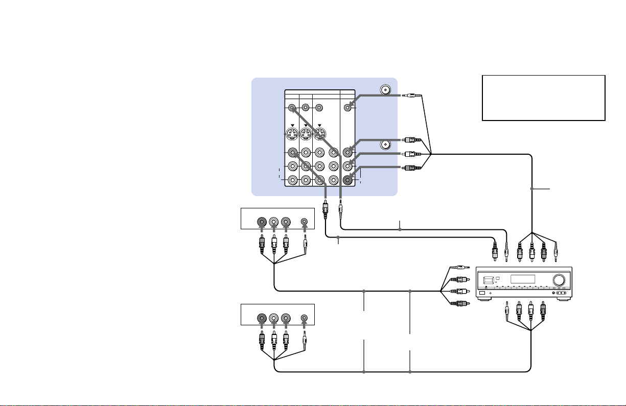
Using the S-Link function with a
Sony AV receiver
1 Using a VIDEO cable, connect VIDEO 1
IN on the TV’s upper panel to MONITOR
OUT on the Sony AV receiver.
2 Using an AUDIO/VIDEO cable, connect
SELECT OUT on the TV’s upper panel to
TV AUDIO and VIDEO IN on the AV
receiver.
3 Using an S-LINK cable, connect S-LINK
on the VIDEO 1 IN panel on the TV’s
upper panel and S-LINK on MONITOR
OUT on the AV receiver.
4 Using an S-LINK cable, connect S-LINK
on the SELECT OUT panel on the TV’s
upper panel to S-LINK on TV IN on the
AV receiver.
5 Using AUDIO/VIDEO and S-LINK
cables, connect the Sony video equipment
to the AV receiver.
6 Use the AUDIO menu to set SPEAKER to
ALL OFF or CENTER IN. (see
“SPEAKER” on page 49)
7 Use the SET UP menu to set SELECT
OUT to TV OUT. (see “SELECT OUT” on
page 60)
8 Press CH (CHANNEL) +/– to activate
the S-Link function.
Disconnect all power sources before making any connections.
Refer also to the Operating
Instructions supplied with the VCR,
DBS tuner, DVD player, LD player
and other Sony video equipment for
details.
(Rear of projection TV)
Audio/video/
S-Link cable
(not supplied)
S-LINK SELECT OUT
Audio/
video
outputs
VCR 1
Audio/
video
outputs
SELECT OUT
RK-G34, etc. (not
supplied)
VIDEO 1 IN VIDEO
S-LINK
VIDEO 1
Video cable
(not supplied)
MONITOR OUT
(video output)
TV IN
(S-LINK and
video/audio
inputs)
VIDEO 1 IN (S-LINK and
video/audio inputs)
Audio/video/
S-Link cable
(not supplied)
VCR 2
VIDEO 2 IN (S-LINK
and video/audio
inputs)
Sony AV receiver
S-LINK
S-LINK
MONITOR OUT
S-LINK
1
2, 4
3
5
22
S VIDEO
S-LINK/
CONTROL S
OUT
S-LINK/
CONTROL S
IN
VIDEO
AUDIO
L
R
R
VIDEO
L
(MONO)
IN OUT
VIDEO 1 VIDEO 3 VIDEO 4 (DVD) SELECT
Y
P
B
PR
S-LINK/
CONTROL S
OUT
S-LINK/
CONTROL S
IN
IN
OUT
VIDEO 1 VIDEO 3
VIDEO 4 (DVD) SELECT
AUDIO
VHF/UHF
AUX
Disconnect all power sources before making any connections.
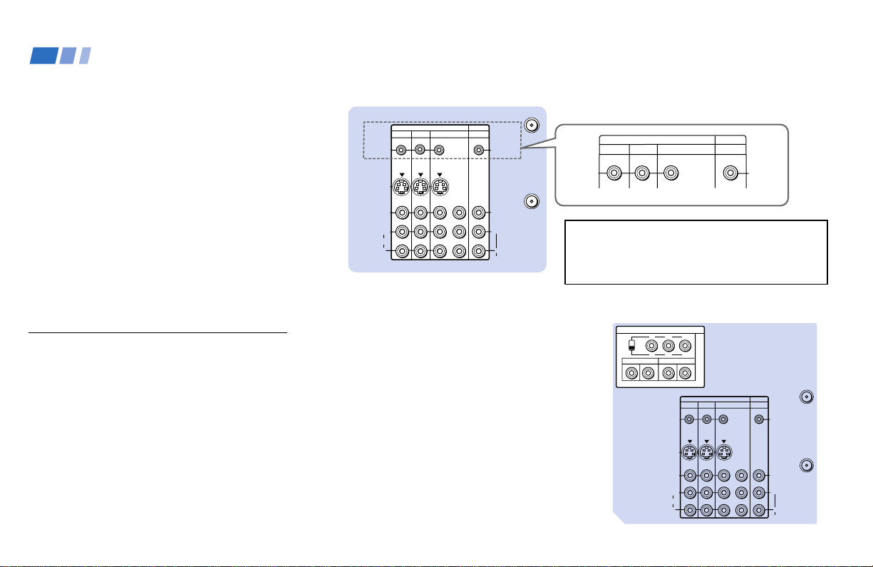
Using the CONTROL S feature
CONTROL S allows you to control the
projection TV and other Sony equipment
with one remote control.
To control other Sony equipment with the
projection TV's remote control, connect the
CONTROL S IN jack of the equipment to the
CONTROL S OUT jack on the TV’s upper
panel with the CONTROL S cable.
To control the projection TV with a remote
control for another Sony product, connect the
CONTROL S OUT jack of the equipment to
the CONTROL S IN jack on the TV’s upper
panel with the CONTROL S cable.
About the VIDEO 5 (HD) IN
jacks
The VIDEO 5 (HD) IN jacks on the TV’s
upper panel are designed to connect to the
HDTV output jacks of the equipment which
will accept the various HDTV formats (up to
1080i) scheduled to broadcast in the near
future. The projection TV will be capable of
connecting to a digital cable box TV decoder,
HDTV digital satellite system (DSS) decoder,
etc.
(Rear of projection TV)
WARNING!
Do not use the CONTROL S IN/OUT jacks
on the TV’s lower side panel.
It may cause a malfunction.
Installing and Connecting the Projection TV (continued)
(Rear of projection TV)
Before operating, set the YPBPR/RGB select
switch to YPBPR or RGB depending on the
HDTV equipment which is to be connected.
Note:
• The VIDEO 5 (HD) IN jacks are not
compatible with a computer’s 5BNC (R/
G/B/HD/VD) video output connectors.
Do not connect a computer to the VIDEO
5 (HD) IN jacks.
S VIDEO
S-LINK/
CONTROL S
OUT
S-LINK/
CONTROL S
IN
VIDEO
AUDIO
L
R
R
VIDEO
(MONO)
IN
SYNC AUDIO
OUT
VIDEO 1 VIDEO 3 VIDEO 4 (DVD)
VIDEO 5 (HD) IN
SELECT
Y
P
B
P
R
YP
B
P
R
YP
B
P
R
RGB
BGR
VD
HD
R
L
L
AUDIO
VHF/UHF
AUX
23
213
TV/VIDEO DTV ANT
TV ANT
MUTING
TV
OFF
WIDE MODE
CC
TV/DBS
PICTURE
MODE
JUMP GUIDE
DISPLAY
VIDEO AUDIO
ALTERNATE
POWER
SLEEP
DVD/
VTR
DBS/
CABLE
FUNCTION
DVD/VTR
DBS/CABLE
TV
Using the Remote Control
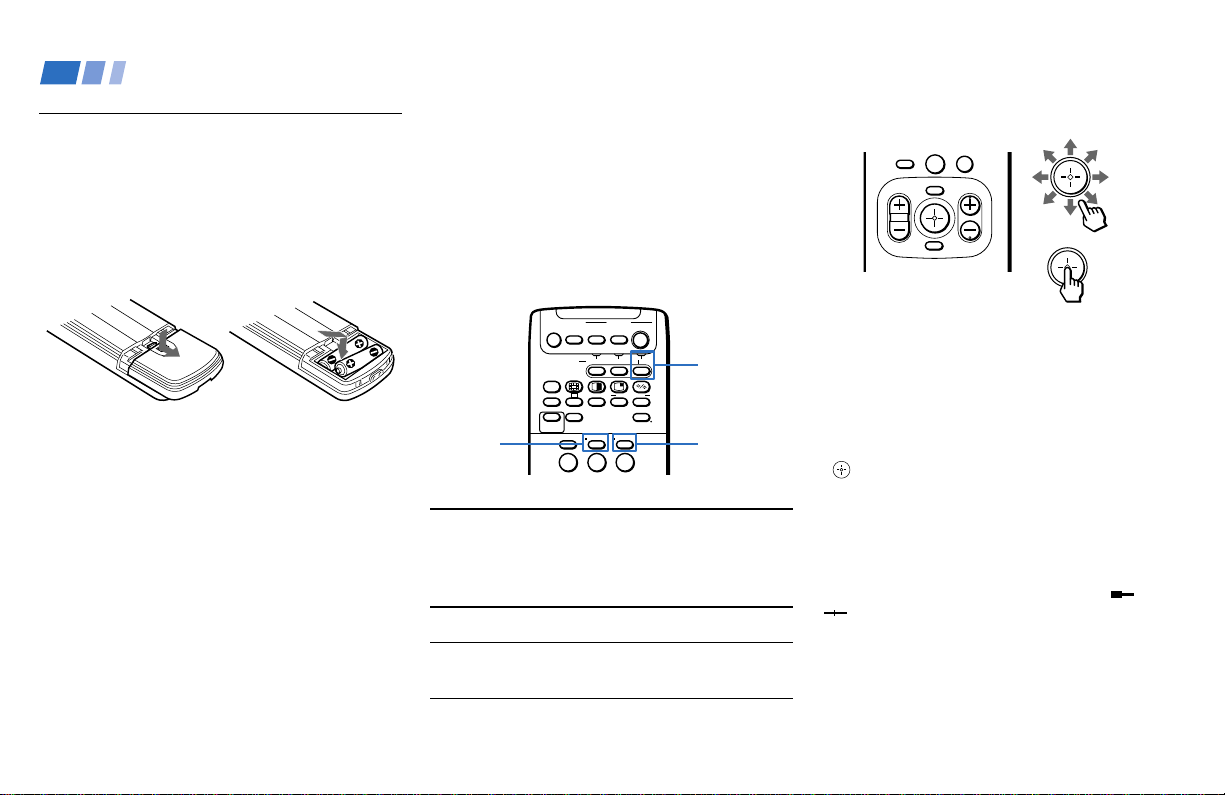
Inserting the batteries
Insert two size AA (R6) batteries (supplied)
by matching the + and – on the batteries to
the diagram inside the remote control’s
battery compartment.
Notes:
• Remove the batteries to avoid damage
from possible battery leakage whenever
you anticipate that the remote control
will not be used for an extended period.
• Handle the remote control with care.
Avoid dropping it, getting it wet, or
placing it in direct sunlight, near a heater
or where the humidity is high.
• Your remote control can be programmed to
operate most video equipment.
(see “Operating Video Equipment” on
page 72)
Basic Set Up
Using the remote control joystick
The supplied remote control has a joystick
which moves the on-screen selector in eight
directions. In most cases, moving the joystick
up, down, left or right will cause the selector
to move in the selected direction.
In some cases, the selector may move in
eight directions according to the function.
Pressing down on the center of the joystick
(
) will activate the selected item.
You may also move the joystick right to
activate a selected item. (There are some
exceptions to this option.)
Adjusting Sliders
When menu items present a slider ( or
), move the joystick up, down, left or
right to adjust the setting.
On Line Help/Instructions
Several menu windows will provide prompts
and instructions to assist you in navigating
through the different functions.
Select
0
Selecting a digital TV or
conventional TV program
The remote control functions both for digital
TV and conventional TV features. You will
need to switch the function of the remote
control according to your choice for viewing
either a digital TV or conventional TV
program.
TV
FUNCTION
indicator
TV ANT
DTV ANT
When you use
the remote
control for ......
The Digital TV
The
Conventional TV
Press ....
DTV ANT
TV ANT
so that the TV
FUNCTION
indicator lights
up in .........
green
red
Move
.

24
Setting Up the Projection TV
Automatically
The AUTO SET UP feature will allow you to
set all receivable channels.
Notes:
• Perform this function during the day, with
the antenna and/or cable properly
connected, to ensure that all available
channels will be broadcasting and
receivable.
• Before you perform AUTO SET UP for
conventional TV programs, make sure
that the input from ANT (not AUX) is
selected by pressing TV ANT until “AUX”
does not appear next to the channel
number.
• When you perform AUTO SET UP for
conventional TV programs, your
CHANNEL FIX and ON/OFF TIMER
settings will be erased.
• When you perform AUTO SET UP for
conventional TV programs, the settings in
the VIDEO menu except for “NR,”
“COLOR CORRECTION” and “DC
TRANSMISSION” and all the settings in
the AUDIO menu are reset to the factory
settings.
Basic Set Up (continued)
First, perform AUTO SET UP for
conventional TV programs. You can also set
the on-screen language.
After AUTO SET UP is completed for
conventional TV programs, Auto Program
will automatically run for digital TV
programs. Later, verify the Language and
Time Zone settings in your DTV Setup
Menu. (for details, see pages 34 and 35)
The AUTO SET UP feature does not apply
for installations that use a cable box for all
channel selection.
You can also set up the projection TV manually.
(see “Channel Setup” on page 33 for digital TV
channels, or “Using the CHANNEL SET UP
Menu” on page 54 for conventional TV channels)
25
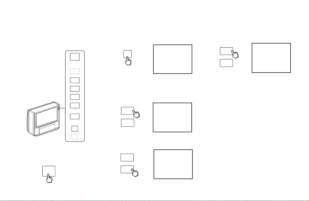
2 Press SET UP to display the AUTO SET
UP screen for conventional TV programs.
3 Press CHANNEL + to select English,
CHANNEL – to select Spanish.
The screen will change to reflect your
choice.
4 Press VOLUME – to select “AUTO SET
UP.”
5 Press CHANNEL + to preset
conventional TV channels automatically.
“AUTO PROGRAM” appears and the
projection TV starts scanning and
presetting conventional TV channels
automatically. While scanning, the
received conventional TV channel will be
displayed on the sub screen. When all the
receivable channels are stored, the lowest
conventional TV channel number will be
displayed.
AUTO PROGRAM
(continued)
CHANNEL
+
–
NO :
AUTO PROGRAM ?
CONTINUE TO
YES :
[ CH – ]
[ CH + ]
SET
UP
CHANNEL
+
–
VOLUME
+
–
Press
[
SET UP
]
to exit.
First please connect
the antenna.
AUTO SET UP :
ESPAÑOL :
ENGLISH :
[ VOL – ]
[ CH – ]
[ CH + ]
AUTO SET UP :
ESPAÑOL :
ENGLISH :
[ VOL – ]
[ CH – ]
[ CH + ]
Press
[
SET UP
]
to exit.
First please connect
the antenna.
First, perform AUTO SET UP for conventional
TV programs by using the buttons on the upper
right side panel on the front of the projection TV.
1 Press POWER to turn on the projection
TV.
POWER
TV/VIDEO
TV ANT/
DTV ANT
POWER
CHANNEL
VOLUME
+
–
+
–
AUTO
FOCUS
SET
UP

26
Basic Set Up (continued)
To perform AUTO SET UP again
Perform as described in steps 2–7 on pages
25 and 26.
Press SET UP again to exit.
Note:
• If there are no DTV channels saved in
channel memory (no DTV channels
found during “Auto Program” or “DTV
Auto Add”), the DTV Program Guide
cannot be accessed. Similarly, the “Name
& Logo” and “Skip/Add” features in the
Setup Menu cannot be accessed.
After AUTO SET UP for conventional TV
programs has been completed, Auto Program for
digital TV begins.
“Auto Program in Progress...” is displayed as
the projection TV scans and presets available
digital TV programs. When all the receivable
channels are stored, the lowest digital
channel number will be displayed.
6 Press DTV ANT on the remote control so
that the TV FUNCTION indicator lights
up in green momentarily.
The remote control functions for digital
TV programs.
7 Verify the Language and Time Zone
settings in your DTV Setup Menu. (for
details, see pages 34 and 35)
DTV ANT
Lights up in
green.
TVFUNCTION
Auto Program in Progress...
27
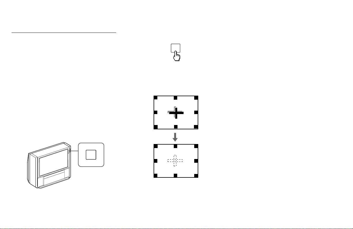
Press AUTO FOCUS.
The cross pattern appears and AUTO FOCUS
begins to work. The adjustment is completed
when the cross pattern becomes white.
AUTO
FOCUS
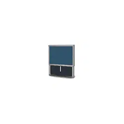
Adjusting the Convergence
Automatically (AUTO FOCUS)
The projection tube image appears on the
screen in three layers (red, green and blue). If
they do not converge, the color is poor and
the picture blurs.
Before you use your projection TV, be sure to
adjust the convergence.
The AUTO FOCUS feature allows you to
adjust the convergence automatically.
Tip
z
• It is recommended to perform AUTO FOCUS about
30 minutes after the projection TV is first turned on.
AUTO
FOCUS
To obtain an optimum
convergence
The optimum convergence alignment varies
with broadcasts in each wide screen mode
(see page 30 for DTV programs, and page 39
for conventional TV programs). It also varies
with broadcast formats for DTV programs.
Whenever you find that the picture blurs,
press AUTO FOCUS.
Note:
• You cannot perform any other functions
until AUTO FOCUS has completed its
cycle.
28
TV (FUNCTION)
p DTV ANT*
TV POWER
*
,
*
GUIDE*
CH +/–*
VOL +/–
JUMP*
REFER TO THE
ILLUSTRATION OF THE
REMOTE CONTROL ON THE
INSIDE FRONT COVER OF
THIS MANUAL AS YOU
REVIEW THIS CHART
Watching Digital TV
Many digital TV features can be accessed
directly through the remote control. The
following chart will explain the function of
some buttons found on your remote control.
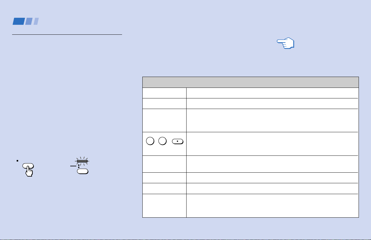
To use the remote control for
digital TV programs
First, press DTV ANT on the remote control
so that the TV FUNCTION indicator on the
remote control lights up in green
momentarily.
The remote control functions for digital TV
programs.
At the same time the DTV indicator on the
front of the projection TV lights up in green.
Make sure that the TV FUNCTION indicator
lights up in green each time you press the
buttons marked with an asterisk (*) that are
listed in the tables.
Using the White Labeled Buttons for Projection TV Operations
Activates the remote control for use with the projection TV.
Activates the remote control for use with digital TV programs.
Turns the projection TV on and off. If a video input indication (e.g. VIDEO 1,
VIDEO 2) appears on the screen, press TV/VIDEO until a channel number
appears.
Use for direct digital channel selection. Digital channels are indicated by the
use of a dot in the channel number. For example, to select subchannel 3 in
main channel 10 (channel number 10.3), press 1, 0, • (dot), 3 and ENTER.
Press to display the Program Guide. (see “Using Program Guide to Select
Subchannels” on page 31)
Press to scan through the channels (+ up or – down).
Press to adjust the volume (+ up or – down).
Press to alternate or
jump
back and forth between two digital channels. The
projection TV will jump between the current channel and the last channel
selected using the 0–9 and • (dot) buttons, CH+/– buttons or Program Guide.
and ENTER*
(continued)
0 9
-
Using Digital TV Features
DTV ANT
Lights up in
green.
TVFUNCTION

29
WIDE MODE
MUTING
SLEEP
DISPLAY*
TV/VIDEO
Using the White Labeled Buttons for Projection TV Operations
Press to watch 4:3 normal broadcasts in wide screen mode (16:9 aspect
ratio). (see “Using the Wide Screen Mode” on page 30)
Press to mute the sound. “MUTING” will appear on the screen and will dim
three seconds later. To restore sound, press again or press VOL +.
Press repeatedly until the projection TV displays the approximate time in
minutes (30, 60 or 90) that you want the projection TV to remain on before
shutting off automatically.
Cancel by pressing until “SLEEP OFF” appears.
Each press scrolls through the following indications:
Channel number, name and logo (if set) and current time
Closed caption
Display off
Press repeatedly to scroll through available video inputs:
TV, VIDEO 1, VIDEO 2, VIDEO 3, VIDEO 4 and VIDEO 5.
nn
n
REFER TO THE
ILLUSTRATION OF THE
REMOTE CONTROL ON THE
INSIDE FRONT COVER OF
THIS MANUAL AS YOU
REVIEW THIS CHART
Tip
z
You can adjust the picture and sound qualities using
the VIDEO (page 47) and AUDIO (page 49) menus
even when you are watching a digital TV program.
Before operating the menu, press TV (FUNCTION) so
that the TV FUNCTION indicator lights up in red.
After finishing the menu operation, press TV
(FUNCTION) again to make the TV FUNCTION
indicator light up in green.
PICTURE MODE
Press PICTURE MODE repeatedly to directly
choose one of five different video modes that
best suits the program you are watching.
You can also adjust the picture quality (such as
BRIGHTNESS, COLOR, etc.) for each mode to
suit your taste.
First select each MODE individually before
adjusting the picture quality.
VIVID: Select for enhanced picture contrast and
sharpness.
STANDARD: Select to display a standard
picture for normal viewing environments.
MOVIE: Select to display a finely detailed
picture for low light environments.
GAME: Select to display graphics such as a
video game.
PRO (Professional): Select to display a picture
with minimum enhancements.
For details, see “MODE” on page 47.
30
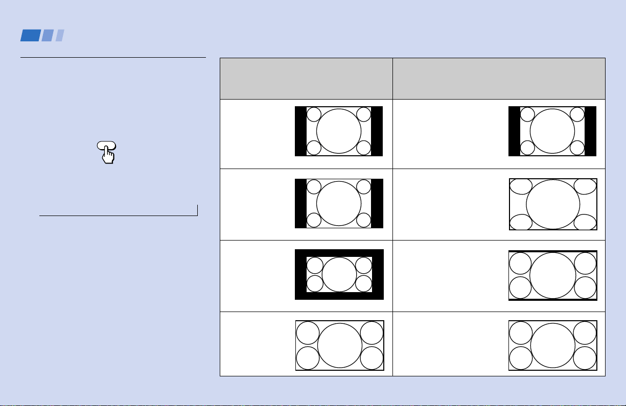
Using the Wide Screen Mode
The wide screen mode feature lets you watch
4:3 normal broadcasts in wide screen mode
(16:9 aspect ratio).
Press WIDE MODE on the remote control.
Each press scrolls through the following
modes:
NORMALnWIDE ZOOMnZOOMnFULL
Notes:
• If you watch a 4:3 aspect ratio picture in
NORMAL mode for long periods of time,
the black bands on both sides of the
picture may be permanently imprinted
onto the screen. We recommend that you
watch 4:3 pictures in WIDE ZOOM mode.
• The AUTO WIDE feature lets you select
the most suitable mode automatically for
a picture containing an aspect ratio
signal. (see “AUTO WIDE” on page 53)
• For ZOOM and WIDE ZOOM modes you
can adjust the vertical position of the
picture. (see “V CENTER” on page 53)
n
Using Digital TV Features (continued)
WIDE MODE
To watch the original
broadcasting screen sizes
shown below
DTV 4:3 aspect
ratio picture
DTV 4:3 aspect
ratio picture
Letter box movie
DTV 16:9 aspect
ratio picture
Press WIDE MODE to select the altered
screen sizes shown below
NORMAL
Select to return the 4:3
picture to normal mode.
WIDE ZOOM
Select to enlarge the 4:3
picture, while the upper and
lower parts of the picture are
condensed to fit the 16:9
screen.
ZOOM
Select to enlarge the 4:3
picture horizontally and
vertically to an equal aspect
ratio that fills the 16:9
screen.
FULL
No change
(DTV 16:9 aspect ratio
picture is always displayed
in FULL mode.)
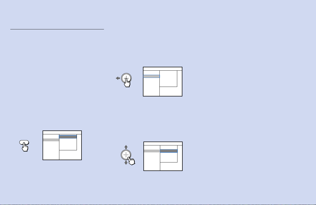
31
Using the Program Guide to
Select Subchannels
The Program Guide lets you select
subchannels from an on-screen list.
Subchannels are additional channels of
programming that are broadcast
simultaneously by a single network. For
example, channel 2, a main channel, might
include four subchannels (2.1, 2.2, 2.3 and
2.4) that are showing programs at the same
time.
1 Press GUIDE.
If the projection TV is tuned to a DTV
channel, the program guide appears. The
currently selected subchannel is
highlighted.
Channels that include subchannels include a dot,
followed by the number of the subchannel, such as
“2.1,” etc.
To check the channel number, press DISPLAY.
30 PBS
2 ABC
3 CBS
5 FOX
16 UPN
20 WB
25 NBC
.1 Drew Carey
.2 ABC movie
.3 News @ 8:00
.4 Ellen
CH 2.2
Program information in the program guide is
provided by the broadcasters. As a result, the
program guide may sometimes include only the
channel number without a program title, station
logo or description.
2 Move the joystick left to select the main
channel list.
3 Move the joystick up or down to select the
desired main channel number.
The tuning indicator appears. When the
selected main channel is tuned in, all of
the subchannels are listed. The first
subchannel is highlighted and its program
information appears at the top of the
screen.
4 Move the joystick up or down to select
the desired subchannel, and press
GUIDE.
The program guide will disappear.
To clear the program guide
without changing channels
Press GUIDE.
Note:
• If there are no DTV channels saved in
channel memory (no DTV channels found
during “Auto Program” or “DTV Auto
Add”), the DTV Program Guide cannot
be accessed.
GUIDE
.1 Drew Carey
.2 ABC movie
.3 News @ 8:00
.4 Ellen
30 PBS
2 ABC
3 CBS
5 FOX
16 UPN
20 WB
25 NBC
CH 2.2
3 CBS
5 FOX
16 UPN
20 WB
25 NBC
30 PBS
2 ABC
.1 The X-files
.2 Party of five
.3 Ally Mc Beal
.4 Simpsons
CH 5.1
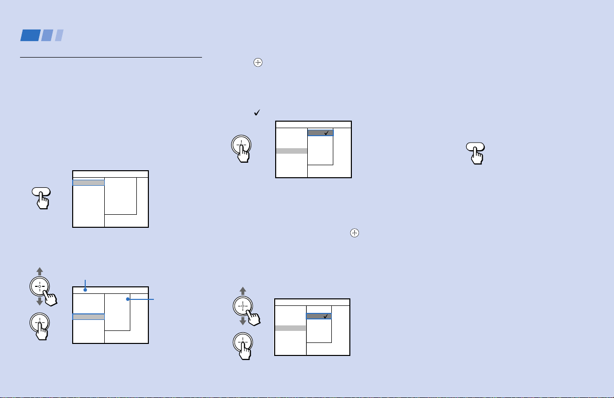
32
Learning Setup Menu
Selection
Use the MENU button to access the setup
menu and use the joystick to alter settings.
Use the following example to learn how to
modify settings.
1 Press the MENU button.
The setup menu appears.
2 Move the joystick up or down to select the
desired setup item.
Options for your selection (pop-up menu
on the right) will be displayed.
3 Press (press down on the center of the
joystick) to activate the selected item.
The currently selected option is
highlighted and marked with a check
mark (
).
You may also move the joystick right to
activate a selection.
4 Move the joystick up or down to select
the desired option, and press .
The selected option is highlighted and
marked with a check mark. The current
selection is displayed at the top of the on-
screen menu.
Some options may require further
operations.
For details, see each menu option.
5 Once you have completed all menu
settings, press MENU to exit the menu
screens.
You may also move the joystick left to
return to the previous screen.
To exit from the menus at any time
Press MENU.
Using Digital TV Features (continued)
Pop-up menu
Information about the selected
item is displayed here.
MENU
MENU
Channel Setup
Caption Vision
VTR Recording
Language
Auto Program
DTV Auto Add
Name and Logo
Skip/Add
Time Zone
Channel Setup
Caption Vision
VTR Recording
Language
English
Spanish
Channel Setup
Caption Vision
VTR Recording
Language
English
Spanish
Prog. de canales
Caption Vision
Videograbación
Idioma
Inglés
Español
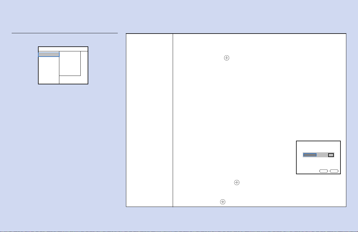
33
Using the Setup Menu
For detailed information on using the remote
control to modify menu settings, refer to
“Learning Setup Menu Selection” on page 32.
Note:
• If there are no DTV channels saved in
channel memory (no DTV channels found
during “Auto Program” or “DTV Auto
Add”), the “Name & Logo” and “Skip/
Add” features in the Setup Menu cannot
be accessed.
Channel Setup
Basic channel and
display options
Auto Program: Select to scan and preset digital channels automatically. Before
“Auto Program” process, a dialog box pops up with the message “Are you sure
you want to clear your existing channel list?” Move the joystick left or right to
select OK, and press to activate “Auto Program.” A tuning indicator appears
and the projection TV starts scanning and presetting digital channels
automatically. When all the receivable channels are stored, the lowest channel
is displayed and the tuning indicator disappears.
Note:
• If you currently have a list of programmed channels, or “Name and Logo” or
“Skip/Add” setting, they will be erased when you perform “Auto Program.”
DTV Auto Add: Select to preset additional digital channels as they become
available without erasing original channels (after you use Auto Program).
During the “DTV Auto Add” process, a tuning indicator appears and the
projection TV starts scanning and adding new digital channels. When scanning
is complete, the indicator disappears and the current channel re-appears.
Name and Logo: Select to add or change the station
name and logo.
When selected, a dialog box pops up.
1 Press CH +/– to select the desired channel.
2 Move the joystick left or right to select the station
name and the corresponding logo.
3 Move the joystick up or down—and then left or right—
to select OK, and press .
To clear the dialog box without changing the name and logo for the current
channel, move the joystick up or down—and then left or right—to select
“Cancel,” and press .
(continued)
Dialog box
Name and Logo
Press CH+/– to change channels.
Press
“ ”
to toggle Name/Logo.
OK
Cancel
Channel 30 FOX
FOX
Auto Program
DTV Auto Add
Name and Logo
Skip/Add
Time Zone
Channel Setup
Caption Vision
VTR Recording
Language
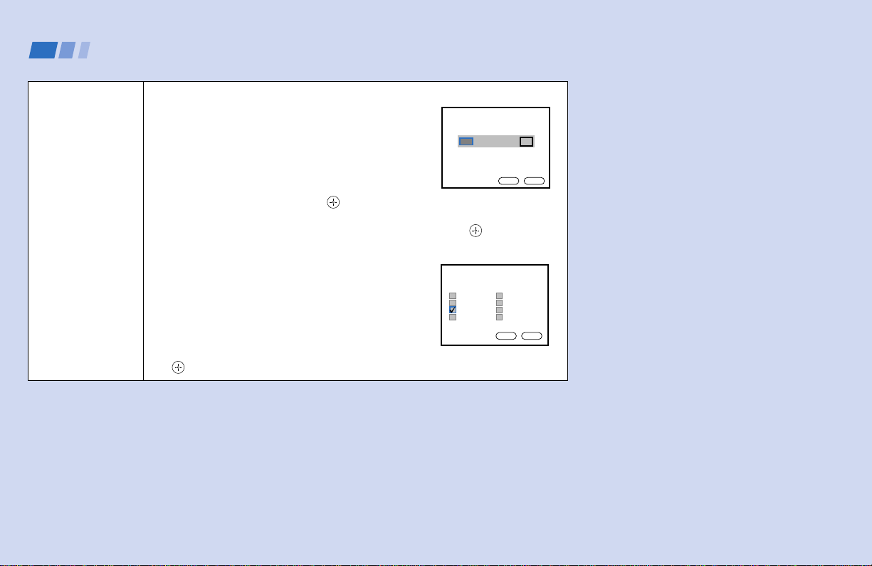
34
Using Digital TV Features (continued)
Channel Setup
Basic channel and
display options
Skip/Add: Select to erase or add channels from/to
your channel list.
When selected, a dialog box pops up.
1 Press CH +/– to select the desired channel.
2 Move the joystick left or right to select Skip to erase
a channel, or select Add to add a channel.
3 Move the joystick up or down—and then left or
right—to select OK, and press .
To clear the dialog box without erasing/adding a channel, move the joystick up
or down—and then left or right—to select “Cancel” and press .
Time Zone: Digital channels include time signals
based on the time zone. Select to choose a time zone
for your area.
When selected, the time zone dialog box pops up.
1 Move the joystick up, down, left or right to choose
your time zone.
A check mark will be given to your selection.
2 Move the joystick left or right to select OK, and press
.
(continued)
Dialog box
Dialog box
Skip / Add
Press CH+/– to change channels.
Press
“ ”
to toggle Skip/Add.
OK
Cancel
Skip CH30 FOX
FOX
Please select your appropriate
Time Zone
EASTERN
INDIANA(eastern)
CENTRAL
MOUNTAIN
ARIZONA(mountain)
PACIFIC
ALASKA
HAWAI
OK
Cancel

35
Caption Vision
Television closed
caption display
VTR Recording
Available for VCR
recording
Language
User’s preferred
language
Some programs are broadcast with Caption Vision
(closed caption).
To display closed caption
1 Select your language (English or Spanish) and then
press on the remote control.
2 Press DISPLAY until the Caption Vision appears.
Normally, set to Off.
Select On to record a digital program on a VCR
Notes:
• Since digital VCRs are not available at this time, you must set “VTR
Recording” to On before recording a digital TV program. This feature converts
the digital program to a standard broadcast for recording purposes. Once you
have finished recording your digital program, you will need to turn this feature
Off.
• Do not press the GUIDE, MENU or DISPLAY button on the remote control
while recording a digital program, otherwise the on-screen display information
will also be recorded.
Select from available languages (English or Spanish) to display the DTV Setup
menus in your language of choice.
English
Spanish
Channel Setup
Caption Vision
VTR Recording
Language
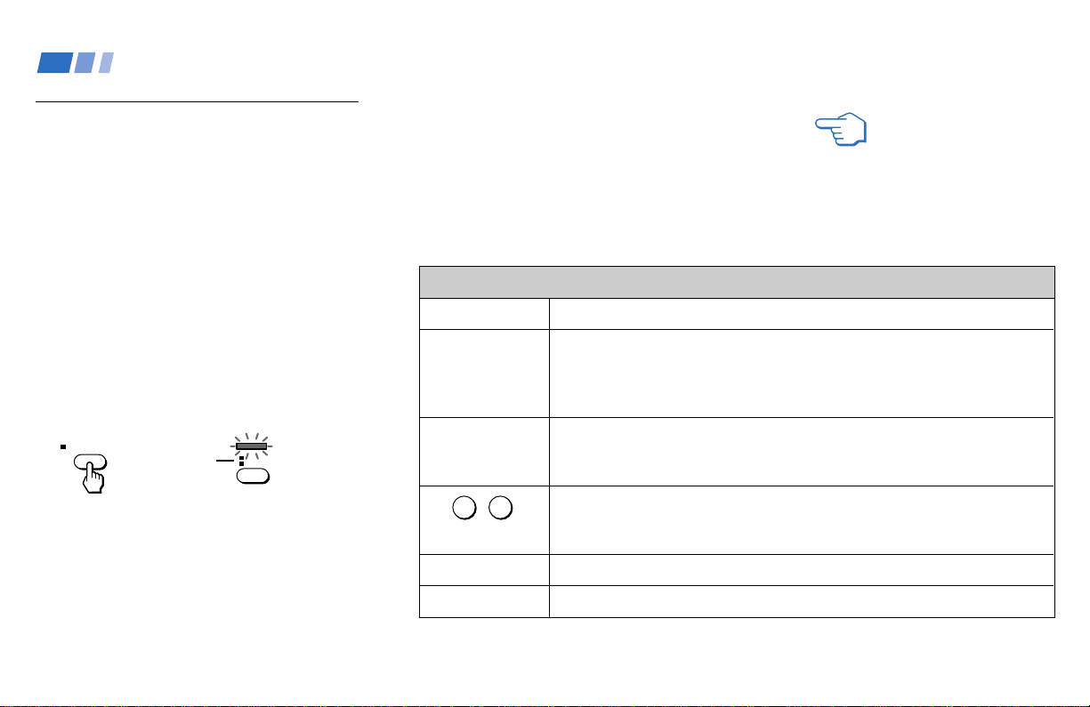
36
TV (FUNCTION)
p TV ANT
(AUX input)
TV POWER
CH +/–
VOL +/–
REFER TO THE
ILLUSTRATION OF THE
REMOTE CONTROL ON THE
INSIDE FRONT COVER OF
THIS MANUAL AS YOU
REVIEW THIS CHART
Watching Conventional TV
Many Conventional TV features can be
accessed directly through the remote control.
The following chart will explain the function
of some buttons found on your remote
control.
To use the remote control for
conventional TV programs (VHF/
UHF and AUX inputs)
First, press TV ANT on the remote control so
that the TV FUNCTION indicator on the
remote control lights up in red momentarily.
The remote control functions for
conventional TV programs.
Make sure that the TV FUNCTION indicator
lights up in red each time you press the
buttons listed in the tables.
Using the White Labeled Buttons for Projection TV Operations
Activates the remote control for use with the projection TV.
Press once to activate the remote control for use with conventional TV
programs. Next, each further press changes operation between the VHF/
UHF input and the AUX input. (for detailed connection information, see
“Cable and antenna” on page 7 or “Cable box and cable” on page 8)
Turns the projection TV on and off. If a video input indication (e.g., VIDEO 1,
VIDEO 2) appears on the screen, press TV/VIDEO until a channel number
appears.
Use for direct conventional TV channel selection. Press 0-9 to select a
channel (for example, to select channel 10, press 1 and 0). The channel will
change after 2 seconds, or you can press ENTER for immediate selection.
Press to scan through the channels (+ up or – down).
Press to adjust the volume (+ up or – down).
and ENTER
(continued)
0 9
-
Using Conventional TV Features
Lights up
in red.
TV ANT
TVFUNCTION
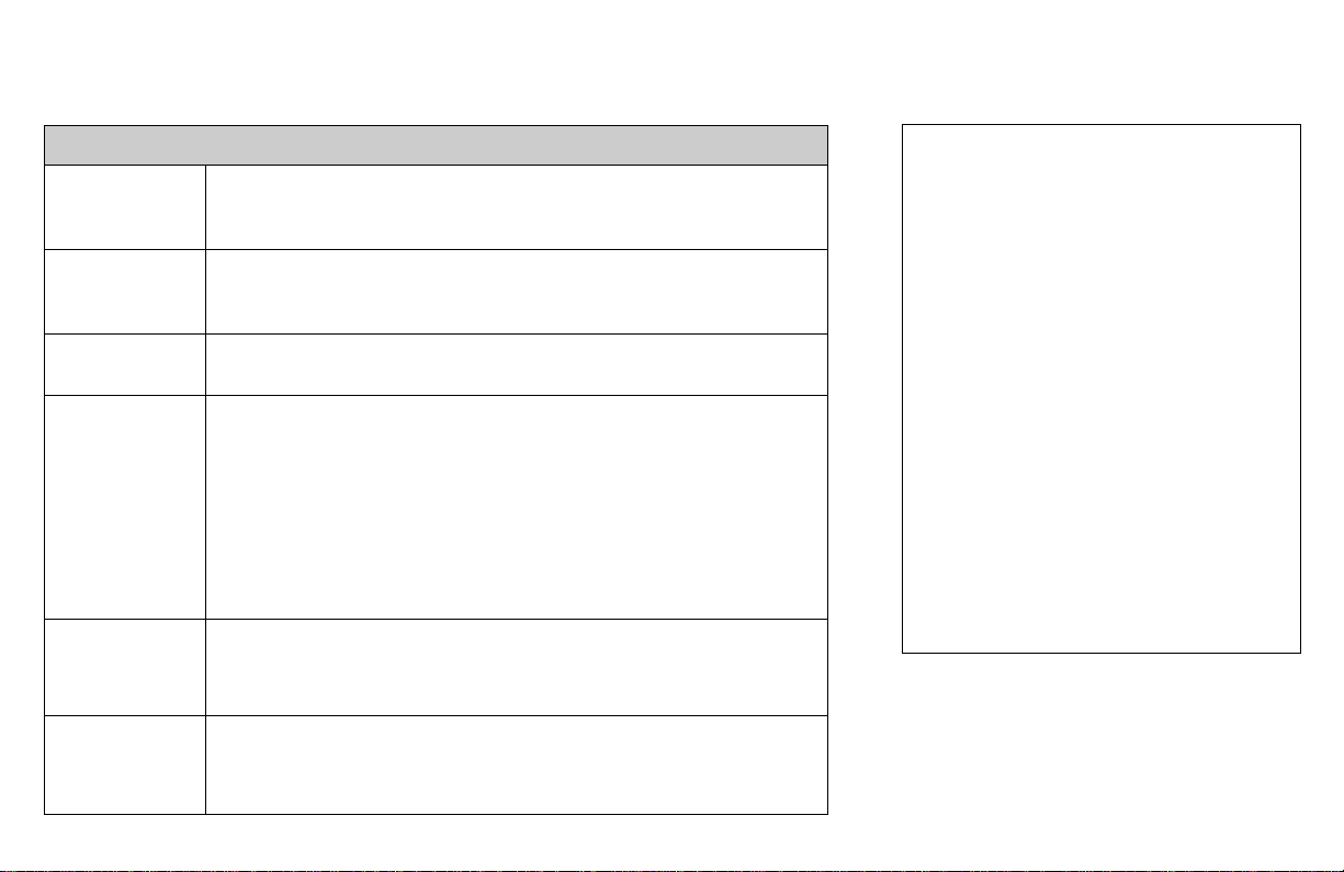
37
JUMP
WIDE MODE
(Wide screen
mode)
MUTING
FREEZE
(yellow labeled
button)
SLEEP
DISPLAY
Using the White Labeled Buttons for Projection TV Operations
Press to alternate or
jump
back and forth between two conventional TV
channels. The projection TV will jump between the current channel and the last
channel selected using the 0-9 buttons.
Press to watch 4:3 normal broadcasts in wide screen mode (16:9 aspect
ratio). (see “Using the Wide Screen Mode” on page 39)
Press to mute the sound. “MUTING” will appear on the screen and will
dim three seconds later. To restore sound, press again or press VOL +.
This is useful when you need to copy down information that appears on
the TV’s screen.
Press to
freeze
the picture.
Press again or press (OFF) to cancel.
If you select TWIN as a FREEZE MODE in the SET UP menu, you can
freeze the desired scene and display it on the left while viewing the
normal picture on the right. (see “FREEZE MODE” on page 63)
Note: If the frozen picture mode is not canceled for more than an hour,
the normal picture is resumed automatically.
Press repeatedly until the projection TV displays the approximate time in
minutes (30, 60, or 90) that you want the projection TV to remain on before
shutting off automatically.
Cancel by pressing until “SLEEP OFF” appears.
Press to display the channel number, current time, channel caption (if
set), and MTS mode (if SAP is selected). The SAP indication disappears
and the other indications dim three seconds later.
To turn the display off, press DISPLAY again.
PICTURE MODE
Press PICTURE MODE repeatedly to directly
choose one of five different video modes that
best suits the program you are watching.
You can also adjust the picture quality (such as
BRIGHTNESS, COLOR, etc.) for each mode to
suit your taste.
First select each MODE individually before
adjusting the picture quality.
VIVID: Select for enhanced picture contrast and
sharpness.
STANDARD: Select to display a standard
picture for normal viewing environments.
MOVIE: Select to display a finely detailed
picture for low light environments.
GAME: Select to display graphics such as a
video game.
PRO (Professional): Select to display a picture
with minimum enhancements.
For details, see “MODE” on page 47.
(continued)
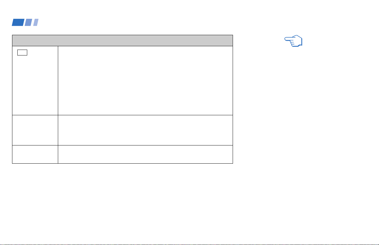
38
CC
TV/VIDEO
MTS
Using the White Labeled Buttons for Projection TV Operations
Press repeatedly to scroll through available displays:
Caption Vision
Displayed on the screen if the broadcaster offers this service. (see
“CAPTION VISION” on page 59)
XDS (Extended Data Service)
Displays a network name, program name, program type, program length,
program description, call letters and time of the show if the broadcaster
offers this service.
No display
“OFF” appears and the display is canceled.
Press repeatedly to scroll through available video inputs:
TV, VIDEO 1, VIDEO 2, VIDEO 3, VIDEO 4 and VIDEO 5
If you select SKIP as a VIDEO LABEL in the SET UP menu, your projection
TV will skip the video input you selected. (see “VIDEO LABEL” on page 61)
Press to scroll through the Multi-channel TV Sound (MTS) options.
(see “MTS” on page 49)
REFER TO THE
ILLUSTRATION OF THE
REMOTE CONTROL ON THE
INSIDE FRONT COVER OF
THIS MANUAL AS YOU
REVIEW THIS CHART
Using Conventional TV Features (continued)
Note:
• The GUIDE button does not function for
conventional TV programs.
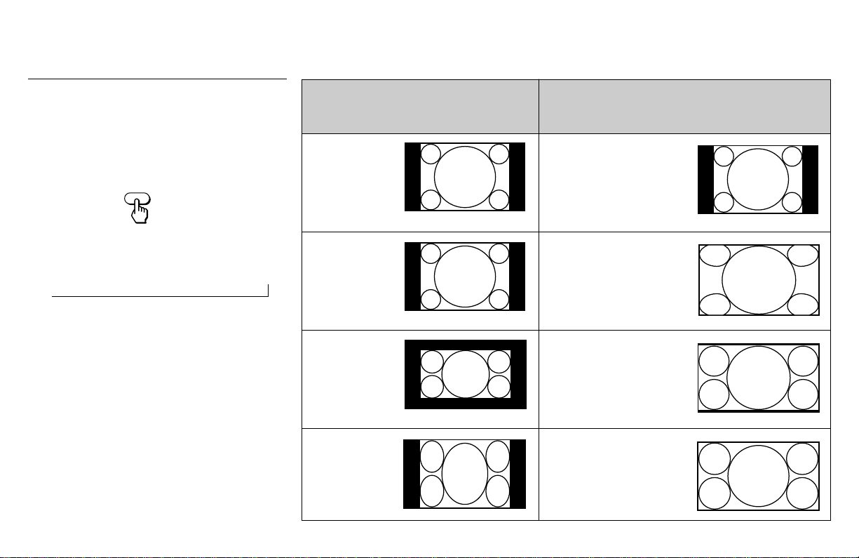
39
To watch the original
broadcasting screen sizes
shown below
Normal 4:3
aspect ratio
picture
Normal 4:3
aspect ratio
picture
Letter box movie
of a video tape or
a DVD disc
4:3 squeezed
video camera or
DVD picture
Using the Wide Screen Mode
The wide screen mode feature lets you watch
4:3 normal broadcasts in wide screen mode
(16:9 aspect ratio).
Press WIDE MODE on the remote control.
Each press scrolls through the following
modes:
NORMAL n WIDE ZOOM n ZOOM n FULL
Notes:
• If you watch a 4:3 aspect ratio picture in
NORMAL mode for long periods of time,
the black bands on both sides of the
picture may be permanently imprinted
onto the screen. We recommend that you
watch 4:3 pictures in WIDE ZOOM mode.
• The AUTO WIDE feature lets you select
the most suitable mode automatically for a
picture containing an aspect ratio signal.
(see “AUTO WIDE” on page 53)
• For ZOOM and WIDE ZOOM modes you
can adjust the vertical position of the
picture. (see “V CENTER” on page 53)
n
WIDE MODE
Press WIDE MODE to select the altered
screen sizes shown below
NORMAL
Select to return the 4:3
picture to normal mode.
WIDE ZOOM
Select to enlarge the 4:3
picture, while the upper and
lower parts of the picture
are condensed to fit the
16:9 screen.
ZOOM
Select to enlarge the 4:3
picture horizontally and
vertically to an equal aspect
ratio that fills the 16:9
screen.
FULL
Select to enlarge the 4:3
picture horizontally only, to
fill the 16:9 screen.
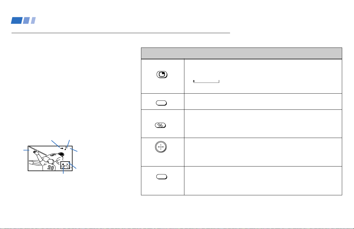
40
(white labeled
button)
(white labeled
button)
Press to display a window picture.
Each time you press this button, the picture size will change
(1/4 n1/9 n1/16).
Press (OFF) to close the window picture.
Press to change the location of the window picture (counterclockwise)
around the main picture.
Press to select either the main or window picture in order to change the
TV channel or video source using the white labeled buttons below. The
symbol “b” (or “B”) will appear to indicate which picture’s channel or input
mode can be changed.
To change the location of the window picture, move the joystick in any
direction and release it when the picture is in the desired location.
Press repeatedly to scroll through the available video inputs for the picture
on which the symbol “b” (or “B”) is displayed. (see “TV/VIDEO” on page
38)
The Picture-in-Picture (PIP) feature allows
you to view two channels simultaneously,
one in the full size “main” picture and one in
a smaller “window” picture.
You can move the window picture to any
location on the screen.
Note:
• The PIP feature is not available for the
inputs from VIDEO 5 IN and for digital
TV programs.
Tip
z
If you press RESET in PIP mode, the window picture
will move to the bottom right (factory-preset location).
Watching Two Programs at One Time — PIP
Using the Yellow Labeled Buttons for PIP Operations
Main
picture
The symbol “≥”
indicates which
picture's sound is being
received.
TV channel or input-
source mode for the
main picture (It will
dim in about 3
seconds.)
TV channel or input-
source mode for the
window picture (It
will dim in about 3
seconds.)
Window
picture
The symbol “b” or “B”
indicates which picture's
TV channel or input
source can be changed.
TV/VIDEO
POSITION
ACTIVE
10
6
Using Conventional TV Features (continued)
(continued)
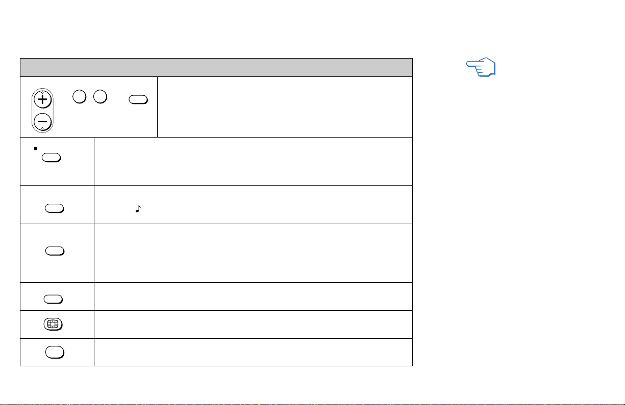
41
(white labeled button)
(white labeled
button)
Press to select the TV channel on which the symbol “b” (or “B”) is
displayed. (for details, see “Watching Conventional TV” on page
36)
Press to change between the VHF/UHF input and the AUX input for the picture on
which the symbol “b” (or “B”) is displayed.
Press to alternate sound between the main picture and the window picture. The
symbol " " will appear for a few seconds to indicate which picture’s sound is being
received.
This is useful when you need to copy down information that appears on the TV’s
screen.
Press to freeze the main and window pictures.
Press again to resume PIP viewing. Press (OFF) to cancel and resume normal TV
viewing.
Press to switch the audio and video of the main picture and the window picture.
Each time you press SWAP, the picture and sound of the two will be exchanged.
Press to access CHANNEL INDEX for direct channel selection. (see “Using
CHANNEL INDEX” on page 44)
Press to cancel the PIP function and return to normal viewing.
Using the Yellow Labeled Buttons for PIP Operations
Notes:
• If one of the pictures received through
PIP is snowy, the entire screen may
become unstable. In this case, erase the
snowy channel. (see “CHANNEL SKIP”
on page 54)
• You can change the wide screen mode of
the main picture only. The mode is not
available for the window picture.
• The 16:9 aspect ratio picture with ID-1 or
S1 is always displayed in FULL mode,
even when it is shown as the window
picture.
REFER TO THE
ILLUSTRATION OF THE
REMOTE CONTROL ON THE
INSIDE FRONT COVER OF
THIS MANUAL AS YOU
REVIEW THIS CHART
CH
or or
0 9
-
JUMP
and ENTER
AUDIO
FREEZE
SWAP
OFF
TV ANT
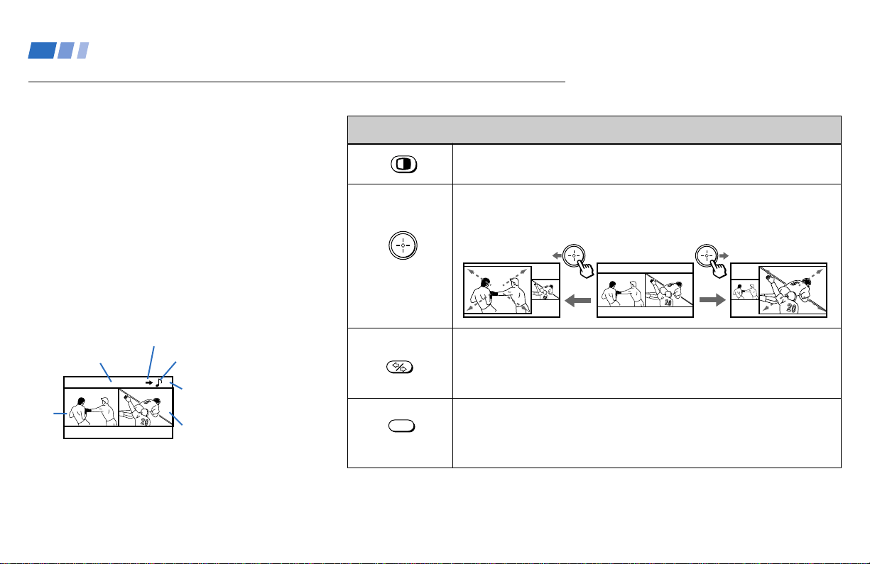
42
The Picture-and-Picture (P&P) feature allows
you to view two channels simultaneously,
both in a reduced size screen. The main
picture will appear on the right.
You can change the size of both pictures to
suit your personal preference.
Note:
• The P&P feature is not available for the
inputs from VIDEO 5 IN and for digital
TV programs.
Tip
z
If you press RESET in P&P mode, the right and left
pictures will be reset to the same size (factory-preset
size.)
Main picture
TV channel or input-
source mode for the main
picture (It will dim in
about 3 seconds.)
TV channel or
input-source mode
for the sub picture
(It will dim in
about 3 seconds.)
Sub
picture
Watching Two Programs at One Time — P&P (Twin View
TM
)
(white labeled
button)
(white labeled
button)
Press to display right (main) and left pictures.
Press (OFF) to close the sub picture.
Move the joystick right to zoom in on the right picture, and left to zoom in
on the left picture. Release at the desired size. The other picture will be
zoomed out simultaneously.
Press to select either the right or left picture in order to change the TV
channel or video source using the white labeled buttons below. The
symbol “b” (or “B”) will appear to indicate which picture’s channel or input
mode can be changed.
Press repeatedly to scroll through the available video inputs for the picture
on which the symbol “b” (or “B”) is displayed. (see “TV/VIDEO” on page
38)
Using the Yellow Labeled Buttons for P&P Operations
TV/VIDEO
ACTIVE
The symbol “≥” indicates
which picture's sound is
being received.
The symbol “b” or “B”
indicates which picture's TV
channel or input source can be
changed.
67
Using Conventional TV Features (continued)
(continued)
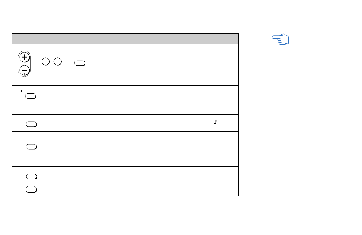
43
Notes:
• If one of the pictures received
through P&P is snowy, the entire
screen may become unstable. In this
case, erase the snowy channel. (see
“CHANNEL SKIP” on page 54)
• The right and left pictures (except for
the 16:9 aspect ratio signals with ID-1
or S1) are always displayed in an
aspect ratio of 4:3. The WIDE MODE
button on the remote control does not
function with the P&P mode.
• HD programs are always displayed
in an aspect ratio of 16:9.
REFER TO THE
ILLUSTRATION OF THE
REMOTE CONTROL ON THE
INSIDE FRONT COVER OF
THIS MANUAL AS YOU
REVIEW THIS CHART
(white labeled button)
(white labeled
button)
Press to select the TV channel on which the symbol “b” (or “B”) is
displayed. (for details, see “Watching Conventional TV” on page
36)
Press to change between the VHF/UHF input and the AUX input for the picture on
which the symbol “b” (or “B”) is displayed.
Press to alternate sound between the right and left pictures. The symbol " " will
appear for a few seconds to indicate which picture’s sound is being received.
This is useful when you need to copy down information that appears on the TV’s
screen.
Press to freeze both the right and left pictures.
Press again to resume P&P viewing or press (OFF) to cancel and resume normal
TV viewing.
Press to switch the audio and video of the right and left pictures.
Each time you press SWAP, the picture and sound of the two will be exchanged.
Press to cancel the P&P function and return to normal viewing.
Using the Yellow Labeled Buttons for P&P Operations
CH
or or
0 9
-
JUMP
and ENTER
AUDIO
FREEZE
SWAP
OFF
TV ANT
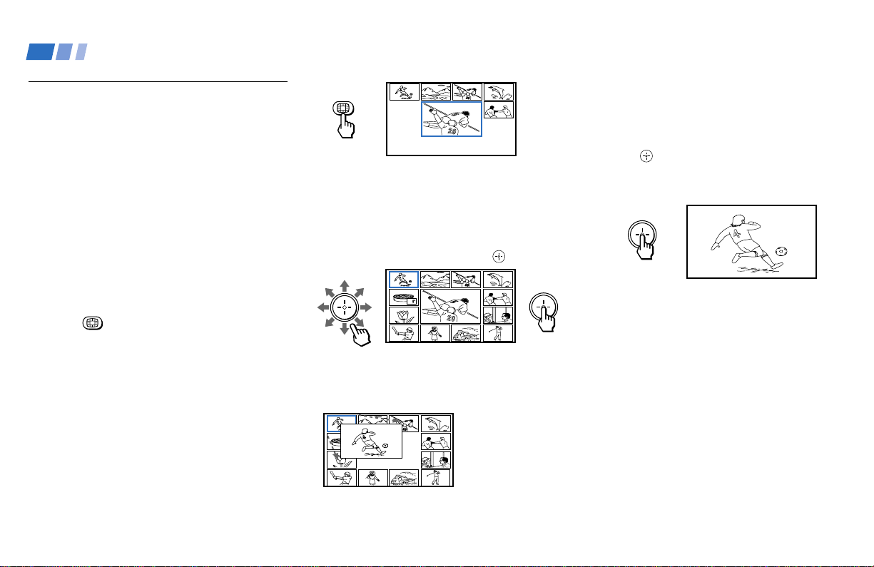
44
Using CHANNEL INDEX
You can use the CHANNEL INDEX feature
to display multiple channels and select one
directly.
Channels used for CHANNEL INDEX will
come directly from the TV’s list of receivable
channels (those set during AUTO
PROGRAM or through the CHANNEL SET
UP menu).
Note:
• The CHANNEL INDEX feature is not
available for the inputs from VIDEO 5 IN
and for digital TV programs.
1 Press .
The current channel will be reduced in
size and displayed in the center of the
screen in normal motion picture format in
FULL wide screen mode. The first twelve
receivable channels, displayed in FULL
wide screen mode, will appear one after
another, clockwise, around the center
picture. These small pictures are updated
in intervals of one second. The channel
number and channel caption (if set) on
the second and later appearances will
dim.
10
3 If you wish to view another channel,
repeat step 2.
To view the normal picture of the
selected channel, proceed to step 4.
4 Press .
The center picture will be enlarged for
normal viewing.
Notes:
• You cannot move the cyan frame until all
of the surrounding pictures appear.
• The projection TV will continually update
each of the surrounding pictures while
the CHANNEL INDEX screen is
displayed.
• Sound will only be heard from the center
picture.
• If one of the pictures received through
CHANNEL INDEX is snowy, the entire
screen may become unstable. In this case,
erase the snowy channel. (see
“CHANNEL SKIP” on page 54)
• If you leave the CHANNEL INDEX
screen displayed for an hour without any
additional operation, CHANNEL INDEX
is canceled and the normal picture
reappears.
A cyan-colored frame will appear to
indicate current channel selection.
2 Move the joystick in any direction to
move the cyan frame to the picture that
you wish to view, and press .
The selected channel will zoom in and
move to the center, and the sound of that
channel will be heard.
Reciipe
flour - - - - 2
sugar - - - 1/2
salt - - - - - 1/2
butter - - - 1
Reciipe
flour - - - - 2
sugar - - - 1/2
salt - - - - - 1/2
butter - - - 1
Using Conventional TV Features (continued)
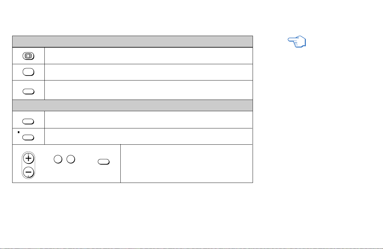
45
Press to display the next twelve receivable channels.
Press to cancel the current operation and return to normal TV viewing.
Press to freeze the center picture.
Press again to cancel the frozen picture and resume normal center picture viewing.
Using the Yellow Labeled Buttons for CHANNEL INDEX Operations
Using the White Labeled Buttons for Center Picture Operations
Press to scroll the center picture through the video inputs.
The surrounding channels will not change.
Press to switch the center picture between the VHF/UHF input and the AUX input.
Press to select a channel for the center picture.
(for details, see "Watching Conventional TV" on page
36)
and ENTER
or or
REFER TO THE
ILLUSTRATION OF THE
REMOTE CONTROL ON THE
INSIDE FRONT COVER OF
THIS MANUAL AS YOU
REVIEW THIS CHART
OFF
FREEZE
TV/VIDEO
JUMP
CH
0 9
-
TV ANT
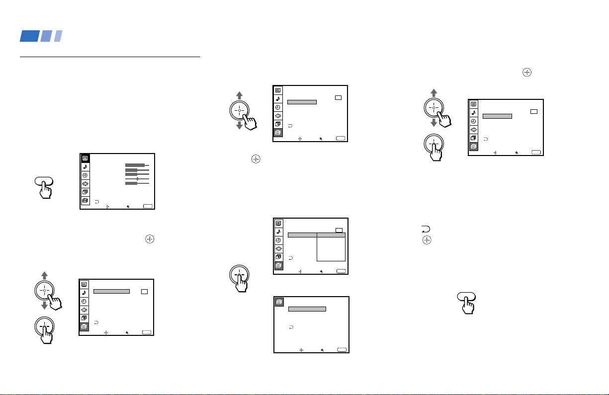
46
VIDEO LABEL
VIDEO1
VIDEO2
VIDEO3
VIDEO4
VIDEO1:
VIDEO2:
VIDEO3:
VIDEO4:
Move Select Exit
MENU
Learning Menu Selection
Use the MENU button to access a menu and
use the joystick to alter the settings. Use the
following example to learn how to modify
settings.
1 Press the MENU button.
The main menu appears.
2 Move the joystick up or down to highlight
the desired menu and press
(press
down on the center of the joystick) to
activate it.
You may also move the joystick right to
activate your selection.
3 Move the joystick up or down to
highlight the desired option.
4 Press (press down on the center of the
joystick).
Options for your selection (Pop-up menu
or Adjusting menu) will be displayed.
5 Move the joystick up or down to make
your selection and press to activate it.
The previous screen will reappear.
Some adjustment menus may require
further operations. For details, see each
menu option.
To return to the previous screen (except
for the slider adjustment menus), choose
at the bottom of the menu and press
or move the joystick left.
6 Once you have completed all menu
corrections, press MENU to exit the menu
screens.
To exit from the menus at any
time
Press MENU.
Pop-up menu
Adjusting menu
MENU
MENU
Using Conventional TV Features (continued)
VIDEO
MODE : VIVID
PICTURE
HUE
COLOR
BRIGHTNESS
SHARPNESS
TRINITONE : HIGH
DRC MODE :
HIGH
ADVANCED VIDEO
Move Select Exit
MENU
FREEZE MODE:
Move Select
Exit
MENU
SET UP
PARENTAL CONTROL
CAPTION VISION:
LANGUAGE:
SELECT OUT:
VIDEO LABEL
DIRECT PLAY
CC1
VIDEO1
MONITOR
VIDEO2
VIDEO3
VIDEO4
TV OUT
Move Select
Exit
MENU
SET UP
PARENTAL CONTROL
CAPTION VISION:
SELECT OUT: VIDEO1
LANGUAGE: ENGLISH
VIDEO LABEL
DIRECT PLAY
FREEZE MODE: NORMAL
CC1
Move Select
Exit
MENU
SET UP
PARENTAL CONTROL
CAPTION VISION:
SELECT OUT: MONITOR
LANGUAGE: ENGLISH
VIDEO LABEL
DIRECT PLAY
FREEZE MODE: NORMAL
CC1
Move Select
Exit
MENU
SET UP
PARENTAL CONTROL
CAPTION VISION:
SELECT OUT: MONITOR
LANGUAGE: ENGLISH
VIDEO LABEL
DIRECT PLAY
FREEZE MODE: NORMAL
CC1
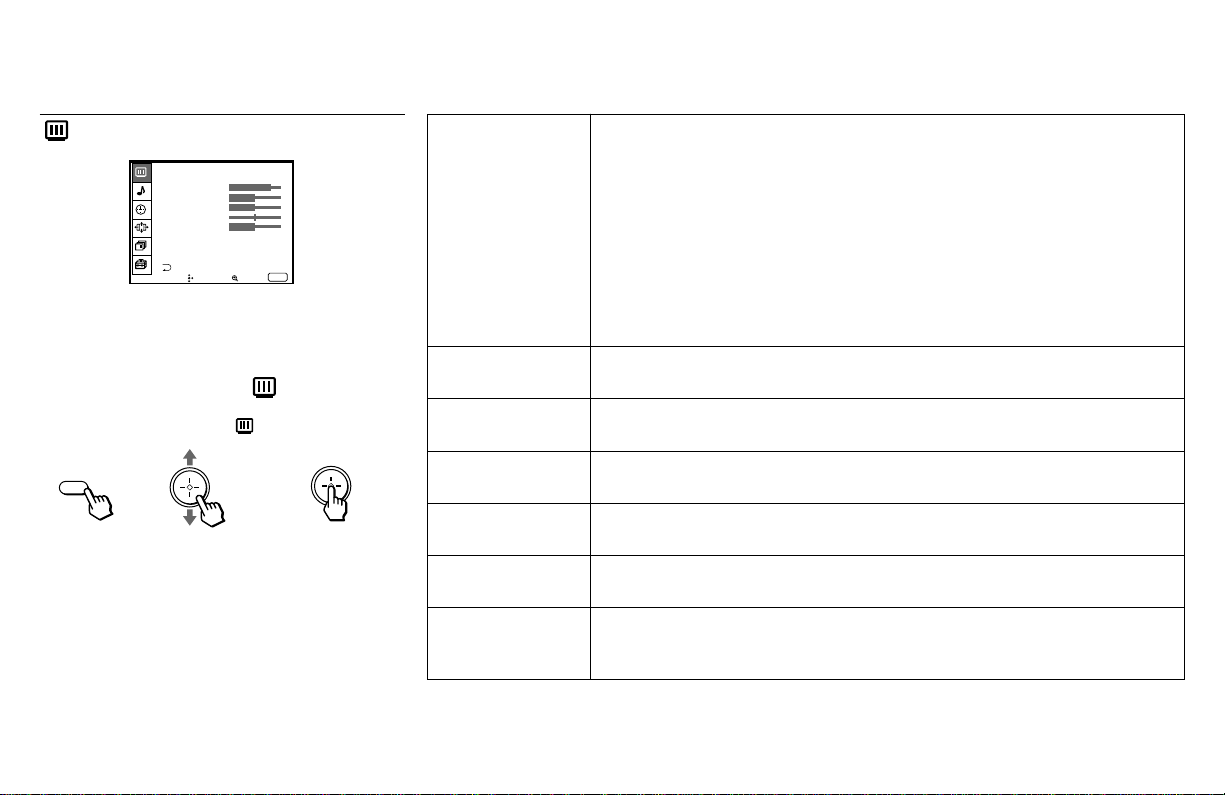
47
While in the VIDEO menu, move the joystick down to
scroll down to ADVANCED VIDEO to adjust
additional items, “DYNAMIC PICTURE,” “NR,”
“COLOR CORRECTION” and “DC
TRANSMISSION.” (see page 48)
To restore the factory settings
Press RESET on the remote control while the
VIDEO menu is selected. To restore each
MODE to the factory setting, press RESET
after selecting the mode to be reset.
MODE
Customized picture
viewing
PICTURE
Picture Adjustment
BRIGHTNESS
Picture Adjustment
COLOR
Picture Adjustment
HUE
Picture Adjustment
SHARPNESS
Picture Adjustment
TRINITONE
White Intensity
Adjustment
You can choose one of five different video modes that best suits the program you
are watching. You can also adjust the picture quality (such as BRIGHTNESS,
COLOR, etc.) for each mode to suit your taste. First select each MODE
individually before adjusting the picture quality.
VIVID: Select for enhanced picture contrast and sharpness.
STANDARD: Select to display a standard picture for normal viewing
environments.
MOVIE: Select to display a finely detailed picture for low light environments.
GAME: Select to display graphics such as a video game.
PRO (Professional): Select to display a picture with minimum enhancements.
Press PICTURE MODE on the remote control for direct selection of a MODE
setting.
Adjust slider right (up) to increase picture contrast.
Adjust slider left (down) to decrease picture contrast.
Adjust slider right (up) to brighten the picture.
Adjust slider left (down) to darken the picture.
Adjust slider right (up) to increase color intensity.
Adjust slider left (down) to decrease color intensity.
Adjust slider right (up) to increase the green tones.
Adjust slider left (down) to increase the red tones.
Adjust slider right (up) to sharpen the picture.
Adjust slider left (down) to soften the picture.
HIGH: Select to give the white colors a blueish tint.
MEDIUM: Select to give the white colors a neutral tint.
NTSC STD: Select to give the white colors a reddish tint.
Sliders
Using the VIDEO Menu
For detailed information on using the remote
control to modify menu settings, refer to
“Learning Menu Selection” on page 46.
To select the VIDEO menu:
Display / Highlight / Select
}
MENU
(continued)
Note:
• The items, “NR,” “COLOR CORRECTION” and “DC TRANSMISSION”
are not reset to the factory settings even if you press RESET.
VIDEO
MODE : VIVID
PICTURE
HUE
COLOR
BRIGHTNESS
SHARPNESS
TRINITONE : HIGH
DRC MODE :
HIGH
ADVANCED VIDEO
Move Select Exit
MENU

48
DRC MODE
Digital Reality
Creation
DYNAMIC
PICTURE
Black Intensity
Adjustment
NR
Noise Reduction
COLOR
CORRECTION
Color Ratio
Adjustment
DC
TRANSMISSION
Black Level
Adjustment
The DRC feature doubles both the vertical and horizontal information of the
conventional NTSC signal, allowing you to obtain a fine-detailed, realistic picture
with four-times higher density than the conventional NTSC picture.
HIGH: Use when viewing DVD, Hi8, Laser Disc, or DBS source.
LOW: Use when viewing VCR, CATV or ANT source.
GAME: Use when viewing graphics such as a video game.
Select ON to emphasize the black level and to produce a bolder dynamic picture.
Select OFF to cancel the feature.
Select ON to reduce picture noise.
Select OFF to cancel the feature.
Select ON to emphasize reds and blues.
Select OFF to reproduce skin tones.
Select ON to automatically improve the contrast ratio.
Select OFF to reproduce the black level with no compensation.
Tip
z
Since the fine-detailed DRC activated pictures contain
information four times larger than conventional pictures,
picture noise may appear. In this case, set NR to ON in
the ADVANCED VIDEO menu.
Notes:
• The following items can be adjusted for
each MODE setting (VIVID, STANDARD,
etc.) Once the adjustments are made, the
data is stored in the projection TV’s
memory and recalled whenever the
corresponding MODE setting is selected.
- PICTURE
- BRIGHTNESS
- COLOR
- HUE
- SHARPNESS
- TRINITONE
- DRC MODE
- DYNAMIC PICTURE
The “NR,” “COLOR CORRECTION,” and
“DC TRANSMISSION” settings, however,
are set independently of the MODE setting,
and remain in the ON or OFF position even
if the MODE setting is changed.
• Some shooting games which involve
pointing a light beam at the TV screen with
an electronic gun or rifle cannot be used
with this projection TV. For details, see the
instruction manual supplied with the video
game software.
Using Conventional TV Features (continued)
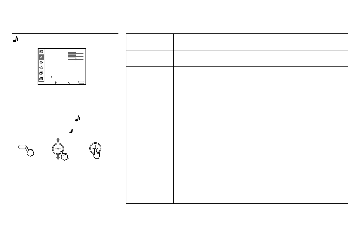
49
TREBLE
Sound Adjustment
BASS
Sound Adjustment
BALANCE
Sound Adjustment
MTS
Enjoy stereo,
bilingual and mono
programs
SPEAKER
Custom selection
of audio output
source
Adjust slider right (up) to increase high pitched sounds.
Adjust slider left (down) to decrease high pitched sounds.
Adjust slider right (up) to increase low pitched sounds.
Adjust slider left (down) to decrease low pitched sounds.
Adjust slider right (up) to emphasize right speaker volume.
Adjust slider left (down) to emphasize left speaker volume.
STEREO: Select for stereo reception when viewing a program broadcast in
stereo.
SAP: Select to listen to a bilingual broadcast. (non-SAP programs will be muted
when this feature is selected)
MONO: Select for mono reception. (use to reduce noise during stereo
broadcasts)
Quick MTS access: Press MTS on your remote control to cycle through the
MTS options as follows: (STEREO b SAP b MONO b STEREO)
ALL ON: Select to listen to the sound from the projection TV speakers alone.
L/R OFF: Select to turn off the projection TV left and right speakers and listen to
the left and right channel sounds through a separate audio system’s
speakers.
ALL OFF: Select to turn off the projection TV speakers and listen to the
projection TV’s sound only through an external audio system’s speakers.
CENTER IN: Select to use the projection TV center speaker as center speaker
when you connect an amplifier with a Dolby Pro Logic/Dolby Digital decoder.
(see “Connecting an amplifier that supports Dolby Pro Logic/Dolby
Digital decoder” on page 19)
}
Sliders
Using the AUDIO Menu
For detailed information on using the remote
control to modify menu settings, refer to
“Learning Menu Selection” on page 46.
To select the AUDIO menu:
Display / Highlight / Select
To restore the factory settings
Press RESET on the remote control while the
AUDIO menu is selected.
MENU
AUDIO
TREBLE
BASS
BALANCE
MTS : STEREO
SPEAKER : ALL ON
SURROUND : OFF
SURROUND LEVEL
Move Select Exit
MENU
(continued)

50
SURROUND
Customizes
surround sound
effects based on
the program’s
audio type
SURROUND
LEVEL
Speaker volume
adjustment for
surround modes
SURROUND can only be set when SPEAKER is set to ALL ON or L/R OFF.
aa
aa
a PRO LOGIC: Produces superb theater-like surround effects. Most effective
for programs encoded in Dolby surround.
aa
aa
a 3 STEREO: Produces a dynamic three dimensional sound without using the
rear speakers. The sound of the rear channel is output from the front
speakers.
SIMULATED: Adds a surround-like effect to mono programs.
LIVE: Produces surround effects with the atmosphere of a concert hall.
GAME: Produces maximum audio impact. Most effective for video games.
OFF: Normal stereo or mono reception.
After selecting one of the surround modes, adjust the volume of each speaker
so that the sound will be even and natural. (see “Adjusting the Speaker Volume
for Customized Surround Mode” on page 51)
Using Conventional TV Features (continued)
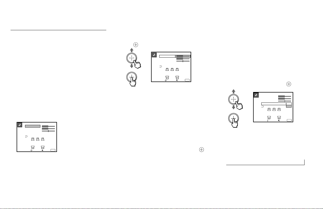
51
Adjusting the speaker volume
using the test tone
The TEST TONE feature makes it easier to
adjust the volume level. You can use this
feature for aPRO LOGIC and a3 STEREO
modes only.
1 With the SURROUND LEVEL window
open, move the joystick up or down to
select TEST TONE and press
.
2 Move the joystick up or down to select
ON.
A test tone will be output from each
speaker in sequence:
Front left nCenter nFront right nRear
To turn off the test tone, select OFF.
3 Follow steps 2 through 4 in “Adjusting
the speaker volume.”
Adjusting the Speaker
Volume for Customized
Surround Mode
After you set SURROUND to one of the
modes, adjust the volume of the front, center
and rear speakers to the same level so that
the projection TV’s sound will be even and
natural. For aPRO LOGIC and a3
STEREO, adjust the speaker volume using
the test tone feature.
Adjusting the speaker volume
1 Select SURROUND LEVEL from the
AUDIO menu. (see pages 49 and 50)
2 Move the joystick up or down to select
the speaker for volume adjustment and
press .
CENTER: Select to adjust the level of the
center speaker. (not available for
SIMULATED)
REAR: Select to adjust the level of the rear
speakers. (not available for
a3 STEREO)
BALANCE: Select to adjust the balance
between the right and left speakers.
3 Move the joystick up, down, left or right
to adjust the volume level and press .
4 Use the joystick to select other speakers
and to adjust the volume levels.
n
aPRO-LOGIC
REAR
BALANCE
TEST TONE : OFF
CENTER
Move Select Exit
MENU
aPRO-LOGIC
REAR
BALANCE
TEST TONE : OFF
CENTER
Move Select Exit
MENU
REAR
BALANCE
TEST TONE : ON
OFF
CENTER
aPRO-LOGIC
Move Select Exit
MENU
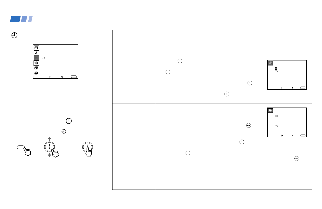
52
DAYLIGHT
SAVING
Automatically
adjusts the time.
CURRENT
TIME
Necessary for the
TIMER.
ON/OFF TIMER
Wake up or
scheduled viewing.
Using the TIMER Menu
After setting the clock you can use the timer
to turn the projection TV on and off.
For detailed information on using the remote
control to modify menu settings, refer to
“Learning Menu Selection” on page 46.
To select the TIMER menu:
Display / Highlight / Select
Tip
z
Set daylight saving time before setting the clock. Any
loss of power will cause these settings to be erased.
Spring: Select YES to compensate for Daylight Saving Time.
The current time automatically moves ahead one hour.
Fall: Select NO at the end of Daylight Saving Time.
The current time moves back one hour.
1 Press , then move the joystick up or down until
the current day (MON-SUN) is displayed, and press
.
2 Move the joystick up or down until the current hour
(01-12) and AM/PM is displayed, and press .
3 Move the joystick up or down until the current minute
(00-59) is displayed, and press .
The Clock has now started. Press MENU to exit.
1 Select the desired timer (1 or 2).
2 Move the joystick up or down until the desired day
(MON-SUN) or range of days (EVERY SUN-SAT or
EVERY MON-FRI) is displayed, and press .
3 Move the joystick up or down until the time (hours
and minutes) that you want the projection TV to
remain on is displayed, and then press .
4 Move the joystick up or down to set the time duration (maximum of 6 hours)
and press .
5 Move the joystick up or down to select the desired channel and press .
The timer is now set. The TIMER/STAND BY indicator on your projection TV
will be lit.
Press MENU to exit.
To cancel your timer setting, select timer 1 or 2 and press
RESET while in the ON/OFF TIMER window.
Performing AUTO PROGRAM will
erase all TIMER settings.
MENU
CURRENT TIME
–––
Move Select
Exit
MENU
––: –AM–
ON / OFF TIMER
2.
––––––
––: ––AM
–
Hch
–––
––––
––: ––AM
–
Hch
–––
Move Select
Exit
MENU
SUN
12: 0AM0
1.
TIMER
DAYLIGHT SAVING : NO
CURRENT TIME
ON / OFF TIMER
– – –
– – : – AM–
Move Select Exit
MENU
Using Conventional TV Features (continued)
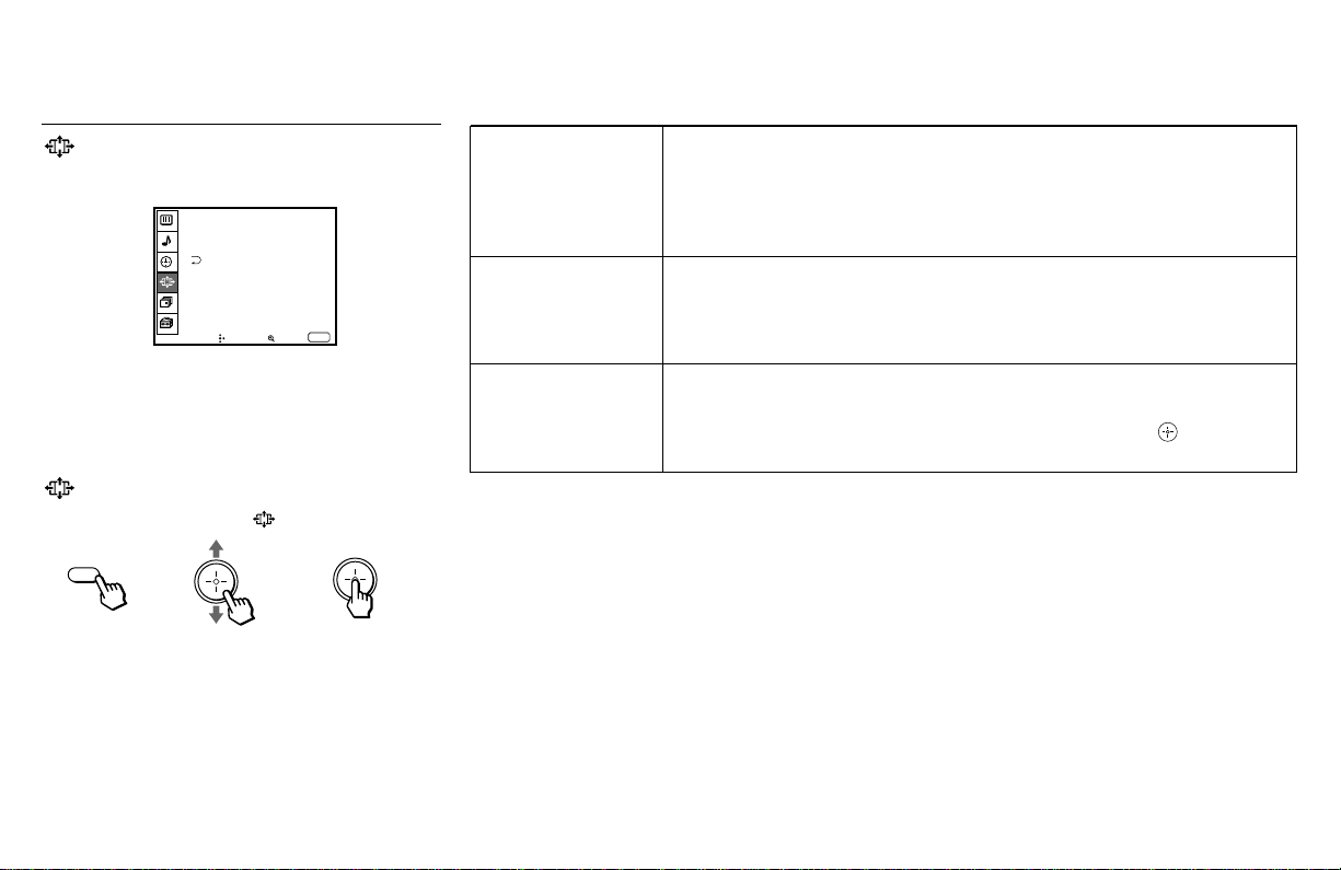
53
AUTO WIDE
Automatically
selects the wide
screen mode
WIDE MODE
Manually selects
the wide screen
mode
V CENTER
Adjusts the
position of the
picture
Using the WIDE SCREEN
MODE Menu
For detailed information on using the remote
control to modify menu settings, refer to
“Learning Menu Selection” on page 46.
To select the WIDE SCREEN MODE
Menu:
Display / Highlight / Select
To restore the factory settings
Press RESET on the remote control while the
WIDE SCREEN MODE menu is selected.
Select ON to automatically display the picture with an ID-1 or S1 (aspect ratio
recorded) signal in an optimum wide screen mode; normal 4:3 picture in
NORMAL, letterbox picture in ZOOM, and 4:3 squeezed picture in FULL.
Select OFF if you want to choose the wide screen mode manually by pressing
the WIDE MODE button.
You can select NORMAL, WIDE ZOOM, ZOOM or FULL for the 4:3 or
letterbox picture to fill the 16:9 screen manually by pressing the WIDE MODE
button. (for details on each mode, see “Using the Wide Screen Mode” on page
39)
Allows you to move the picture vertically within the screen (available only in
ZOOM and WIDE ZOOM modes).
Move the joystick up or down to move the picture, and press .
MENU
WIDE SCREEN MODE
AUTO WIDE : ON
WIDE MODE : NORMAL
V CENTER : 0
Move Select Exit
MENU
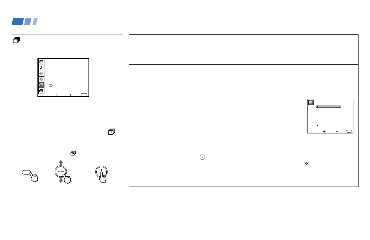
54
CABLE
Cable system
setting
AUTO
PROGRAM
Automatic
channel presetting
CHANNEL
SKIP
Skips unnecessary
channels
Select ON if your projection TV is connected to a cable system.
Select OFF if your projection TV is connected to an antenna.
AUTO SET UP will set CABLE to OFF automatically if a cable channel is not
available.
Select YES to signal the projection TV to automatically program all receivable
conventional TV channels. When all the receivable channels are stored, the
lowest numbered channel is displayed.
Select NO to cancel AUTO PROGRAM.
After AUTO SET UP, you can erase unnecessary
conventional TV channels from the channel preset
memory.
With the CHANNEL SKIP window open:
1 Move the joystick up or down to select the desired
channel. You can view the channel that is selected
with the CHANNEL SKIP menu in the center sub
screen. You can also use CH +/– or 0–9 and
ENTER buttons.
2 Press .
3 Move the joystick up or down to select YES, and press .
The selected channel will be erased.
If you want to re-enter the skipped channel, follow the steps above and select
NO.
Using the CHANNEL SET
UP Menu
For detailed information on using the remote
control to modify menu settings, refer to
“Learning Menu Selection” on page 46.
To select the CHANNEL SET UP
menu:
Display / Highlight / Select
MENU
Using Conventional TV Features (continued)
(continued)
CHANNEL SET UP
CHANNEL SKIP
CHANNEL CAPTION
CABLE : ON
AUTO PROGRAM
FAVORITE CHANNEL : AUTO
CHANNEL FIX : OFF
Move Select Exit
MENU
CHANNEL SKIP
Select a channel
2 :
3 :
4 :
5 :
6 :
7 :
8 :
NO
1 :
Move Select Exit
MENU
NO
NO
NO
NO
NO
NO
NO

55
CHANNEL
CAPTION
Easy recognition
of the channel
you are watching
FAVORITE
CHANNEL
User’s favorite
channels
You can add a caption for up to 32 channels of both
VHF/UHF and AUX inputs.
With the CHANNEL CAPTION window open:
1 Press and then move the joystick up or down to
select the desired channel. You can view the channel
that is selected with the CHANNEL CAPTION menu
in the center sub screen.
2 Press .
3 Move the joystick up or down to display the first letter
or number of the caption and press to select it.
Repeat until up to four digits are selected.
4 Press .
To erase a caption, press RESET.
The FAVORITE CHANNEL feature enables easy access to the eight channels that
you preset (or the last channel that you were watching).
(for details on how to set up this feature, see "Setting and Selecting FAVORITE
CHANNEL" on page 57)
CHANNEL CAPTION
CAPTION : – –– –
Move Select
Exit
MENU
CHANNEL : – – –
(continued)

56
CHANNEL FIX
Locks selection of
your projection
TV’s input when
used in conjunction
with external
equipment such as
a cable box, AV
receiver, etc.
2-6: When the cable box is connected to the VHF/UHF input, you can fix the TV’s
input to one of the channels between 2 and 6. Press DBS/CABLE (FUNCTION)
and then CH +/– to change the cable box channels.
AUX 2-6: Use this when a cable box is connected to AUX, and a cable or antenna
is connected to VHF/UHF.
VIDEO 1: Use this when you have connected external video equipment (e.g. AV
receiver) and you want the projection TV’s input fixed to it.
OFF: When you want to switch CHANNEL FIX off.
If the projection TV is in the AUX mode when you turn CHANNEL FIX off, press
ANT to return to UHF input mode.
TIMER settings are erased when CHANNEL FIX is set.
Note:
• You cannot change channels with the TV’s
tuner when you set CHANNEL FIX. If
you want to use the TV’s tuner while
fixing the TV’s input to VIDEO 1, use the
SET UP menu to set SELECT OUT to TV
OUT. (see “SELECT OUT” on page 60)
Using Conventional TV Features (continued)
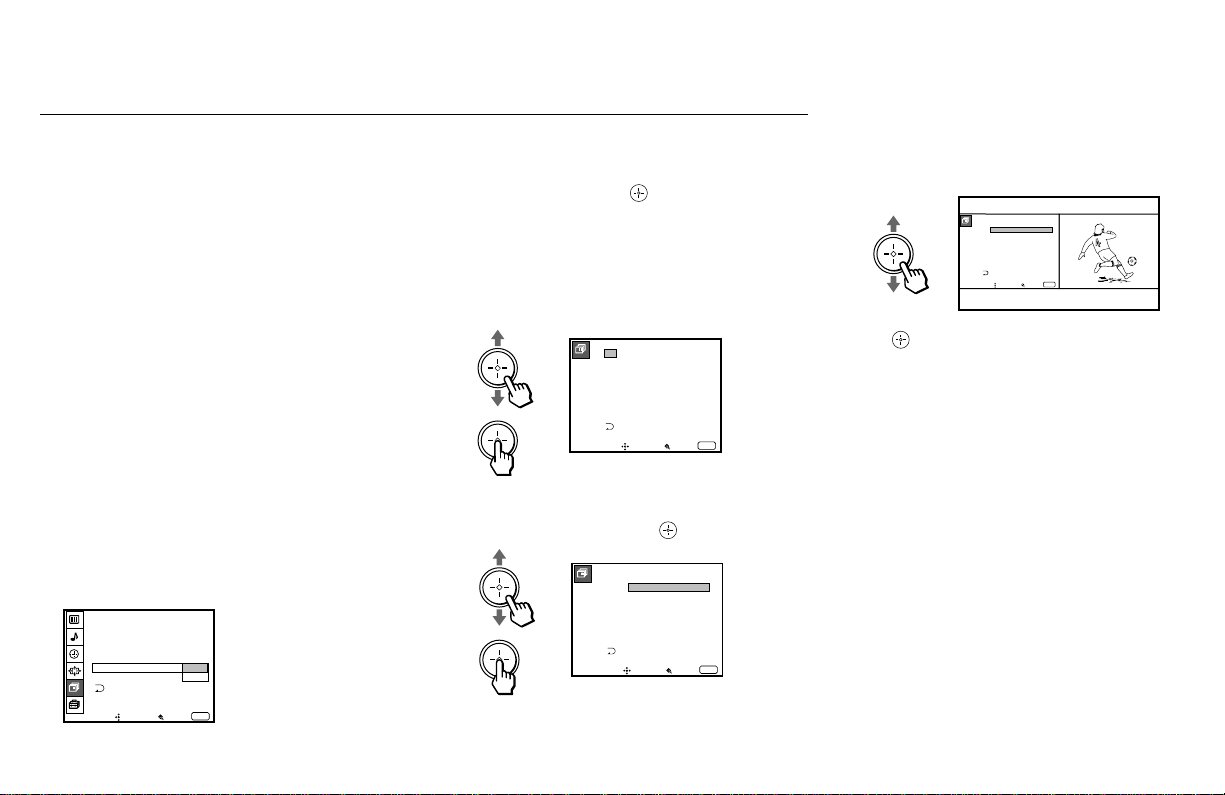
57
The FAVORITE CHANNEL feature of your
projection TV enables easy access to the eight
channels that you preset (or the last channel
that you were watching).
Your FAVORITE CHANNEL options can be
set automatically or manually.
The factory setting for FAVORITE
CHANNEL is AUTO.
When FAVORITE CHANNEL is set to
AUTO, the last eight channels selected with
the 0–9 buttons will be set as FAVORITE
CHANNEL options. If you want to input
your own selections as FAVORITE
CHANNEL settings, set to MANUAL.
Setting FAVORITE CHANNEL
manually
1 Select FAVORITE CHANNEL from the
CHANNEL SET UP menu. (see pages 54
and 55)
2 Move the joystick up or down to select
MANUAL and press .
The FAVORITE CHANNEL menu will
appear. If you set CHANNEL CAPTION
names (e.g. CNN, HBO), they will also be
displayed. (see “CHANNEL CAPTION”
on page 55)
3 Move the joystick up or down to select a
position (1–8), and press .
4 Move the joystick up or down to select a
channel.
You have now selected a favorite channel.
5 Press and use the joystick to program
other favorite channels. (Follow steps 3
and 4.)
6 Press MENU when you have finished.
Your favorite channels are now ready for
use.
Setting and Selecting FAVORITE CHANNEL
FAVORITE CHANNEL
Select a position
2 .
3 .
4 .
5 .
6 .
7 .
8 .
1 .
2
10
22
30
40
52
125
1
SPTN
CNN
Move Select Exit
MENU
FAVORITE CHANNEL
Select a channel
2 .
3 .
4 .
5 .
6 .
7 .
8 .
1 .
2
10
22
30
40
52
125
SPTN
1 CNN
Move Select Exit
MENU
FAVORITE CHANNEL
Select a channel
2 .
3 .
4 .
5 .
6 .
7 .
8 .
Move Select
Exit
MENU
1 .
125
10
22
30
40
52
125
SPTN
1 CNN
(continued)
Move Select Exit
MENU
CHANNEL SET UP
CHANNEL SKIP
CHANNEL CAPTION
CABLE : ON
AUTO PROGRAM
FAVORITE CHANNEL : AUTO
CHANNEL FIX :
MANUAL
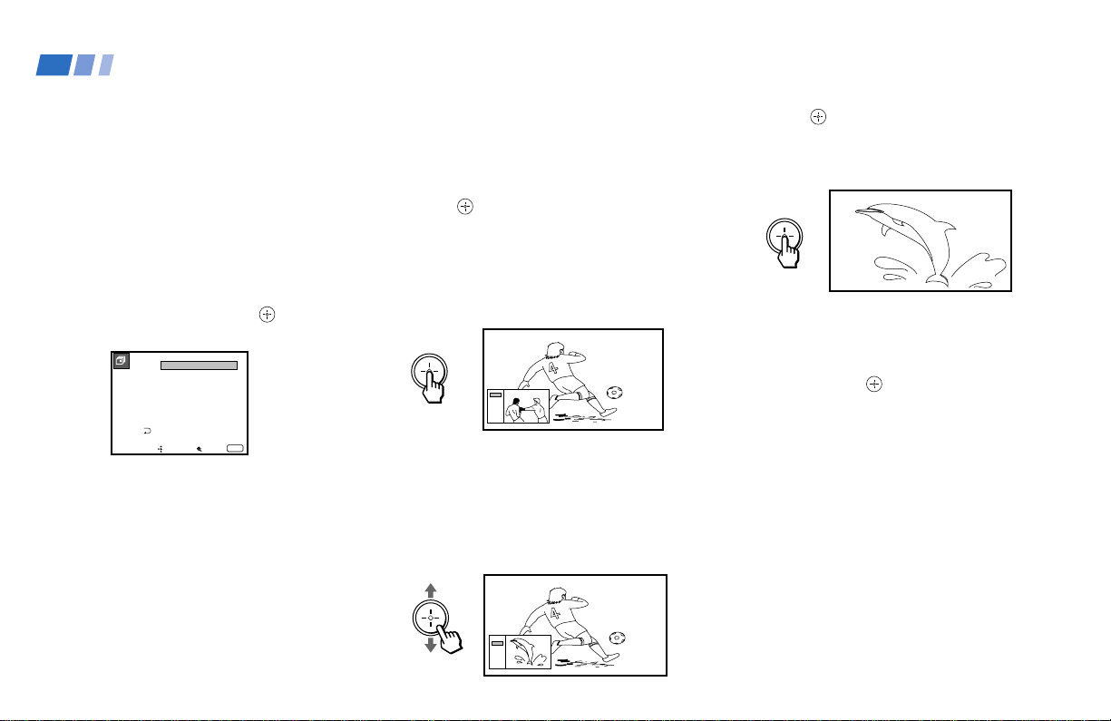
58
Changing FAVORITE CHANNEL
choices
You have the option of returning to the
FAVORITE CHANNEL screen to adjust any
of your favorite channel choices.
Simply proceed as described in “Setting
FAVORITE CHANNEL manually” (skip step
2 if MANUAL is already selected).
When you reach step 3, select the position
you want to change and press
. Move the
joystick up or down to select a new channel.
Press MENU when you are done.
Note:
• The FAVORITE CHANNEL feature is not
available for the picture input from AUX
or VIDEO 5 IN, and for digital TV
programs.
Using FAVORITE CHANNEL
You can use the FAVORITE CHANNEL
feature to directly select the channel you want
to watch.
1 Press once.
The favorite channel menu and a window
picture will be superimposed over the
current channel. The window picture
displays the channel selected from the
menu.
2 Move the joystick up or down to select the
channel that you wish to view from the
menu.
The picture of the selected channel will be
displayed in the window picture.
3 Press to select the channel.
The selected channel will be displayed for
normal viewing.
To cancel the favorite channel menu before
selecting a channel, move the joystick up or
down to select EXIT at the bottom of the
menu and press
.
FAVORITES
12 CNN
36 ESPN
50
60
70
80
90
120 MTV
EXIT
FAVORITES
12 CNN
36 ESPN
50
60
70
80
90
120 MTV
EXIT
Using Conventional TV Features (continued)
FAVORITE CHANNEL
Select a channel
2 .
3 .
4 .
5 .
6 .
7 .
8 .
1 .
2
10
22
30
40
52
125
SPTN
Move Select Exit
MENU
6
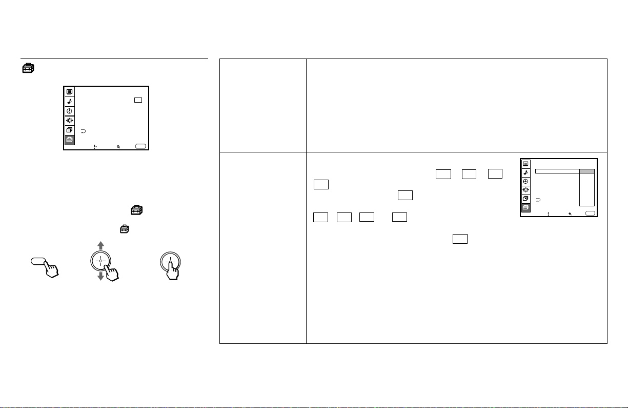
59
Move Select Exit
MENU
SET UP
PARENTAL CONTROL
CAPTION VISION:
SELECT OUT: MONITOR
LANGUAGE: ENGLISH
VIDEO LABEL
DIRECT PLAY
FREEZE MODE: NORMAL
CC1
PARENTAL
CONTROL
Blocks programs
unsuitable for children
CAPTION VISION
Television closed
caption display
Allows you to block TV programs that you feel are unsuitable for your children.
(see “Using the PARENTAL CONTROL Feature” on page 64 for details)
PARENTAL LOCK: Select ON to activate PARENTAL CONTROL. Programs
that match the selected ratings will be blocked.
Select OFF to turn off PARENTAL CONTROL. You can view all programs.
RATING: Select to choose from three Sony’s predetermined modes and one
custom rating mode (CHILD/YOUTH/YOUNG ADULT and CUSTOM).
CHANGE PASSWORD: Select to change the password.
Some programs are broadcast with Caption Vision.
To display Caption Vision, select CC 1, CC 2, CC 3,
CC 4, TEXT1, TEXT2, TEXT3 or TEXT4 from the
menu. Then press the CC button until Caption Vision
is displayed.
CC 1, CC 2, CC 3 or CC 4 displays a printed
version of the dialogue or sound effects of a
program. (The mode should be set to CC 1 for most
programs.) TEXT1, TEXT2, TEXT3, or TEXT4
displays network/station information presented using
either half or the whole screen.
Notes:
• Poor reception of conventional TV programs can cause errors in Caption
Vision and XDS.
Captions may appear with a white box or other errors instead of the intended
text.
• XDS, Caption Vision, and the status display cannot be used at the same time.
Using the SET UP Menu
For detailed information on using the remote
control to modify menu settings, refer to
“Learning Menu Selection” on page 46.
To select the SET UP menu:
Display / Highlight / Select
Notes:
• When you set SELECT OUT to TV OUT,
you cannot swap the main/right and
window/left pictures.
• The SELECT OUT signal is only available
when the projection TV is on.
MENU
(continued)
FREEZE MODE:NORNAL
SELECT OUT:MONITOR
LANGUAGE:ENGLISH
Move Select
Exit
MENU
SET UP
PARENTAL CONTROL
CAPTION VISION
VIDEO LABEL
DIRECT PLAY
TEXT1
TEXT2
TEXT3
TEXT4
CC1
CC2
CC3
CC4
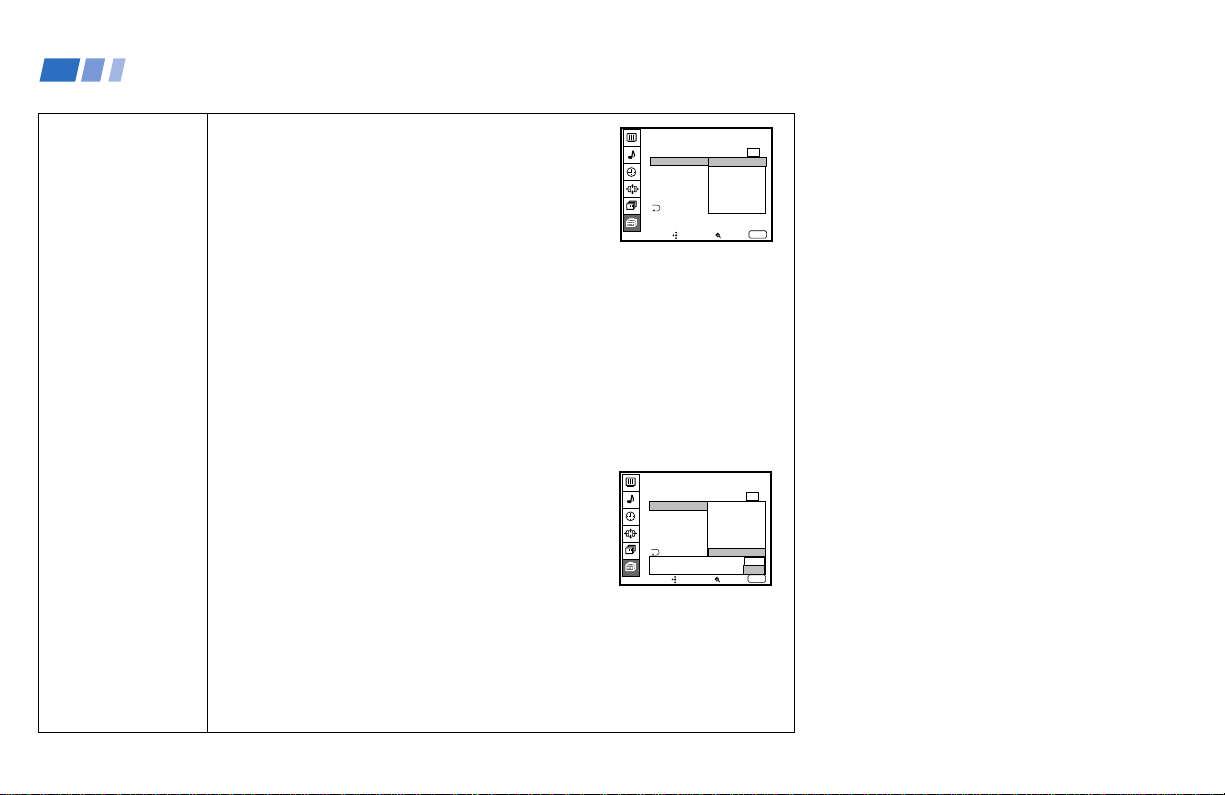
60
SELECT OUT
Output signal
selection from
SELECT OUT
You can select the desired output signal from the
SELECT OUT jacks on the upper panel at the rear.
MONITOR: Select to edit tapes while monitoring.
SELECTOUT outputs the picture displayed on the
screen.
Note:
• With this setting, the picture input from VIDEO 5
IN or digital TV programs is not output from
SELECT OUT.
VIDEO1–VIDEO4: Select to edit tapes while viewing an input image different
from that being recorded. SELECT OUT outputs the signal input to the
projection TV regardless of the displayed picture on the screen.
TV OUT: Select if you connect an AV receiver to VIDEO 1 IN. SELECT OUT
outputs the signal that the TV is tuned to, regardless of the displayed picture.
(see “Connecting an AV receiver” on page 17 for connection)
If you select TV OUT, the following pop-up menu appears.
Note:
• With this setting, digital TV signal is not output
from SELECT OUT.
Select YES only if you have connected an AV
receiver, with no other equipment, to your projection
TV. You can always select the signal from the
receiver by pressing TV/VIDEO once.
Note:
• If you select YES, you cannot view a digital TV program as SELECT OUT
does not output a digital TV signal to the receiver.
Select NO if you have connected multiple components to your projection TV.
You can select an input (VIDEO1 – VIDEO4) with the TV/VIDEO button.
FREEZE MODE:
Move Select
Exit
MENU
SET UP
PARENTAL CONTROL
CAPTION VISION:
LANGUAGE:
SELECT OUT:
VIDEO LABEL
DIRECT PLAY
CC1
VIDEO1
MONITOR
VIDEO2
VIDEO3
VIDEO4
TV OUT
Using Conventional TV Features (continued)
FREEZE MODE:
Move Select
Exit
MENU
SET UP
PARENTAL CONTROL
CAPTION VISION:
LANGUAGE:
SELECT OUT:
VIDEO LABEL
DIRECT PLAY
CC1
VIDEO1
MONITOR
VIDEO2
VIDEO3
VIDEO4
TV OUT
Set up using YES
only VIDEO1 input? NO
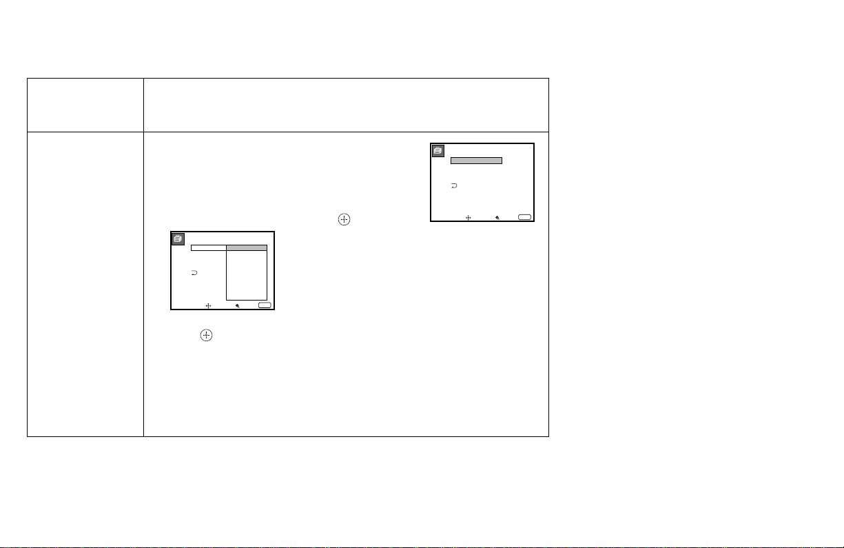
61
VIDEO LABEL
VIDEO1
VIDEO2
VIDEO3
VIDEO4
VIDEO1:
VIDEO2:
VIDEO3:
VIDEO4:
Move Select Exit
MENU
VIDEO LABEL
VIDEO1:
VIDEO2:
VIDEO3:
VIDEO4:
VIDEO1
VHS
8mm
BETA
LD
DBS
DVD
AV RECEIVER
SKIP
Move Select Exit
MENU
LANGUAGE
User’s preferred
language
VIDEO LABEL
Easy recognition of
connected
equipment
(e.g. DBS, VHS,
etc.).
Select from available languages (English or Spanish) to display all menus in
your language of choice.
This feature allows you to label each input mode so
that you can easily identify the connected equipment
(e.g. you can label VIDEO 1 IN as VHS).
With the VIDEO LABEL window open:
1 Move the joystick up or down to select the input
mode you want to label and press .
2 Move the joystick up or down to select the label and
press .
VIDEO LABEL Options:
VIDEO 1: VIDEO 1, VHS, 8mm, BETA, LD, DBS, DVD, AV RECEIVER,
SKIP
VIDEO 2–4: VIDEO 2–4, VHS, 8mm, BETA, LD, DBS, DVD, SKIP
If you select SKIP, your projection TV will skip this connection when you scan
through video sources using the TV/VIDEO button.
(continued)
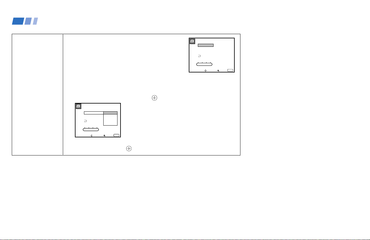
62
DIRECT PLAY
VIDEO1:
VIDEO2:
VIDEO3:
VIDEO4:
OFF
OFF
OFF
OFF
1 2 3 DVD/MDP
Move Select Exit
MENU
DIRECT PLAY
VIDEO1:
VIDEO2:
VIDEO3:
VIDEO4:
OFF
VTR1
VTR2
VTR3
DVD/MDP
1 2 3 DVD/MDP
Move Select Exit
MENU
DIRECT PLAY
Easy operation of a
connected VCR
This feature allows you to switch the input mode from
the TV to a Sony VCR (MDP or DVD) and start
playing by only pressing the ( (playback) button on
the remote control. You have to set the VTR 1/2/3/
DVD/MDP switch on the remote control (e.g., you
connect your VCR to the VIDEO 3 IN jacks and set
the VTR 1/2/3/DVD/MDP switch to VTR 3).
With the DIRECT PLAY window open:
1 Move the joystick up or down to select the input to which your video
equipment is connected, and press .
2 Move the joystick up or down to select the position of the VTR 1/2/3/DVD/
MDP switch, and press .
(continued)
Using Conventional TV Features (continued)
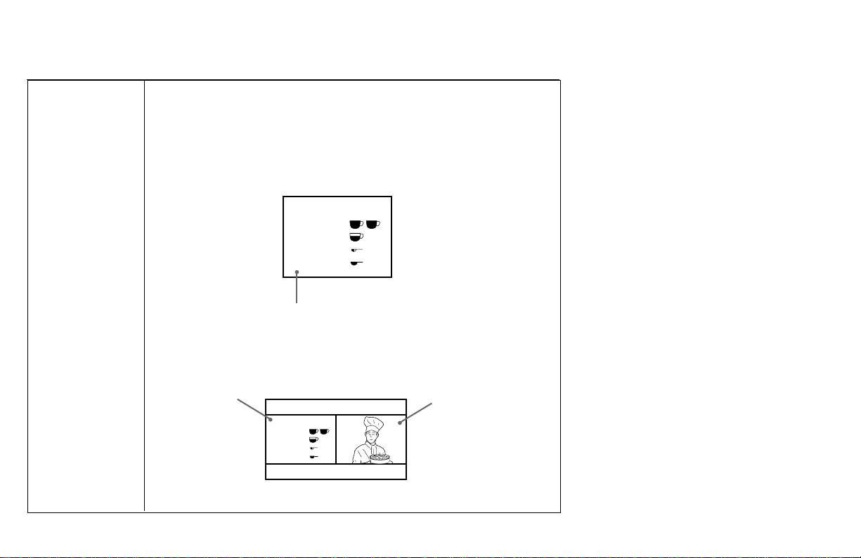
63
FREEZE MODE
Freeze picture
mode
Useful when you need to copy down information that appears on the TV’s
screen.
Note: The FREEZE MODE feature is not available for the inputs from VIDEO
5 IN and for digital TV programs.
NORMAL: Select to freeze the whole picture on the screen by pressing
FREEZE.
TWIN: Select to freeze the desired scene and display it on the left of the
screen while viewing the normal picture of the current channel on
the right by pressing FREEZE.
This mode is not available for PIP, P&P or CH INDEX screens.
Press FREEZE again or press (OFF) to display the normal picture.
Frozen picture
The current picture freezes.
Normal motion picture
Recipe
flour - - - - 2
sugar - - - 1/2
salt - - - - - 1/2
butter - - - 1
Recipe
flour - - - - 2
sugar - - - 1/2
salt - - - - - 1/2
butter - - - 1
66
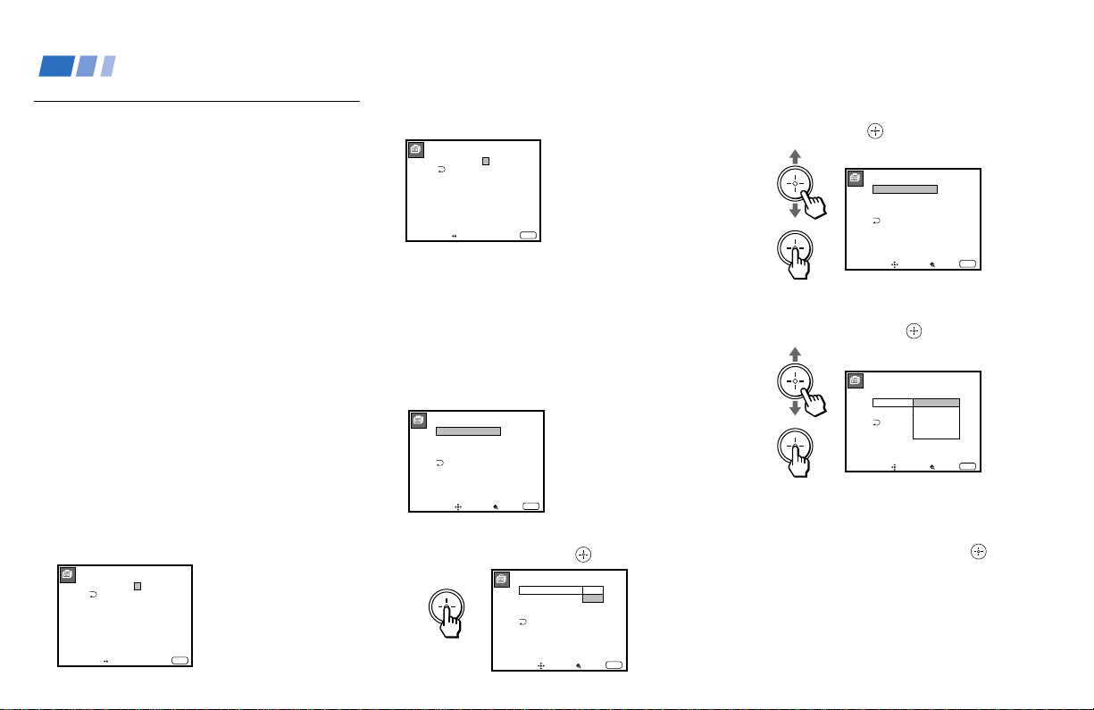
64
Using the PARENTAL
CONTROL Feature
TV programs and movies shown on TV are
given a rating signal based on one of two
rating systems. One is the Television Parental
Guidelines to rate television programs (TV
ratings), and the other is the Motion Picture
Association of America (MPAA) Guidelines
to rate movies including those shown on TV
(movie ratings).
To block programs you feel are unsuitable for
your children, you need to set the TV for
both rating systems. Sony’s predetermined
ratings are also available.
See pages 70 and 71 for a description of the
ratings.
Activating the PARENTAL
CONTROL Feature
First, set a password, then select your desired
rating from Sony’s predetermined ratings.
1 Select PARENTAL CONTROL from the
SET UP menu. (see page 59)
2 Enter a four digit password* using the 0–9
buttons.
3 To confirm the password, re-enter the
same password with the 0–9 buttons.
Your password is stored and the
PARENTAL CONTROL menu
automatically appears.
If you want to change the password, see
page 69.
4 Make sure that PARENTAL LOCK is
highlighted, and press .
5 Move the joystick up or down to select
ON, and press .
6 Move the joystick up or down to select
RATING, and press .
7 Move the joystick up or down to select a
desired rating (CHILD, YOUTH and
YOUNG ADULT), and press
.
If you want to select the ratings from
CUSTOM, go to step 4 of “Selecting a
Custom Rating” on page 66.
8 Press MENU to exit the menu.
PARENTAL LOCK:
RATING: CHILD
CHANGE PASSWORD
PARENTAL CONTROL
Move Select Exit
MENU
ON
OFF
PARENTAL CONTROL
PARENTAL LOCK:
RATING: CHILD
CHANGE PASSWORD
Move Select Exit
MENU
OFF
PARENTAL CONTROL
PARENTAL LOCK:
RATING: CHILD
CHANGE PASSWORD
Move Select Exit
MENU
ON
PARENTAL CONTROL
Move
Age up to 6
Select Exit
MENU
ONPARENTAL LOCK:
RATING:
CHANGE PASSWORD
CHILD
YOUTH
YOUNG ADULT
CUSTOM
Using Conventional TV Features (continued)
PARENTAL CONTROL
Move Exit
MENU
PASSWORD:
____
Use [0-9] to enter
new four digit
password
PARENTAL CONTROL
Move Exit
MENU
PASSWORD:
____
Confirm password
* Do not enter “4357”
corresponding to
“HELP” on the phone
number pad. (see page
69)
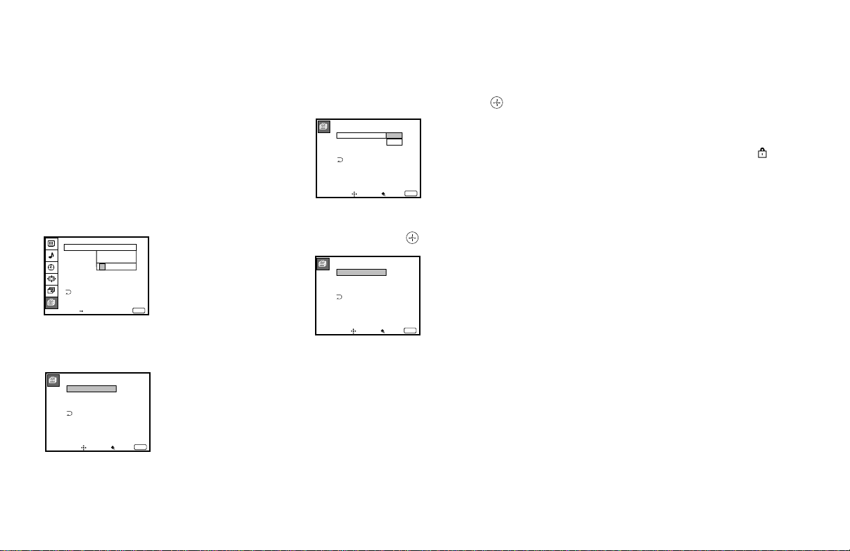
65
To deactivate the PARENTAL CONTROL
feature
If you set PARENTAL LOCK in the
PARENTAL CONTROL menu to OFF, the
PARENTAL CONTROL feature will not
work and you can view all TV programs and
movies shown on TV.
1 Select PARENTAL CONTROL from the
SET UP menu. (see page 59)
2 Enter your four digit password using the
0–9 buttons.
3 Move the joystick up or down to select
PARENTAL LOCK, and press
.
4 Move the joystick up or down to select
OFF, and press .
5 Press MENU to exit the menu.
PARENTAL CONTROL
PARENTAL LOCK:
RATING: CHILD
CHANGE PASSWORD
Move Select Exit
MENU
OFF
To unlock the PARENTAL CONTROL
feature temporarily
When you select a PARENTAL CONTROL
program, no sound or picture except for a
channel number will appear. The
indicator
is displayed. To view the program, follow the
steps below.
1 Press ENTER to display the “Password”
screen.
2 Enter your password using the 0–9
buttons. The PARENTAL CONTROL
feature will be canceled (PARENTAL
LOCK set to OFF) until you turn your
projection TV off.
PARENTAL CONTROL
PARENTAL LOCK:
RATING: CHILD
CHANGE PASSWORD
Move Select Exit
MENU
ON
PARENTAL LOCK:
RATING: CHILD
CHANGE PASSWORD
PARENTAL CONTROL
Move Select Exit
MENU
ON
OFF
Move Exit
MENU
SET UP
CAPTION VISION:
Use [0-9] to enter
password
SELECT OUT:
LANGUAGE:ENGLISH
VIDEO LABEL
DIRECT PLAY
ENTER
PASSWORD
_
FREEZE MODE:NORMAL
PARENTAL CONTROL
___
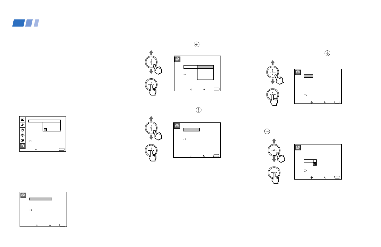
66
First, select a TV rating.
5 Move the joystick up or down to select
TV RATING, and press .
6 Move the joystick up or down to select
the TV rating to be blocked, and press
.
Selecting a Custom Rating
If you want to select the ratings to be blocked
from CUSTOM once you have activated the
PARENTAL CONTROL feature (page 64),
follow the procedure below.
For a detailed description of each rating, see
“What the Ratings Mean” on pages 70 and
71.
1 Select PARENTAL CONTROL from the
SET UP menu. (see page 59)
2 Enter your four digit password using the
0–9 buttons.
The PARENTAL CONTROL menu
appears.
3 Move the joystick up or down to select
RATING, and press
.
4 Move the joystick up or down to select
CUSTOM, and press .
PARENTAL CONTROL
PARENTAL LOCK:
RATING: CHILD
CHANGE PASSWORD
Move Select Exit
MENU
ON
PARENTAL CONTROL
Move
Age up to 6
Select Exit
MENU
ONPARENTAL LOCK:
RATING:
CHANGE PASSWORD
CHILD
YOUTH
YOUNG ADULT
CUSTOM
CUSTOM RATING
Move
Select category
Select Exit
MENU
TV RATING
MOVIE RATING
UNRATED: VIEW ALL
TV RATING
Move
Select rating
Select Exit
MENU
TV–Y
TV–Y7
TV–G
TV–PG
TV–14
TV–MA
_
_ :FV _
_
_ :D _ L _ S _ V _
_ :D _ L _ S _ V _
_ : L _ S _ V _
TV RATING
Move
Allow rating
Select Exit
MENU
TV–Y
TV–Y7
TV–G
TV–PG
TV–14
TV–MA
_
_ :FV _
_
:D _ L _ S _ V _
_ :D _ L _ S _ V _
: L _ S _ V _
_
Using Conventional TV Features (continued)
Move Exit
MENU
SET UP
CAPTION VISION:
Use [0-9] to enter
password
SELECT OUT:
LANGUAGE:ENGLISH
VIDEO LABEL
DIRECT PLAY
ENTER
PASSWORD
_
FREEZE MODE:NORMAL
PARENTAL CONTROL
___
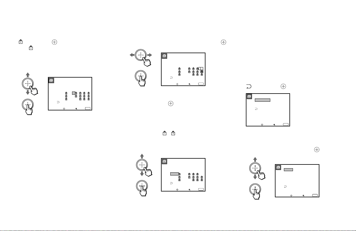
67
10
Repeat steps 8 and 9 for other extenders.
All programs that match the ratings you
select and higher, except for the
extenders that were canceled, will be
blocked.
11
After setting of the TV rating is complete,
move the joystick up or down to select
, and press .
Second, select a movie rating.
12
Move the joystick up or down to select
MOVIE RATING, and press
.
7 Move the joystick up or down to select
, and press .
The indicator automatically appears
beside the selected rating and all “higher”
ratings, indicating that the programs that
match the ratings will be blocked.
Some ratings have additional content
ratings called “extenders.” The extenders
are defined as follows: D (sexually
suggestive Dialog), FV (Fantasy
Violence), L (coarse Language), S (Sexual
situations) and V (Violence). By setting
the extenders, you can define additional
viewing limits. For more details of
extenders, see page 71.
All of the extenders included in the
selected ratings will be blocked. If you
wish to allow any of them to be viewed,
go to step 8.
8 Move the joystick left or right to select
the extender to be viewed, and press
.
9 Move the joystick up or down to select
“–,” and press .
“–” appears beside the selected extender,
indicating that the programs that match
the extender can be viewed.
If you select
, is displayed to show
that the programs that match the
extender will be blocked again.
TV RATING
Move
Block content
Select Exit
MENU
TV–Y
TV–Y7
TV–G
TV–PG
TV–14
TV–MA
_
_ :FV _
_
– :D – L – S – V –
– :D – L – S – V –
– : L – S – V
TV RATING
Move
Select category
Select Exit
MENU
TV–Y
TV–Y7
TV–G
TV–PG
TV–14
TV–MA
_
_ :FV _
_
– :D – L – S – V _
– :D – L – S – V –
– : L – S – V
TV RATING
Move
Select category
Select Exit
MENU
TV–Y
TV–Y7
TV–G
TV–PG
TV–14
TV–MA
_
_ :FV _
_
– :D – L – S – V –
– :D – L – S – V –
– : L – S – V
CUSTOM RATING
Move
Select category
Select Exit
MENU
TV RATING
MOVIE RATING
UNRATED: VIEW ALL
MOVIE RATING
Move
Select rating
Select Exit
MENU
G
PG
PG–13
R
NC–17
X
–
–
–
–
–
–
(continued)
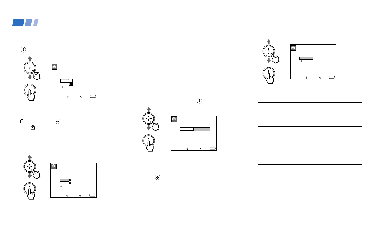
68
13
Move the joystick up or down to select
the movie rating to be blocked, and press
.
14
Move the joystick up or down to select
, and press .
The
indicator automatically appears
beside the selected rating and all “higher”
ratings, indicating that the programs that
match the ratings will be blocked.
15
Press MENU to exit the menu.
To block TV programs and/or movies
for which a rating signal is not given
(NR and N/A)
For a description of the NR and N/A ratings,
see pages 70 and 71.
1 Perform steps 1–4 of “Selecting a Custom
Rating” on page 66.
2 Move the joystick up or down to select
UNRATED, and press
.
3 Move the joystick up or down to select
the type of programs to be blocked, and
press .
MOVIE RATING
Move
Select rating
Select Exit
MENU
G
PG
PG–13
R
NC–17
X
–
–
–
–
–
–
4 Press MENU to exit the menu.
MOVIE RATING
Move
Block rating
Select Exit
MENU
G
PG
PG–13
R
NC–17
X
–
–
–
–
–
–
CUSTOM RATING
Move
No block
Select Exit
MENU
TV RATING
MOVIE RATING
UNRATED: VIEW ALL
TV
MOVIE
BOTH
Using Conventional TV Features (continued)
CUSTOM RATING
Move Select Exit
MENU
TV RATING
MOVIE RATING
UNRATED: BOTH
Block all unrated
programming
To block ...
No program
(to view any unrated TV
program and movie)
Unrated TV programs
Unrated movies
Unrated TV programs and
movies
Select ...
VIEW ALL
TV
MOVIE
BOTH
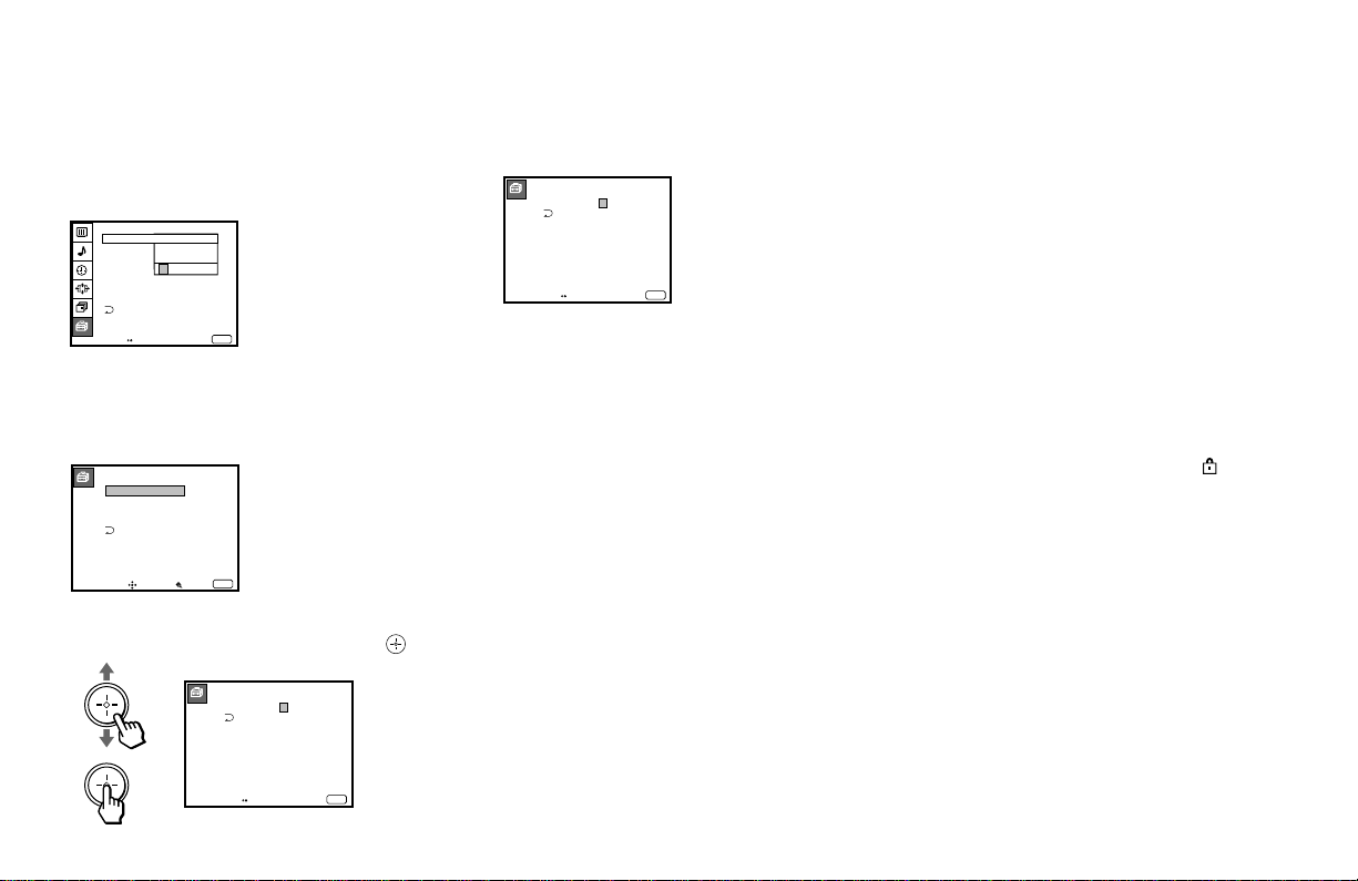
69
Changing the Password
1 Select PARENTAL CONTROL from the
SET UP menu. (see page 59)
2 Enter your four digit password using the
0–9 buttons.
The PARENTAL CONTROL menu
appears.
3 Move the joystick up or down to select
CHANGE PASSWORD, and press
.
PARENTAL CONTROL
PARENTAL LOCK:
RATING: CHILD
CHANGE PASSWORD
Move Select Exit
MENU
ON
4 Enter a new four digit password using
the 0–9 buttons.
5 Enter the password set in step 4 again to
confirm.
If you entered it incorrectly, “Password
incorrect” appears.
Re-enter the correct password.
6 Press MENU to exit the menu.
If you have forgotten your password
In step 2 of “Changing the Password” above,
enter the master password “4357”
(corresponding to “HELP” on the phone
number pad). You can then store a new
password.
Notes
• If you entered “4357” as your password
the first time, you cannot store a new
password. (see step 2 of “Activating the
PARENTAL CONTROL Feature” on page
64)
• When you select a PARENTAL
CONTROL program and the
indicator
is displayed on the screen, you cannot
view that program even if you enter
“4357.” (see “To unlock the PARENTAL
CONTROL feature temporarily” on page
65)
CHANGE PASSWORD
Move Exit
MENU
PASSWORD:
____
Use [0-9] to enter
new four digit
password
CHANGE PASSWORD
Move Exit
MENU
PASSWORD:
____
Confirm password
Move Exit
MENU
SET UP
CAPTION VISION:
Use [0-9] to enter
password
SELECT OUT:
LANGUAGE:ENGLISH
VIDEO LABEL
DIRECT PLAY
ENTER
PASSWORD
_
FREEZE MODE:NORMAL
PARENTAL CONTROL
___

70
NC-17 or X (No One 17 Or Under
Admitted.): This is a film that most parents
would consider not suitable for children
aged 17 and under. There may be violence,
sex, abberrational behavior, drug abuse or
other elements of concern.
NR (Not Rated): This is a film that a
producer has not rated, intending to have his
film widely released.
N/A (Not Applicable): This is a film that a
producer considers outside the scope of the
MPAA ratings.
Note:
• NR and N/A ratings are shown together
as UNRATED in the menu.
Movie ratings
Movie ratings are for movies (including those
shown on TV) rated according to the Motion
Picture Association of America (MPAA)
Guidelines.
G (General Audiences—All Ages
Admitted): In G-rated films no strong words
are used, the violence is at a minimum,
nudity and sex scenes are not present, nor is
there any drug use.
PG (Parental Guidance Suggested. Some
Material May Not Be Suitable For
Children): This is a film which may need to
be monitored first by parents.
PG-13 (Parents Strongly Cautioned. Some
Material May Be Inappropriate For Children
Under 13): Parents are alerted to be very
careful about the attendance of their under-
teenage children when viewing.
R (Restricted, Under 17 Require
Accompanying Parent Or Adult Guardian):
This film includes hard language, tough
violence, nudity, drug abuse or other
elements of concern.
Using Conventional TV Features (continued)
What the Ratings Mean
Sony’s predetermined ratings
These are original ratings that Sony
predetermined according to the viewer’s age.
Each rating allows you to view the certain
programs, as follows.
See pages 70 and 71 for a description of TV
and movie ratings.
CHILD: Suitable for children under the age of
6.
Viewable movie ratings: G, NR, and N/A
Viewable TV ratings: TV-Y, TV-G, and TV-
NR
YOUTH: Suitable for children aged 7 and
older.
Viewable movie ratings: G, PG, NR, and
N/A
Viewable TV ratings: TV-Y, TV-Y7, TV-G,
TV-PG, and TV-NR
YOUNG ADULT: Suitable for children aged
14 and older.
Viewable movie ratings: G, PG, PG-13, NR,
and N/A
Viewable TV ratings: TV-Y, TV-Y7, TV-G,
TV-PG, TV-14, and TV-NR

71
Note:
TV-Y7, TV-PG, TV-14 and TV-MA ratings
have additional content ratings called
“extenders” to define additional viewing
limits. The extenders are defined as follows:
D (sexually suggestive Dialog): Programs
containing suggestive dialog, or sexual
innuendo
FV (Fantasy Violence): Programs containing
cartoon violence occurring in TV-Y7
programs only
L (coarse Language): Programs containing
coarse language
S (Sexual situations): Programs containing
sexual content
V (Violence): Programs containing violence
There may be some profanity, violence or
brief nudity in these programs.
TV ratings
TV ratings are for TV programs rated
according to the Television Parental
Guidelines.
TV-Y (All Children): This program is
designed for young children aged 2–6 and is
appropriate for all children.
TV-Y7 (Directed to Older Children): This
program is designed for children aged 7 and
above. Themes and elements in this program
may include mild fantasy violence or
slapstick violence, or may frighten children
under the age of 7.
TV-G (General Audience): Most parents
would find this program suitable for all ages.
It contains little or no violence, no strong
language and little or no sexual dialog or
situations.
TV-PG (Parental Guidance Suggested):
This program contains some material that
parents may find unsuitable for younger
children.
TV-14 (Parents Strongly Cautioned): This
program contains some material that many
parents would find unsuitable for children
under the age of 14.
TV-MA (Mature Audience Only): This
program is specifically designed to be
viewed by adults and therefore may be
unsuitable for children under the age of 17.
TV-NR (Not Rated/Unrated): This is a
program broadcast without any rating, such
as news, news flashes or sports.
This setting is shown as UNRATED in the
menu.
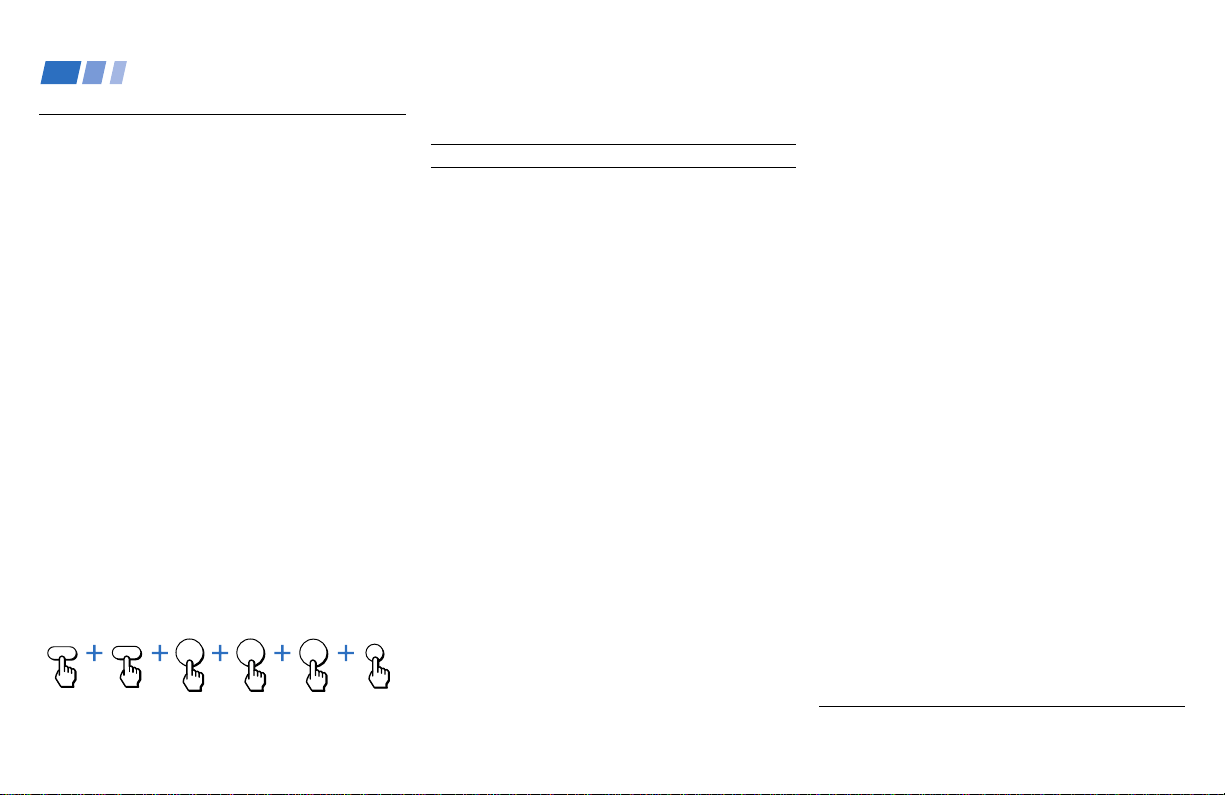
72
Setting the Manufacturer's
Code
You can use the supplied remote control to
operate Sony or non-Sony video equipment
that has an infrared sensor.
1 Set the VTR 1/2/3/DVD/MDP switch to
the input through which you would like
to access your video equipment.
The following Sony equipment is preset to
each input as shown below:
VTR1 (303) Beta, ED Beta VCRs
VTR2 (302) 8 mm VCR
VTR3 (301) VHS VCR
DVD/MDP (751) DVD Player
2 Press CODE SET, DVD/VTR (FUNCTION),
and the 0-9 buttons to enter the
manufacturer’s code number (see the
following chart), then press ENTER.
For example, to operate a Sony 8mm VCR:
If the remote control doesn’t work
• See page 74.
Operating Video Equipment
VCR manufacturer code numbers
Manufacturer Code
Sony 301, 302, 303
Aiwa 338
Admiral (M. Ward) 327
Audio Dynamic 314, 337
Bell & Howell (M. Ward) 330, 343
Broksonic 319, 317
Canon 309, 308
Citizen 332
Craig 315, 302, 332
Criterion 315
Curtis Mathis 304, 338, 309
Daewoo 341, 312, 309
DBX 314, 336, 337
Dimensia 304
Emerson 319, 320, 316, 317, 318, 341
Fisher 330, 334, 335, 333
Funai 338
General Electric 329, 304, 309
Go Video 340, 339, 322
Goldstar 332
Hitachi 306, 304, 305, 338
Instant Replay 309, 308
JC Penney 309, 305, 304, 330, 314, 336, 337
JVC 314, 336, 337
Kenwood 314, 336, 332, 337
LXI (Sears) 332, 305, 333, 334, 330, 335, 338
Magnavox 308, 309, 310
Marantz 314, 336, 337
Marta 332
Memorex 309, 335
Minolta 305, 304
Mitsubishi/MGA 323, 324, 325, 326
Multitech 325, 338, 321
NEC 314, 336, 337
Olympic 309, 308
Optimus 327
Panasonic 308, 309, 306, 307
Pentax 305, 304
Philco 308, 309
Philips 308, 309, 310
Pioneer 308
Quasar 308, 309, 306
RCA/PROSCAN 304, 305, 308, 309, 311,
329, 312, 313, 310
Realistic 309, 330, 328, 335, 324, 338
Sansui 314
Singer 315
Samsung 322, 313, 321
Sanyo 330, 335
Scott 312, 313, 321, 335, 323, 324, 325, 326
Sharp 327, 328
Shintom 315
Signature 2000 (M. Ward) 338, 327
Sylvania 308, 309, 338, 310
Symphonic 338
SV2000 338
Tashiro 332
Tatung 314, 336, 337
Teac 314, 336, 338, 337
Technics 309, 308
Teknica 342, 338
Toshiba 312, 311
Wards 327, 328, 335, 331, 332
XR-1000 315
Yamaha 330, 314, 336, 337
Zenith 331
2
3
0
CODE SET
ENTER
DVD/VTR
FUNCTION

73
MDP manufacturer code numbers
Manufacturer Code
Sony 701
Panasonic 704
Pioneer 702
DVD Player manufacturer code
numbers
Manufacturer Code
Sony 751
Panasonic 753
Pioneer 752
RCA 755
Toshiba 754
Tips
z
• In some rare cases, you may not be able to operate your
non-Sony video equipment with the supplied remote
control. In this case, please use the equipment's own
remote control.
• When you remove the batteries, the code number may
revert to the factory setting.
To operate video equipment
1 Set the VTR1/2/3/DVD/MDP switch to
the input through which you would like to
access your video equipment.
2 Press DVD/VTR (FUNCTION).
3 Use the VCR/DVD/MDP buttons
indicated in the following tables.
Operating an MDP using the remote control
To turn On/Off
To play
To stop
To pause
Operating a VCR using the remote control
To turn On/Off
To select a channel
To change channels
To record
To play
To stop
To fast forward
To rewind the tape
To pause
To search the
picture forward or
backward
To change input
mode
Press DVD/VTR (POWER).
[Green Button]
Press the 0 – 9 buttons.
Press CH +/–.
Press (REC) while
pressing (lower).
Press (.
Press p.
Press ).
Press 0.
Press P. Press again to
resume normal playback.
Press ) or 0 during
playback. Release to
resume normal playback.
Press TV/VTR.
Press DVD/VTR (POWER).
[Green Button]
Press (.
Press p.
Press P. Press again to
resume normal playback.
Operating a DVD Player using the remote
control
To turn On/Off
To play
To stop
To pause
To step through
different tracks of
an audio disc
To step through
different chapters
of a video disc
To display the Title
menu
To display the DVD
menu
To select tracks
directly
To display the
menu (Set up)
Press DVD/VTR (POWER).
[Green Button]
Press (.
Press p.
Press P. Press again to
resume normal playback.
Press ) to step forward or
0 to step backward.
Press CH+ to step forward or
CH– to step backward.
Press TITLE.
Press DVD MENU.
Press 0-9 buttons.
Press MENU.
Press ) or 0 during
playback. Release to resume
normal playback.
Press CH +/–.
To search the picture
forward or backward
To search a chapter
forward or backward
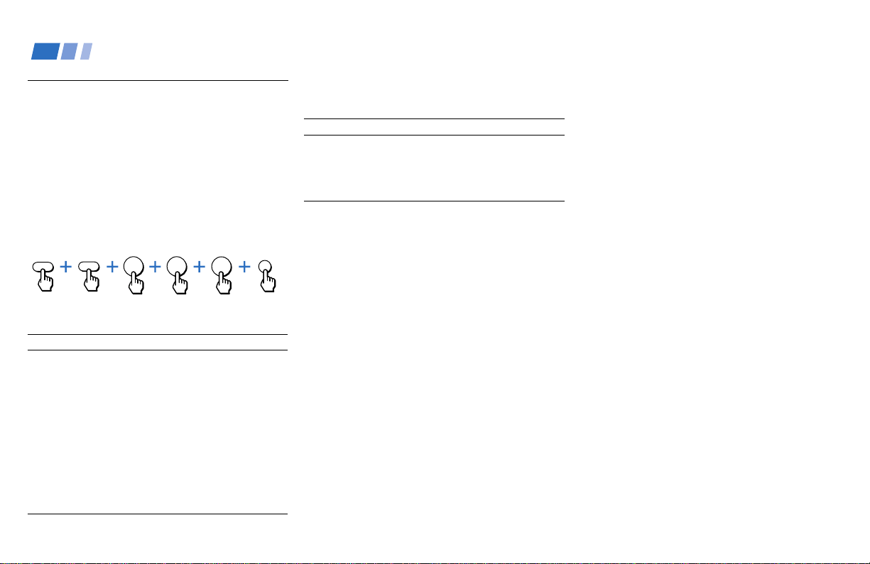
74
Manufacturer
Gemini
Hamlin/Regal
Jerrold/G. I.
Macom
Magnavox
Oak
Panasonic
Philips
Pioneer
Samsung
Scientific Atlanta
Tocom
Zenith
Operating a Cable Box or DBS Receiver
Code number
801 (preset code for
remote control)
802
802
Manufacturer code numbers
(DBS receiver)
Manufacturer
Sony
General Electric
RCA/PROSCAN
To operate the cable box or DBS
receiver
1 Press DBS/CABLE (POWER) (green
labeled button) to turn on/off the cable
box or DBS receiver.
2 Press DBS/CABLE (FUNCTION).
3 For other operations, refer to the
operating instructions that come with the
equipment.
If the remote control doesn’t work
• Try repeating the set up procedures using
the other codes listed for your equipment.
To operate the projection TV
Press TV (FUNCTION). Then use the
projection TV control buttons to control the
projection TV.
Tips z
• If more than one code number is listed, try entering
them one by one until you come to the correct code for
your equipment.
• If you enter a new code number, the code number you
previously entered at that setting is erased.
• In some rare cases, you may not be able to operate
your equipment with the supplied remote control. In
this case, use the equipment’s own remote control
unit.
• Whenever you remove the batteries — to replace
them, for example — if too much time is taken, the
code numbers may revert to the factory setting and
must be reset.
1
8
0
CODE SET
ENTER
DBS/CABLE
FUNCTION
Setting the Manufacturer's
Code
You can program the supplied remote
control to operate a cable box or DBS
receiver.
Press CODE SET, DBS/CABLE
(FUNCTION), and the 0-9 buttons to enter
the manufacturer’s code number (see the
following chart), then press ENTER.
For example, to operate a Sony DBS receiver:
Manufacturer code numbers
(cable box)
Code
233
222, 223, 224, 225, 226
201, 202, 203, 204, 205,
222, 206, 207, 208, 218
230, 231, 232
234
227, 228, 229
219, 220, 221
236, 237, 238, 239, 240, 241
214, 215
235
209, 210, 211
216, 217
212, 213
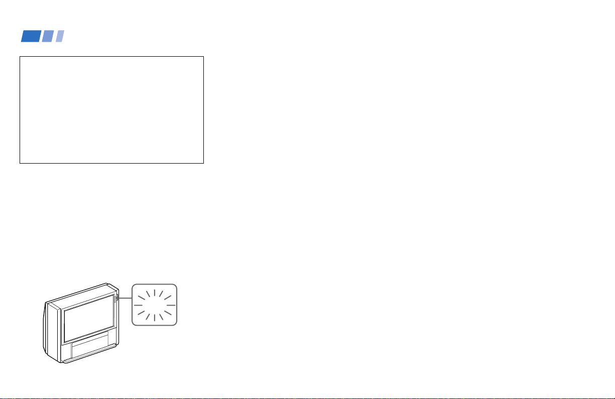
75
Troubleshooting
If, after reading the following instructions, you
have additional questions related to the use of
your Sony projection TV, please call one of the
following numbers (English only).
Customers in the continental United States
contact the Direct Response Center at:
1-800-222-SONY (7669)
Customers in Canada contact the
Customer Relations Center at:
(416) 499-SONY (7669)
1 Count how many times the TIMER/STAND
BY indicator flashes in total. It flashes twice
at 3 seconds’ intervals. If, for example, the
indicator flashes twice, stops flashing for 3
seconds, and flashes twice again, that
counts as twice.
2 Press POWER on the projection TV to turn it
off, then inform qualified Sony personnel or
the above Direct Response Center of the
number of flashes.
No picture (screen not lit), no sound
• Make sure the power cord is plugged in.
• Operate with the buttons on both the
projection TV and the remote control.
• Check to see if the TV/VIDEO setting is
correct: when watching TV, set to TV, and
when watching video tapes, set to VIDEO 1,
2, 3, 4 or 5.
• Try another channel.
It could be station
trouble.
• Perform AUTO SET UP again using “Auto
Program” for digital channels, or using the
SET UP button for conventional TV channels
to return to the factory preset condition. (see
“To perform AUTO SET UP again” on page
26)
• The PARENTAL CONTROL feature is
activated. (see “To unlock the PARENTAL
CONTROL feature temporarily” on page 65)
The picture turns off and the TIMER/STAND
BY indicator on the front panel flashes (self-
diagnosis function)
• The projection TV is equipped with a self-
diagnosis function. If there is a problem with
your projection TV, the TIMER/STAND BY
indicator on the front panel will flash
repeatedly. Counting the number of flashes
helps you inform qualified Sony personnel of
the projection TV’s condition.
Remote control does not operate
• Batteries could be weak. Replace the
batteries.
• Press TV (FUNCTION) when operating your
projection TV.
• Make sure the projection TV’s power cord is
connected securely to the wall outlet.
• Locate the projection TV at least 3-4 feet
away from fluorescent lights.
• Check the S-Link connection. (see “Using
the S-Link/CONTROL S Function” on page
20)
• Check the polarity of the batteries.
Dark, poor or no picture (screen lit), good
sound
• Adjust PICTURE in the VIDEO menu.
(see “PICTURE” on page 47)
• Adjust BRIGHTNESS in the VIDEO menu.
(see “BRIGHTNESS” on page 47)
• Check antenna/cable connections.
• Perform AUTO SET UP again using “Auto
Program” for digital channels, or using the
SET UP button for conventional TV channels
to return to the factory preset condition. (see
“To perform AUTO SET UP again” on page
26)
• Adjust the convergence again using the AUTO
FOCUS button. (see “Adjusting the
Convergence Automatically (AUTO FOCUS)
on page 27”)
TIMER/
STAND BY
(continued)

76
Good picture, no sound
• Press MUTING so that “MUTING” disappears
from the screen.
(see “MUTING” on pages 29, 37)
• Check the MTS setting in the AUDIO menu.
(see “MTS” on page 49)
• Make sure SPEAKER is set to ALL ON or L/R
OFF in the AUDIO menu. (see “SPEAKER” on
page 49)
• Perform AUTO SET UP again using “Auto
Program” for digital channels, or using the
SET UP button for conventional TV channels
to return to the factory preset condition. (see
“To perform AUTO SET UP again” on page
26)
No picture on a digital channel
• Switch to a different digital channel.
Cannot receive digital channels
• Press DTV ANT on the remote control so
that the TV (FUNCTION) indicator lights up
in green momentarily.
•
Make sure that VHF/UHF antenna is
connected to both VHF/UHF IN and VHF/
UHF (DTV) IN on the projection TV.
You cannot receive digital channels unless
you connect an analog terrestrial antenna.
This is true even if you normally receive your
programming through cable or satellite.
•
Use “DTV Auto Add” in the Channel Setup
menu to add receivable DTV channels that
are not presently in DTV memory.
• Make sure that the DTV I/O cable is
connected to both the lower and upper
panels at the rear of the projection TV.
•
Check your local listings to find out if you
can receive digital broadcasts in your area.
Unable to select a digital channel
•
Use “DTV Auto Add” in the “Channel Setup”
menu to add receivable DTV channels that
are not presently in DTV memory.
Cannot receive conventional TV channels
• Press TV ANT on the remote control so that
the TV (FUNCTION) indicator lights up in
red momentarily.
Cannot receive upper channels (UHF) when
using an antenna
• Make sure CABLE is OFF in the CHANNEL
SET UP menu. (see “CABLE” on page 54)
• Use AUTO PROGRAM to add receivable
channels that are not presently in the TV’s
memory. (see “AUTO PROGRAM” on page
54)
No color
• Adjust the COLOR in the VIDEO menu. (see
“COLOR” on page 47)
• Black and white programs cannot be seen in
color.
• Perform AUTO SET UP again using “Auto
Program” for digital channels, or using the
SET UP button for conventional TV channels
to return to the factory preset condition. (see
“To perform AUTO SET UP again” on page
26)
Only snow and noise appear on the screen
• Check the CABLE setting in the CHANNEL
SET UP menu. (see “CABLE” on page 54)
• Check the antenna/cable connections.
• Make sure the channel is broadcasting
programs.
• Press TV ANT to change the input mode.
(see “TV ANT” on page 36)
Dotted lines or stripes
• Adjust the antenna.
• Keep the projection TV away from noise
sources such as cars, neon signs or hair-
dryers.
Troubleshooting (continued)

77
Noisy picture (when DRC is set to HIGH in
the VIDEO menu)
•
Soften the sharpness using SHARPNESS in
the VIDEO menu.
TV is fixed to one channel
• Use AUTO PROGRAM to add receivable
channels that are not presently in
conventional TV’s memory. (see “AUTO
PROGRAM” on page 54)
• Try turning CHANNEL FIX off.
(see “CHANNEL FIX” on page 56)
Double images or ghosts
• Use a highly directional outdoor antenna or a
cable (when the problem is caused by
reflections from nearby mountains or tall
buildings).
Cannot operate the menu
• If the item you want to choose appears in
gray, you cannot select it.
•
Press the projection TV’s power
button off
and on again.
Cannot receive any channels when using
cable TV
• Make sure CABLE is ON in the CHANNEL
SET UP menu. (see “CABLE” on page 54)
• Use AUTO PROGRAM to add receivable
channels that are not presently in the TV’s
memory. (see “AUTO PROGRAM” on page
54)
Cannot gain enough volume when using a
cable box
• Increase the volume at the cable box. Then
press TV (FUNCTION) and adjust the
projection TV’s volume.
Projection TV malfunctions when using the S-
Link function
• Make sure the projection TV’s power cord is
connected securely to the wall outlet.
• Check the S-Link connection. (see “Using the
S-Link/CONTROL S Function” on page 20)
CHANNEL INDEX does not display all
available channels
• Make sure CABLE is ON in the CHANNEL
SET UP menu. (see “CABLE” on page 54)
• Use AUTO PROGRAM to add receivable
channels that are not presently in the TV’s
memory. (see “AUTO PROGRAM” on page
54)
FAVORITE CHANNEL does not display your
choices
• Verify that FAVORITE CHANNEL is set to
MANUAL in the CHANNEL SET UP menu.
(see “Setting FAVORITE CHANNEL manually”
on page 57)
Some video sources do not appear when you
press TV/VIDEO
• Ensure that VIDEO LABEL is not set to SKIP.
(see “VIDEO LABEL” on page 61)
Recording through SELECT OUT does not
function properly when recording in PIP or
P&P mode
• SELECT OUT will not record both images in
PIP or P&P. Only the main picture will be
recorded.
• If you are recording the main picture and you
switch to the sound of the sub picture using
the AUDIO button, the main picture will be
recorded with sound from the other program.
Cannot play shooting games
•
Some shooting games which involve pointing
a light beam at the TV screen with an
electronic gun or rifle cannot be used with
this projection TV. For details, see the
instruction manual supplied with the video
game software.
The picture blurs
• Press AUTO FOCUS on the projection TV.
(see “Adjusting the Convergence
Automatically (AUTO FOCUS)” on page 27)
Convergence is not adjusted correctly even
though you performed AUTO FOCUS
• Press AUTO FOCUS on the projection TV
again. (see “Adjusting the Convergence
Automatically (AUTO FOCUS)” on page 27)

78
Projection system
3 picture tubes, 3 lenses, horizontal in-line system
Picture tube
7-inch high-brightness monochrome tubes (6.3 raster
size), with optical coupling and liquid cooling
system
Projection lenses
High performance, large diameter hybrid lens F1.05
Television system
American TV standard
Channel coverage
DTV: 2–69/VHF: 2–13/UHF: 14 –69/CATV: 1 – 125
Antenna
75 ohm external terminal for VHF/UHF
Screen size (measured diagonally)
65 inches
Inputs/outputs on the upper panel
VIDEO 1/3 IN
VIDEO 2 INPUT
S VIDEO IN (4-pin mini DIN):
Y: 1 Vp-p, 75-ohms unbalanced, sync negative
C: 0.286 Vp-p (Burst signal), 75 ohms
VIDEO (phono jack): 1 Vp-p, 75-ohms unbalanced,
sync negative
AUDIO (phono jacks): 500 mVrms (100% modulation),
Impedance: 47 kilohms
VIDEO 4 IN
S VIDEO IN (4-pin mini DIN):
Y: 1 Vp-p, 75-ohms unbalanced, sync negative
C: 0.286 Vp-p (Burst signal), 75 ohms
VIDEO (phono jack): 1 Vp-p, 75-ohms unbalanced,
sync negative
AUDIO (phono jacks): 500 mVrms (100% modulation),
Impedance: 47 kilohms
Y: 1 Vp-p, 75 ohms, sync negative
P
B: 0.7 Vp-p, 75 ohms
P
R: 0.7 Vp-p, 75 ohms
Specifications
VIDEO 5 (HD) IN: Maximum scanning rate 1080i
Y: 1 Vp-p, 75 ohms, negative or tri-level sync
PB: 0.7 Vp-p, 75 ohms
P
R: 0.7 Vp-p, 75 ohms
or
G: 0.7 Vp-p
B: 0.7 Vp-p
R: 0.7 Vp-p
HD: 0.5–5 Vp-p, 2.2 kilohms
VD: 0.6–5 Vp-p, 2.2 kilohms
Note:
The VIDEO 5 (HD) IN jacks are not compatible with a
computer’s 5BNC (R/G/B/HD/VD) video output
connectors.
AUDIO (phono jacks): 500 mVrms (100% modulation),
Impedance: 47 kilohms
SELECT OUT
VIDEO (phono jack): 1 Vp-p, 75-ohms unbalanced,
sync negative
AUDIO (phono jacks): 470 mVrms (100% modulation),
Impedance: 4.7 kilohms
AUDIO (VAR) OUT (phono jacks): 950 mVrms (100%
modulation)
AUDIO (FIX) OUT (phono jacks): 500 mVrms (100%
modulation)
Inputs/outputs on the lower pznel
VIDEO 1/2 OUT
S VIDEO OUT (4-pin mini DIN):
Y: 1 Vp-p, 75-ohms unbalanced, sync negative
C: 0.286 Vp-p (Burst signal), 75 ohms
VIDEO (phono jacks): 1 Vp-p, 75-ohms unbalanced,
sync negative
AUDIO (phono jacks): 470 mVrms (100% modulation),
Impedance: 4.7 kilohms
VIDEO 3 OUT
Analog RGB/Component (phono jacks)
Y: 1.0 Vp-p, 75 ohms, sync negative
P
B: 0.7 Vp-p, 75 ohms
P
R: 0.7 Vp-p, 75 ohms
VIDEO 4 OUT
R/G/B: 0.7 Vp-p, 75 ohms
HD SYNC: 3 Vp-p, positive
VD SYNC: 3 Vp-p, positive
DOLBY DIGITAL OUTPUT (OPTICAL) (optical output
connector): –18 dBm, wave length: 660 nm
S-LINK: minijacks
CONTROL S IN/OUT: minijacks
Speaker
Front (Tweeter): 70 mm (2”) × 2
Front (Super Tweeter): 30 mm (1
1
/4”) × 2
Front (Woofer): 130 mm (5”) × 2
Front (Center): 100 mm (4”) × 2
Rear: 70 mm (2
3
/4”) × 4
Speaker output
Front: 20 W × 2
Center: 20 W × 1
Rear: 10 W × 2
Power requirement
120 V AC, 60 Hz
Power consumption
In use (Max.): 375 W
In standby: 3.4 W
Dimensions (W/H/D)
1,767 × 1,570 × 738 mm (69
5
/8 × 61
7
/8 × 29
1
/8 inches)
Mass
217 kg (478 lbs 6 oz)
Supplied accessories
Remote control RM-Y904 (1)
Batteries (2) size AA (R6)
Rear speakers (2)
Speaker cords (2)
Optional accessories
Connecting cables
RK-G34, RK-74A, RKG-69HG, VMC-10HG,
VMC-720M, VMC-810S/820S, YC-15V/30V, Optical
digital cable
U/V mixer EAC-66
Design and specifications are subject to change
without notice.

79
A
ACTIVE button .................................................... 40, 42
ADVANCED VIDEO ................................................ 48
Antenna cable............................................................... 6
Antenna connector ...................................................... 7
AUDIO button ..................................................... 41, 43
AUDIO menu operations ............................ 49–51
Audio/Video Cable..................................................... 6
AUTO FOCUS ............................................................ 27
Auto Program ............................................................ 33
AUTO PROGRAM .................................................... 54
AUTO SET UP............................................................ 24
AUTO WIDE .............................................................. 53
AUX Hookup ......................................................... 7, 36
B
BALANCE .................................................................. 49
BASS ............................................................................ 49
Battery installation .................................................... 23
BRIGHTNESS ............................................................. 47
C
CABLE ......................................................................... 54
Cable box
connection .......................................................... 8, 10
operation ................................................................ 74
Caption Vision ........................................................... 35
CAPTION VISION CC............................................. 59
CATV cable................................................................... 8
CH +/– buttons.................................................... 28, 36
D
DAYLIGHT SAVING................................................ 52
DBS receiver operation ............................................. 74
DC TRANSMISSION ................................................ 48
Digital TV programs ................................................. 28
DOWN CONVERTER switch .................................... 8
DRC MODE ................................................................ 48
DTV ANT button ................................................. 23, 28
DTV Auto Add........................................................... 33
DVD
connection ........................................................ 15, 16
operation ................................................................ 73
DYNAMIC PICTURE................................................ 48
E
Editing using SELECT OUT..................................... 14
F, G
Factory settings .............................................. 47, 49, 53
FAVORITE CHANNEL
Setting..................................................................... 57
Selecting ................................................................. 58
FREEZE button .................................................... 37, 45
FREEZE mode
NORMAL............................................................... 63
TWIN ...................................................................... 63
H
Hookups........................................................................ 7
HUE ............................................................................. 47
I
I/O cable ....................................................................... 8
CHANNEL CAPTION.............................................. 55
CHANNEL FIX .......................................................... 56
CHANNEL INDEX ................................................... 44
Channel Setup (Setup menu) ................................... 33
CHANNEL SET UP menu operations ....... 54–56
CHANNEL SKIP ....................................................... 54
Coaxial cable............................................................. 6, 9
COLOR ........................................................................ 47
COLOR CORRECTION ............................................ 48
CONTROL S feature ................................................. 22
Connecting Projection TV to
amplifier that supports Dolby Pro Logic/Dolby
Digital decoder .................................................. 19
antenna ..................................................................... 7
audio system ......................................................... 18
AV receiver ............................................................ 17
cable .......................................................................... 7
cable box and cable................................................. 8
camcorder .............................................................. 13
DBS receiver .......................................................... 11
DBS receiver and VCR ......................................... 12
DVD Player...................................................... 15, 16
HDTV equipment ................................................. 22
two VCRs ............................................................... 14
VCR..................................................................... 9, 10
Conventional TV programs ..................................... 36
Convergence ............................................................... 27
CURRENT TIME ....................................................... 52
Index
(continued)

80
N
Name and Logo ......................................................... 33
NR ................................................................................ 48
O
On Line Help .............................................................. 23
ON/OFF TIMER ........................................................ 52
Operating video equipment ..................................... 72
Optical digital cable............................................... 7, 19
P, Q
PARENTAL CONTROL ..................................... 59, 64
Password............................................................... 59, 64
PICTURE..................................................................... 47
Picture and Picture (P&P) ........................................ 42
Picture-in-Picture (PIP) ............................................. 40
PICTURE MODE button............................... 29, 37, 47
PIP/P&P operations
ACTIVE ............................................................ 40, 42
AUDIO ............................................................. 41, 43
CH+/– .............................................................. 41, 43
CHANNEL INDEX .............................................. 44
FREEZE ............................................................ 41, 43
POSITION .............................................................. 40
SWAP ............................................................... 41, 43
TV/VIDEO ...................................................... 40, 42
Zoom in feature..................................................... 42
J, K
Joystick ........................................................................ 23
JUMP button......................................................... 28, 37
L
Language selection .............................................. 35, 61
Learning menus
AUDIO ................................................................... 49
CHANNEL SET UP.............................................. 54
Setup menu............................................................ 33
SET UP.................................................................... 59
TIMER .................................................................... 52
VIDEO .................................................................... 47
WIDE SCREEN MODE ........................................ 53
M
Main channel .............................................................. 31
MDP operation........................................................... 73
Menu selection ..................................................... 32, 46
MODE
GAME......................................................... 29, 37, 47
MOVIE ....................................................... 29, 37, 47
PRO ............................................................. 29, 37, 47
STANDARD .............................................. 29, 37, 47
VIVID ......................................................... 29, 37, 47
Movie rating ............................................................... 70
MTS
MONO.................................................................... 49
SAP ......................................................................... 49
STEREO .................................................................. 49
MUTING button .................................................. 29, 37
R
Rear speaker ................................................................. 6
Remote control ........................................................... 23
Function buttons ............................................. 28, 36
Graphic Illustration .......................... (inside cover)
S
S-Link cable .................................................................. 7
S-Link connector ........................................................ 20
S-Link function........................................................... 20
S Video cable ................................................................ 6
Safety ............................................................................. 4
SAP .............................................................................. 49
Select button ............................................................... 23
Adjusting sliders ................................................... 23
Setup Menu ................................................................ 33
SET UP menu operations ............................ 59–63
Setting Up the projection TV Automatically ......... 24
SHARPNESS .............................................................. 47
Skip/Add.................................................................... 34
SLEEP button ....................................................... 29, 37
Sliders .......................................................................... 23
SPEAKER
ALL OFF ................................................................ 49
ALL ON.................................................................. 49
CENTER IN ........................................................... 49
L/R OFF ................................................................. 49
Specifications.............................................................. 78
Splitter ......................................................................... 10
Subchannel ............................................................. 3, 31
Index (continued)

81
SURROUND
a3 STEREO .......................................................... 50
GAME..................................................................... 50
LIVE ........................................................................ 50
aPRO-LOGIC...................................................... 50
SIMULATED ......................................................... 50
SURROUND LEVEL ........................................... 50, 51
SWAP button........................................................ 41, 43
T, U
TEST TONE ................................................................ 51
Time Zone ................................................................... 34
TIMER menu operations ................................... 52
TREBLE ....................................................................... 49
TRINITONE................................................................ 47
Troubleshooting................................................... 75–77
TV ANT button .................................................... 23, 36
TV (FUNCTION) button .................................... 28, 36
TV (FUNCTION) indicator .......................... 23, 28, 36
TV POWER button .............................................. 28, 36
TV rating ..................................................................... 71
TV/VIDEO button............................................... 29, 38
V
V CENTER .................................................................. 53
VCR.......................................................................... 9, 10
VCR manufacturer code numbers .......................... 72
VCR operation............................................................ 73
VIDEO LABEL ........................................................... 61
VIDEO menu operations ............................. 47, 48
VOL +/– buttons ................................................. 28, 36
VTR Recording........................................................... 35
W
WIDE MODE
FULL .................................................................. 30, 39
NORMAL .......................................................... 30, 39
Wide screen mode............................................ 30, 39
WIDE ZOOM .................................................... 30, 39
ZOOM................................................................ 30, 39
WIDE SCREEN MODE menu operations ....... 53
X
XDS .............................................................................. 38
Y, Z
Y/PB/PR .................................................................................................................. 16

© 1999 by Sony Corporation
3-866-010-11 (2)
HDTV Projection TV
Operating Instructions
KWP-65HD1
WARNING
To prevent fire or shock
hazard, do not expose the TV
to rain or moisture.
This symbol is intended to alert the user to
the presence of uninsulated “dangerous
voltage” within the product’s enclosure that
may be of sufficient magnitude to constitute
a risk of electric shock to persons.
This symbol is intended to alert the user to
the presence of important operating and
maintenance (servicing) instructions in the
literature accompanying the appliance.
CAUTION
To prevent electric shock, do not use this polarized AC
plug with an extension cord, receptacle or other
outlet unless the blades can be fully inserted to
prevent blade exposure.
CAUTION
When using TV games, computers, and similar products
with your projection TV, keep the brightness and
contrast functions at low settings. If a fixed (non-
moving) pattern is left on the screen for long periods
of time especially at a high brightness or contrast
setting, the image can be permanently imprinted onto
the screen. These types of imprints are not covered by
your warranty because they are the result of misuse.
Note on Caption Vision
This television receiver provides display of television
closed captioning in accordance with §15.119 of the
FCC rules.
Note on convergence adjustment
Before you use your projection TV, make sure to adjust
convergence. For details, see page 27.
Note to CATV system installer
This reminder is provided to call the CATV system
installer’s attention to Article 820-40 of the NEC that
provides guidelines for proper grounding and, in
particular, specifies that the cable ground shall be
connected to the grounding system of the building, as
close to the point of cable entry as practical.
Use of this television receiver for other than private
viewing of programs broadcast on UHF or VHF or
transmitted by cable companies for the use of the
general public may require authorization from the
broadcaster/cable company and/or program owner.
NOTIFICATION
This equipment has been tested and found to comply
with the limits for a Class B digital device pursuant to
Part 15 of the FCC Rules. These limits are designed to
provide reasonable protection against harmful
interference in a residential installation. This
equipment generates, uses, and can radiate radio
frequency energy and, if not installed and used in
accordance with the instructions, may cause harmful
interference with radio communications. However,
there is no guarantee that interference will not occur
in a particular installation. If this equipment does
cause harmful interference to radio or television
reception, which can be determined by turning the
equipment off and on, the user is encouraged to try to
correct the interference by one or more of the
following measures:
• Reorient or relocate the receiving antennas.
• Increase the separation between the equipment and
receiver.
• Connect the equipment into an outlet on a circuit
different from that to which the receiver is
connected.
• Consult the dealer or an experienced radio/TV
technician for help.
You are cautioned that any changes or
modifications not expressly approved in this
manual could void your authority to operate this
equipment.
This document is for the remote control RM-Y904
MODEL: KWP-65HD1
Please keep this notice with the instruction manual.
Manufactured under license from Dolby Laboratories.
“Dolby,“ “Pro Logic” and the double-D symbol a are
trademarks of Dolby Laboratories.
Confidential Unpublished Works.
1992–1997 Dolby
Laboratories, Inc. All rights reserved.
CAUTION
RISK OF ELECTRIC SHOCK
DO NOT OPEN
ATTENTION
RISQUE DE CHOC ELECTRIQUE,
NE PAS OUVRIR
PRECAUCION
RIESGO DE CHOQUE ELECTRICO
NO ADRIR
CAUTION : TO REDUCE THE RISK OF ELECTRIC SHOCK,
DO NOT REMOVE COVER
(
OR BACK
)
.
NO USER-SERVICEABLE PARTS INSIDE.
REFER SERVICING TO QUALIFIED SERVICE PERSONNEL.
NO ABRIR
Printed in Japan
If, after reading these instructions, you have
additional questions related to the use of your
Sony projection TV, please call one of the
following numbers (English only).
Customers in the continental United States
contact the Direct Response Center at:
1-800-222-SONY (7669)
Customers in Canada contact the
Customer Relations Center at:
(416) 499-SONY (7669)