Loading ...
Loading ...
Loading ...
14
INSTALL VALVE DRAIN HOSE
1. Measure, cut to needed length and connect
the 3/8”drain line (provided) to the water
softener valve drain fitting. Use a hose clamp
to hold the hose in place.
NOTE: Avoid drain hose runs longer than 30
feet. Avoid elevating the hose more than 8 feet
above the floor. Make the valve drain line as
short and direct as possible.
IMPORTANT: If codes require a rigid drain line
see“Valve Drain requirements” section.
2. Route the drain hose or copper tubing
to the floor drain or other suitable drain
point. Secure drain hose. This will prevent
“whipping’’ during regenerations. See “Air
Gap Requirements” section (Figure 1).
NOTE: The softener will not work if the water
cannot exit the drain hose during recharge.
INSTALL BRINE TANK (SALT
STORAGE) OVERFlOW HOSE
1. Measure, cut to needed length and connect
the 3/8”drain line (provided) to the salt
storage tank overflow elbow and secure in
place with a hose clamp.
2. Route the hose to the floor drain, or other
suitable drain point no higher than the drain
fitting on the salt storage tank (This is a
gravity drain). If the tank overfills with water,
the excess water flows to the drain point. Cut
the drain line to the desired length and route
it neatly out of the way.
IMPORTANT: For proper operation of the water
softener, do not connect the water softener
valve drain tubing to the salt storage tank
overflow hose.
TEST FOR LEAKS
To prevent air pressure in the water softener
and plumbing system, complete the following
steps in order:
1. Fully open two or more softened cold water
faucets close to the water softener, located
down stream from the water softener.
2. Place the bypass valve (single or 3 valve) into
the”bypass” position. See Figures 4 and 5.
3. Slowly open the main water supply valve.
Run water until there is a steady flow from
the opened faucets, with no air bubbles.
4. Place bypass valve(s) in “service” or soft
water position as follows:
• Single bypass valve (Figure 4): Slowly
move the valve stem toward “service,”
pausing several times to allow the water
softener to fill with water.
• 3 valve bypass (Figure 5): Fully close the
bypass valve and open the outlet valve.
Slowly open the inlet valve, pausing
several times to allow the water softener to
fill with water.
5. After about three minutes, open a hot water
faucet until there is a steady flow and there
are no air bubbles, then close this faucet.
6. Close all cold water faucets and check for
leaks at the plumbing connections that you
made.
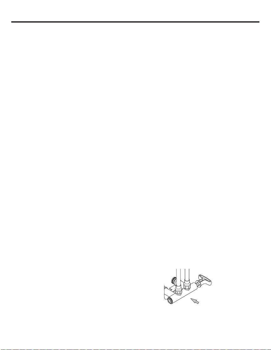
7. Check for leaks around clips at softener’s
inlet and outlet. If a leak occurs at a clip,
depressurize the plumbing (turn off the water
supply and open faucets) before removing
clip. When removing clips at the softener’s
inlet or outlet, push the single bypass valve
body toward the softener (See Figure 12).
Improper removal may damage clips. Do not
reinstall damaged clips.
....depressurize the
plumbing, then push
Bypass Valve body
toward softener
If removing
clips.....
Figure 12
Installation Instructions
Loading ...
Loading ...
Loading ...