Loading ...
Loading ...
Loading ...
Black plate (44,1)
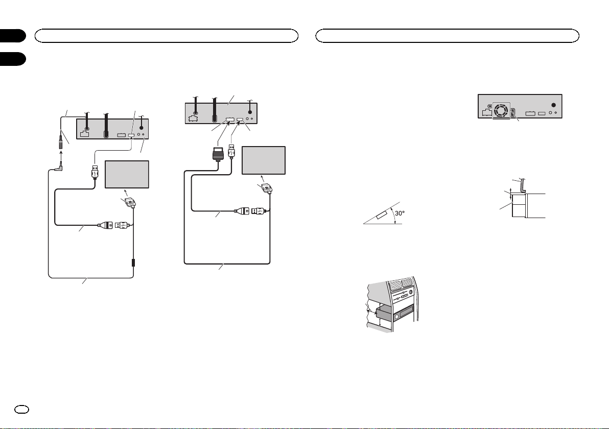
iPod with 30-pin connector
When connecting with optional
CD-IU201V cable
This product
Interface cable
(CD-IU201V) (sold separately)
AUX input (AUX IN)
1.5 m (4 ft. 11 in.)
Dock connector
USB cable
(Supplied with this unit)
Connect to separately sold
USB device.
USB/iPod input
iPod with video
capabilities
(sold separately)
17 cm (6-3/4 in.)
When connecting with optional
CD-IU201S cable
This product
1.5 m (4 ft. 11 in.)
Dock connector
USB cable
(Supplied with this unit)
Connect to separately sold
USB device.
USB/iPod input
iPod with video
capabilities
(sold separately)
RGB input
Interface cable
(CD-IU201S) (sold separately)
Notes
! Check all connections and systems before
final installation.
! Do not use unauthorized parts as this may
cause malfunctions.
! Consult your dealer if installation requires
drilling of holes or other modifications to the
vehicle.
! Do not install this unit where:
— it may interfere with operation of the vehicle.
— it may cause injury to a passenger as a result
of a sudden stop.
! The semiconductor laser will be damaged if
it overheats. Install this unit away from hot
places such as near the heater outlet.
! Optimum performance is obtained when the
unit is installed at an angle of less than 30°.
! When installing, to ensure proper heat dis-
persal when using this unit, make sure you
leave ample space behind the rear panel and
wrap any loose cables so they are not block-
ing the vents.
5cmcm
Leave ample
space
5 cm
5 cm
! The cords must not cover up the area shown
in the figure below. This is necessary to allow
the amplifiers to radiate freely.
1
1 Do not cover this area.
! Make sure you leave enough gap between
the dashboard and the LCD panel of this unit
so the LCD panel can be opened and closed
without contacting with the dashboard.
1
2
3
1 Dashboard
2 Leave gap
3 LCD panel
DIN front/rear-mount
This unit can be properly installed using either
front-mount or rear-mount installation.
Use commercially available parts when instal-
ling.
DIN Front-mount
1 Decide the position of the side brackets.
When installing in a shallow space, change the
position of side brackets (small).
Connection
44
Section
Installation
En
23
24
<CRD4711-C>44
Loading ...
Loading ...
Loading ...