READ IT OR WATCH IT
Read instructions or watch easy-to-follow video.
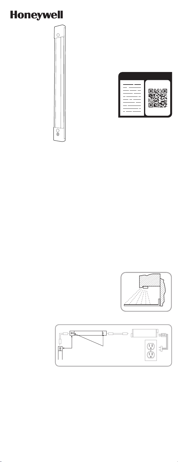
Scan QR code or visit http://bit.ly/2KBGCt9
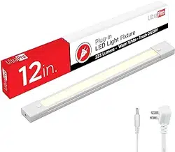
44404 (1 PACK), 44405 (2 PACK), 44406 (3 PACK)
PLUG-IN
LED LIGHT FIXTURE
SAVE THESE INSTRUCTIONS FOR POSSIBLE FUTURE USE.
CAUTION: DO NOT USE POWER TOOLS TO SECURE SCREWS, AS
THERE IS A RISK OF STRIPPING THE SCREWS.
DO NOT USE WITH A DIMMER OR DIMMING CIRCUIT.
IF LINKING MULTIPLE LIGHT FIXTURES, ADD WATTAGE OF EACH,
MAKING SURE NOT TO EXCEED THE MAXIMUM WATTAGE OUTPUT OF
THE LED DRIVER.
IMPORTANT SAFETY INSTRUCTIONS
The LED light fixture has a polarized plug (one blade is wider than the other) to reduce the risk of
electric shock. This plug fits in a polarized outlet only one way. If the plug does not fit fully in the
outlet, reverse the plug. If it still does not fit, contact a qualified electrician. Do not alter the plug.
Read entire installation instructions before you begin.
INSTALLATION PROCEDURE FOR PLUGIN LIGHT FIXTURE
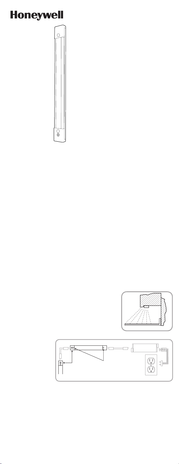
Carefully plan your installation prior to mounting the LED light
fixture. For kitchen installations, the recommended mounting
for the LED light fixture is under the cabinets near the front lip,
as shown in Figure 1. This provides the best light distribution
across a countertop. Make sure that the power supply cord will
reach the nearest electrical outlet, and that the power adapter
and the USBC cord will reach the LED light fixture. See Figure 2
for layout of components and all electrical connections.
1. DO NOT ATTEMPT TO INSTALL LED LIGHT FIXTURE WHILE PLUGGED IN.
2. Select a suitable dry mounting location (for use indoors only). Make sure mounting
surface is capable of supporting the LED light fixture and power adapter/LED driver.
3. Remove the two rubber plugs from the LED light fixture to reveal the screw mounting
holes.
4. Locate position where the LED light fixture and power adapter will be mounted.
5. While holding the LED light fixture in the desired location, clearly mark the location of
the mounting holes.
6. Pre-drill holes in the mounting surface with a 1/16” (1.5mm) drill bit at the marked
mounting hole locations.
7. Place the provided 1/2” wood screws in the mounting holes of the LED light fixture
and drive the two screws into the pre-drilled holes in the mounting surface. Use only a
#1 Phillips head manual screwdriver to avoid stripping the screws.
8. Reinsert the two rubber plugs into the mounting holes.
This device complies with Part 15 of the FCC and Industry Canada license-exempt RSS
standards. Operation is subject to the following two conditions: (1) this device may not cause
harmful interference, and (2) this device must accept any interference received, including
interference that may cause undesired operation.
FCC NOTE: The manufacturer is not responsible for any radio or TV interference caused by
unauthorized modifications to this equipment. Such modifications could void the user’s
authority to operate the equipment.
NOTE: This equipment has been tested and found to comply with the limits for a Class B
digital device, pursuant to Part 15 of the FCC Rules. These limits are designed to provide
reasonable protection against harmful interference in a residential installation. This
equipment generates, uses and can radiate radio frequency energy, and if not installed
and used in accordance with the instructions, may cause harmful interference to radio
communications. However, there is no guarantee interference will not occur in a particular
installation. If this equipment does cause harmful interference to radio or television
reception, which can be determined by turning the equipment off and on, the user is
encouraged to try to correct the interference by one or more of the following measures:
— Reorient or relocate the receiving antenna.
— Increase the separation between the equipment and receiver.
— Connect the equipment into an outlet on a circuit different from which the receiver
is connected.
— Consult the dealer or an experienced radio/TV technician for help.
CAN ICES3(B)/NMB3(B)
Questions? Contact our U.S.-based Consumer Care at 18556988324,
MondayFriday, 7AM8PM CST.
For the most up-to-date product support, accessories, electronic (PDF) format manuals and
more, visit www.byjasco.com/support.
DO NOT RETURN THIS
PRODUCT TO THE STORE
STOP
FCC/IC - EN
SPECIFICATIONS
The Honeywell trademark is used under license from Honeywell International Inc.
Honeywell International Inc. makes no representation or warranties with respect to this product.
This product is manufactured by Jasco Products Company LLC.
This Jasco product comes with a limited-lifetime warranty. Visit www.byjasco.com for warranty details.
MADE IN CHINA/HECHO EN CHINA
©JASCO 2019 | 44404, 44405, 44406 | 08/07/19 v1
Jasco Products Company LLC.
10 E. Memorial Road
Oklahoma City, OK 73114
120VAC 60Hz
5W
233 Lumens
93 CRI
2700K CCT White
120VAC 60Hz
10W
466 Lumens
93 CRI
2700K CCT White
120VAC 60Hz
15W
699 Lumens
93 CRI
2700K CCT White
44404 (1 PACK) 44405 (2 PACK) 44406 (3 PACK)
FIGURE 2
FIGURE 1
CABINET
COUNTER TOP
WALL
3 Pin
18” linking cord
Power Adapter
LED Light Fixture
ON/OFF
touch sensor
18” linking
cord
rubber plugs/
mounting holes
DO NOT exceed maximum units as indicated on power adapter.
9. Repeat steps 1 through 8 for additional LED light fixtures, making sure they are within
18” of each other so that they can be connected by the provided 18” linking cord.
Note: DO NOT connect more than the maximum units indicated on the power
adapter/LED driver.
10. Use the provided 18” linking cords to connect the LED light fixtures together by
inserting the male end of the linking cord into the corresponding female connection
point on each LED light fixture.
MOUNTING THE POWER ADAPTER AND OPERATION OF LED LIGHT
FIXTURES
FIGURE 3
11. The LED light fixture comes with an in-line power
adapter/LED driver. To mount power adapter, place
adapter in desired location and mark in the round
portion of the mounting tabs, as shown in Figure 3.
12. Pre-drill holes in the mounting surface with a 1/16”
(1.5mm) drill bit at the marked mounting hole
locations.
13. Drive the provided 5/8” wood screws into the
mounting surface until approximately 1/16” (1.5mm)
of space remains under the head of the screw.
14. Place the power adapter onto the screws and slide to either side to secure into place. If
necessary, tighten screws to secure in place.
15. Use the provided 18” linking cord to connect the power adapter to the LED light
fixture by placing the male end of the linking cord into the corresponding female
connection point on the power adapter and LED light fixture. See Figure 2.
16. Plug the 3-pin connector of the power supply cord into the corresponding connection
point on the power adapter. See Figure 2.
17. Plug the power supply cord into any 120VAC/60Hz outlet. See Figure 2.
18. The connected LED light fixtures turn on/off by touching the on/off touch sensor on
each fixture as shown in Figure 2. Note: Each LED light fixture will turn on/off
independently of other connected LED light fixtures.
INSTALLATION INSTRUCTIONS FOR ATTACHING ADDITIONAL LED
LIGHT FIXTURES AT A LATER DATE
If you desire additional LED light fixtures for your system after the initial installation, you may
attach them as needed (sold separately) by following these instructions. Keep in mind the
maximum linking distance between fixtures is 18". If linking multiple light fixtures, add wattage
of each, making sure not to exceed the maximum wattage output of the LED driver.
CAUTION: DO NOT ATTEMPT TO ATTACH ADDITIONAL LED LIGHT FIXTURES TO YOUR
EXISTING SYSTEM WITHOUT UNPLUGGING THE LINE CORD FROM THE ELECTRICAL
OUTLET OR DISCONNECTING THE ELECTRICITY AT THE ELECTRICAL POWER PANEL.
A. Install additional LED light fixtures following steps 18 of the installation instructions.
B. Once installed, attach the 18” cord between the last LED light fixture (previously installed)
and the new one. See Figure 2 to for layout of components and all electrical connections.
C. When adding LED light fixtures to an existing system of linked light bars, the line cord (with
the power plug) and power adapter are not needed. Only the first light fixture in the chain
needs to be connected to power adapter with the line cord.
RISK OF ELECTRICAL SHOCK
• DO NOT USE IN WET LOCATIONS
• USE INDOORS ONLY
• USE ONLY INSULATED STAPLES OR
PLASTIC TIES TO SECURE THE CORDS
• ROUTE AND SECURE THE CORDS SO
THAT THEY WILL NOT BE PINCHED OR
DAMAGED
NO SERVICEABLE PARTS
NONREPLACEABLE LEDS
LED LIGHT OUTPUT IS STRONG
ENOUGH TO INJURE HUMAN EYES.
PRECAUTIONS MUST BE TAKEN TO
PREVENT LOOKING DIRECTLY AT THE
LEDS WITH UNAIDED EYES FOR MORE
THAN A FEW SECONDS
RISK OF FIRE
• NOT INTENDED FOR ILLUMINATION OF
AQUARIUMS
• NOT INTENDED FOR USE ABOVE
STOVES, COOK TOPS, SINKS OR OTHER
HEAT PRODUCING APPLIANCES, SUCH
AS COFFEE MAKERS, TOASTERS, OR
TOASTER OVENS
• NOT INTENDED FOR RECESSED
INSTALLATION IN CEILINGS OR
SOFFITS
• NOT INTENDED FOR SURFACE
INSTALLATION INSIDE OR ON TOP
OF BUILTIN FURNISHINGS SUCH AS
KITCHEN CABINETS, CHINA CABINETS,
OR TROPHY CASES
• DO NOT CONCEAL POWER SUPPLY
CORD OR LINKING CORDS INSIDE
A WALL, CEILING, SOFFIT, KITCHEN
CABINET, OR SIMILAR PERMANENT
STRUCTURE
• DO NOT RUN THE POWER SUPPLY
CORD OR LINKING CORDS THROUGH
HOLES IN WALLS, CEILINGS OR
FLOORS
WARNING

READ IT OR WATCH IT
Read instructions or watch easy-to-follow video.
Scan QR code or visit http://bit.ly/2KBGCt9
44404 (1 PACK), 44405 (2 PACK), 44406 (3 PACK)
PLUG-IN
LED LIGHT FIXTURE
SAVE THESE INSTRUCTIONS FOR POSSIBLE FUTURE USE.
CAUTION: DO NOT USE POWER TOOLS TO SECURE SCREWS, AS
THERE IS A RISK OF STRIPPING THE SCREWS.
DO NOT USE WITH A DIMMER OR DIMMING CIRCUIT.
IF LINKING MULTIPLE LIGHT FIXTURES, ADD WATTAGE OF EACH,
MAKING SURE NOT TO EXCEED THE MAXIMUM WATTAGE OUTPUT OF
THE LED DRIVER.
IMPORTANT SAFETY INSTRUCTIONS
The LED light fixture has a polarized plug (one blade is wider than the other) to reduce the risk of
electric shock. This plug fits in a polarized outlet only one way. If the plug does not fit fully in the
outlet, reverse the plug. If it still does not fit, contact a qualified electrician. Do not alter the plug.
Read entire installation instructions before you begin.
INSTALLATION PROCEDURE FOR PLUGIN LIGHT FIXTURE
Carefully plan your installation prior to mounting the LED light
fixture. For kitchen installations, the recommended mounting
for the LED light fixture is under the cabinets near the front lip,
as shown in Figure 1. This provides the best light distribution
across a countertop. Make sure that the power supply cord will
reach the nearest electrical outlet, and that the power adapter
and the USBC cord will reach the LED light fixture. See Figure 2
for layout of components and all electrical connections.
1. DO NOT ATTEMPT TO INSTALL LED LIGHT FIXTURE WHILE PLUGGED IN.
2. Select a suitable dry mounting location (for use indoors only). Make sure mounting
surface is capable of supporting the LED light fixture and power adapter/LED driver.
3. Remove the two rubber plugs from the LED light fixture to reveal the screw mounting
holes.
4. Locate position where the LED light fixture and power adapter will be mounted.
5. While holding the LED light fixture in the desired location, clearly mark the location of
the mounting holes.
6. Pre-drill holes in the mounting surface with a 1/16” (1.5mm) drill bit at the marked
mounting hole locations.
7. Place the provided 1/2” wood screws in the mounting holes of the LED light fixture
and drive the two screws into the pre-drilled holes in the mounting surface. Use only a
#1 Phillips head manual screwdriver to avoid stripping the screws.
8. Reinsert the two rubber plugs into the mounting holes.
This device complies with Part 15 of the FCC and Industry Canada license-exempt RSS
standards. Operation is subject to the following two conditions: (1) this device may not cause
harmful interference, and (2) this device must accept any interference received, including
interference that may cause undesired operation.
FCC NOTE: The manufacturer is not responsible for any radio or TV interference caused by
unauthorized modifications to this equipment. Such modifications could void the user’s
authority to operate the equipment.
NOTE: This equipment has been tested and found to comply with the limits for a Class B
digital device, pursuant to Part 15 of the FCC Rules. These limits are designed to provide
reasonable protection against harmful interference in a residential installation. This
equipment generates, uses and can radiate radio frequency energy, and if not installed
and used in accordance with the instructions, may cause harmful interference to radio
communications. However, there is no guarantee interference will not occur in a particular
installation. If this equipment does cause harmful interference to radio or television
reception, which can be determined by turning the equipment off and on, the user is
encouraged to try to correct the interference by one or more of the following measures:
— Reorient or relocate the receiving antenna.
— Increase the separation between the equipment and receiver.
— Connect the equipment into an outlet on a circuit different from which the receiver
is connected.
— Consult the dealer or an experienced radio/TV technician for help.
CAN ICES3(B)/NMB3(B)
Questions? Contact our U.S.-based Consumer Care at 18556988324,
MondayFriday, 7AM8PM CST.
For the most up-to-date product support, accessories, electronic (PDF) format manuals and
more, visit www.byjasco.com/support.
DO NOT RETURN THIS
PRODUCT TO THE STORE
STOP
FCC/IC - EN
SPECIFICATIONS
The Honeywell trademark is used under license from Honeywell International Inc.
Honeywell International Inc. makes no representation or warranties with respect to this product.
This product is manufactured by Jasco Products Company LLC.
This Jasco product comes with a limited-lifetime warranty. Visit www.byjasco.com for warranty details.
MADE IN CHINA/HECHO EN CHINA
©JASCO 2019 | 44404, 44405, 44406 | 08/07/19 v1
Jasco Products Company LLC.
10 E. Memorial Road
Oklahoma City, OK 73114
120VAC 60Hz
5W
233 Lumens
93 CRI
2700K CCT White
120VAC 60Hz
10W
466 Lumens
93 CRI
2700K CCT White
120VAC 60Hz
15W
699 Lumens
93 CRI
2700K CCT White
44404 (1 PACK) 44405 (2 PACK) 44406 (3 PACK)
FIGURE 2
FIGURE 1
CABINET
COUNTER TOP
WALL
3 Pin
18” linking cord
Power Adapter
LED Light Fixture
ON/OFF
touch sensor
18” linking
cord
rubber plugs/
mounting holes
DO NOT exceed maximum units as indicated on power adapter.
9. Repeat steps 1 through 8 for additional LED light fixtures, making sure they are within
18” of each other so that they can be connected by the provided 18” linking cord.
Note: DO NOT connect more than the maximum units indicated on the power
adapter/LED driver.
10. Use the provided 18” linking cords to connect the LED light fixtures together by
inserting the male end of the linking cord into the corresponding female connection
point on each LED light fixture.
MOUNTING THE POWER ADAPTER AND OPERATION OF LED LIGHT
FIXTURES
FIGURE 3
11. The LED light fixture comes with an in-line power
adapter/LED driver. To mount power adapter, place
adapter in desired location and mark in the round
portion of the mounting tabs, as shown in Figure 3.
12. Pre-drill holes in the mounting surface with a 1/16”
(1.5mm) drill bit at the marked mounting hole
locations.
13. Drive the provided 5/8” wood screws into the
mounting surface until approximately 1/16” (1.5mm)
of space remains under the head of the screw.
14. Place the power adapter onto the screws and slide to either side to secure into place. If
necessary, tighten screws to secure in place.
15. Use the provided 18” linking cord to connect the power adapter to the LED light
fixture by placing the male end of the linking cord into the corresponding female
connection point on the power adapter and LED light fixture. See Figure 2.
16. Plug the 3-pin connector of the power supply cord into the corresponding connection
point on the power adapter. See Figure 2.
17. Plug the power supply cord into any 120VAC/60Hz outlet. See Figure 2.
18. The connected LED light fixtures turn on/off by touching the on/off touch sensor on
each fixture as shown in Figure 2. Note: Each LED light fixture will turn on/off
independently of other connected LED light fixtures.
INSTALLATION INSTRUCTIONS FOR ATTACHING ADDITIONAL LED
LIGHT FIXTURES AT A LATER DATE
If you desire additional LED light fixtures for your system after the initial installation, you may
attach them as needed (sold separately) by following these instructions. Keep in mind the
maximum linking distance between fixtures is 18". If linking multiple light fixtures, add wattage
of each, making sure not to exceed the maximum wattage output of the LED driver.
CAUTION: DO NOT ATTEMPT TO ATTACH ADDITIONAL LED LIGHT FIXTURES TO YOUR
EXISTING SYSTEM WITHOUT UNPLUGGING THE LINE CORD FROM THE ELECTRICAL
OUTLET OR DISCONNECTING THE ELECTRICITY AT THE ELECTRICAL POWER PANEL.
A. Install additional LED light fixtures following steps 18 of the installation instructions.
B. Once installed, attach the 18” cord between the last LED light fixture (previously installed)
and the new one. See Figure 2 to for layout of components and all electrical connections.
C. When adding LED light fixtures to an existing system of linked light bars, the line cord (with
the power plug) and power adapter are not needed. Only the first light fixture in the chain
needs to be connected to power adapter with the line cord.
RISK OF ELECTRICAL SHOCK
• DO NOT USE IN WET LOCATIONS
• USE INDOORS ONLY
• USE ONLY INSULATED STAPLES OR
PLASTIC TIES TO SECURE THE CORDS
• ROUTE AND SECURE THE CORDS SO
THAT THEY WILL NOT BE PINCHED OR
DAMAGED
NO SERVICEABLE PARTS
NONREPLACEABLE LEDS
LED LIGHT OUTPUT IS STRONG
ENOUGH TO INJURE HUMAN EYES.
PRECAUTIONS MUST BE TAKEN TO
PREVENT LOOKING DIRECTLY AT THE
LEDS WITH UNAIDED EYES FOR MORE
THAN A FEW SECONDS
RISK OF FIRE
• NOT INTENDED FOR ILLUMINATION OF
AQUARIUMS
• NOT INTENDED FOR USE ABOVE
STOVES, COOK TOPS, SINKS OR OTHER
HEAT PRODUCING APPLIANCES, SUCH
AS COFFEE MAKERS, TOASTERS, OR
TOASTER OVENS
• NOT INTENDED FOR RECESSED
INSTALLATION IN CEILINGS OR
SOFFITS
• NOT INTENDED FOR SURFACE
INSTALLATION INSIDE OR ON TOP
OF BUILTIN FURNISHINGS SUCH AS
KITCHEN CABINETS, CHINA CABINETS,
OR TROPHY CASES
• DO NOT CONCEAL POWER SUPPLY
CORD OR LINKING CORDS INSIDE
A WALL, CEILING, SOFFIT, KITCHEN
CABINET, OR SIMILAR PERMANENT
STRUCTURE
• DO NOT RUN THE POWER SUPPLY
CORD OR LINKING CORDS THROUGH
HOLES IN WALLS, CEILINGS OR
FLOORS
WARNING
44404 (PACK DE 1 UNIDAD), 44405 (PACK DE 2
UNIDADES), 44406 (PACK DE 3 UNIDADES)
ACCESORIO DE LUZ LED ENCHUFABLE
GUARDE LAS SIGUIENTES INSTRUCCIONES PARA UN POSIBLE USO
EN EL FUTURO.
PRECAUCIÓN: NO USE HERRAMIENTAS ELÉCTRICAS PARA FIJAR LOS
TORNILLOS, YA QUE EXISTE EL RIESGO DE BARRERLOS.
NO USE CON ATENUADORES NI CIRCUITOS ATENUADORES.
SI VA A COLOCAR VARIOS APLIQUES DE LUZ, SUME LA POTENCIA DE
CADA UNO Y ASEGÚRESE DE NO SUPERAR LA POTENCIA MÁXIMA
DEL CONTROLADOR LED.
INSTRUCCIONES DE SEGURIDAD IMPORTANTES
Este aparato de luz LED tiene un enchufe polarizado (es decir una clavija del enchufe es
más ancha que la otra) para reducir el riesgo de descarga eléctrica. Este enchufe encaja
solo de una manera en un tomacorriente polarizado. Si el enchufe no encaja por completo
en el tomacorriente, inviértalo. Si aun así no encaja, llame a un electricista profesional.
No modifique el enchufe. Antes de comenzar, lea todas las instrucciones de instalación.
PROCEDIMIENTO DE INSTALACIÓN DEL ACCESORIO DE LUZ
LED ENCHUFABLE
Planifique detenidamente la instalación antes de montar
el accesorio de luz LED. Para instalaciones en cocinas, se
recomienda que el accesorio de luz LED se instale debajo
de los gabinetes cerca del borde frontal, como se muestra
en la Figura 1. De esta manera, logrará la mejor distribución
de luz en toda la encimera. Asegúrese de que el cable de
alimentación llegue al tomacorriente más cercano y de que el
adaptador de corriente y el cable USB-C lleguen al accesorio
de luz LED. Consulte la Figura 2 para ver la distribución de los
componentes y de todas las conexiones eléctricas.
1. NO INTENTE INSTALAR EL ACCESORIO DE LUZ LED SI ESTÁ ENCHUFADO.
2. Seleccione un lugar seco adecuado para la instalación (para uso en interiores
únicamente). Asegúrese de que la superficie en la que desea instalar el accesorio de luz
LED y el adaptador de corriente/controlador de LED podrá soportar el peso.
3. Quite los dos tapones de goma del accesorio de luz LED para ver los orificios de los
tornillos de instalación.
4. Ubique los lugares donde se instalarán el accesorio de luz LED y el adaptador de
corriente.
5. Mientras sostiene el accesorio de luz LED en la posición deseada, marque claramente la
ubicación de los orificios de instalación.
6. Perfore los orificios en la superficie de instalación con una broca de 1/16in. (1,5 mm) en
los sitios especificados de los orificios de montaje.
7. Coloque los tornillos para madera de 1/2in. provistos en los orificios de instalación
del accesorio de luz LED y atorníllelos en los orificios ya perforados en la superficie de
montaje. Use únicamente un destornillador manual Phillips número 1 así evitará barrer
los tornillos.
Este dispositivo cumple con las especificaciones del apartado 15 de las normas de la FCC
y con las especificaciones de las normas radioeléctricas (RSS) del Ministerio de Industria
de Canadá aplicables a aparatos exentos de licencia. El funcionamiento está sujeto a las
siguientes dos condiciones: (1) este dispositivo no debe provocar interferencia perjudicial, y
(2) este dispositivo debe aceptar toda interferencia que reciba, incluso la que pudiera causar
un funcionamiento no deseado.
NOTA DE LA FCC: El fabricante no se hace responsable de ninguna interferencia de radio
o TV ocasionada por modificaciones no autorizadas efectuadas a este dispositivo. Dichas
modificaciones podrían anular la autoridad del usuario para utilizar este dispositivo.
NOTA: Este equipo ha sido probado y cumple con los límites para aparatos digitales
de Clase B, de conformidad con el apartado 15 de la normativa de la FCC. Estos límites
están diseñados para proveer protección razonable contra interferencias perjudiciales
en instalaciones residenciales. Este dispositivo genera, usa y puede irradiar energía
de radiofrecuencias y, si no se instala y usa según las instrucciones, puede provocar
interferencia perjudicial a las radiocomunicaciones. No obstante, no hay garantías de que
no ocurrirá interferencia en una instalación en particular. Si este equipo genera alguna
interferencia perjudicial a la recepción de radio o televisión, lo que puede determinarse
encendiendo y apagando el equipo, se recomienda que el usuario intente corregir la
interferencia aplicando una o más de las siguientes medidas:
— Reoriente o reubique la antena receptora.
— Incremente la separación entre el equipo y el receptor.
— Conecte el dispositivo a un tomacorriente de un circuito diferente del circuito al que el
receptor está conectado.
— Consulte al distribuidor o a un técnico con experiencia en radio/televisión para solicitar
asistencia.
CAN ICES-3(B)/NMB-3(B)
¿Preguntas? Comuníquese con nuestro Centro de atención al cliente con sede en EE. UU. al
1-855-698-8324, de lunes a viernes, de 7:00 a. m. a 8:00 p. m. CST (hora central estándar).
Para recibir el soporte técnico más actualizado sobre productos, accesorios, manuales en
formato digital (PDF), entre otros, visite www.byjasco.com/support
NO DEVUELVA ESTE
PRODUCTO A LA TIENDA
¡DETÉNGASE!
FCC/IC - ESP
ESPECIFICACIONES
120 VCA 60 Hz
5 W
233 lúmenes
93 CRI
Blanca CCT 2700 K
120 VCA 60 Hz
10 W
466 lúmenes
93 CRI
Blanca CCT 2700 K
120 VCA 60 Hz
15 W
699 lúmenes
93 CRI
Blanca CCT 2700 K
44404
(PACK DE 1 UNIDAD)
44405
(PACK DE 2 UNIDADES)
44406
(PACK DE 3 UNIDADES)
FIGURA 2
FIGURA 1
GABINETE
ENCIMERA
PARED
3 clavijas
Cable de conexión
de 18"
Adaptador
de corriente
Accesorio de luz LED
Sensor táctil de
ENCENDIDO/APAGADO
(ON/OFF)
Cable de conexión de 18"
Tapones de goma/orificios
de instalación
NO EXCEDA el máximo de unidades que se indica en el adaptador de corriente.
8. Reinserte los dos tapones de goma en los orificios de instalación.
9. Repita los pasos 1 a 8 para accesorios de luz LED adicionales, asegurándose de que
estén a no más de 18in. uno del otro para que puedan conectarse con el cable de
conexión de 18in. provisto.
Nota: NO conecte más del máximo de unidades que se indica en el adaptador de
corriente/controlador de LED.
10. Use los cables de conexión de 18in. provistos para conectar los accesorios de luz LED
juntos al insertar el extremo macho del cable de conexión en el punto de conexión
hembra correspondiente en cada accesorio de luz LED.
FIGURA 3
INSTALACIÓN DEL ADAPTADOR DE CORRIENTE Y FUNCIONAMIENTO
DE LOS ACCESORIOS DE LUZ LED
11. El accesorio de luz LED cuenta con un adaptador de
corriente en línea/controlador de LED. Para instalar el
adaptador de corriente, coloque el adaptador en el lugar
indicado y marque el área circular de las presillas de
instalación como se muestra en la Figura 3.
12. Perfore los orificios en la superficie de instalación con una
broca de 1/16in. (1,5 mm) en los sitios especificados de los
orificios de montaje.
13. Inserte los tornillos provistos para madera de 5/8" en
la superficie de montaje hasta que quede un espacio
aproximado de 1/16in. (1,5 mm) entre la superficie y la
cabeza del tornillo.
14. Coloque el adaptador de corriente sobre los tornillos y deslícelo hacia cualquiera de los
lados para fijarlo firmemente. De ser necesario ajuste los tornillos para asegurarlo.
15. Use el cable de conexión de 18in. provisto para conectar el adaptador de corriente al
accesorio de luz LED al colocar el extremo macho del cable de conexión en el punto de
conexión hembra correspondiente del adaptador de corriente y del accesorio de luz LED.
Ver Figura 2.
16. Enchufe el conector de 3 clavijas del cable de alimentación en el punto de conexión
correspondiente del adaptador de corriente. Ver Figura 2.
17. Enchufe el cable de alimentación a un tomacorriente de 120 VCA 60 Hz. Ver Figura 2.
18. Los accesorios de luz LED conectados se encenderán o apagarán (on/off) al tocar el
sensor táctil de encendido o apagado en cada accesorio como se muestra en la Figura 2.
Nota: Cada accesorio de luz LED se encenderá o apagará de forma independiente de los
demás accesorios de luz LED conectados.
INSTRUCCIONES DE INSTALACIÓN PARA CONECTAR OTROS
ACCESORIOS DE LUZ LED EN OTRO MOMENTO
Si después de la instalación inicial, desea agregar más accesorios de luz LED al sistema de
iluminación, podrá hacerlo según sea necesario (se venden por separado) siguiendo estas
instrucciones. Tenga presente que la distancia máxima de conexión entre accesorios es de
18in. Si va a colocar varios apliques de luz, sume la potencia de cada uno y asegúrese de no
superar la potencia máxima del controlador LED.
PRECAUCIÓN: NO INTENTE INSTALAR OTROS ACCESORIOS DE LUZ LED EN EL SISTEMA
EXISTENTE SIN HABER DESENCHUFADO EL CABLE DE LÍNEA DEL TOMACORRIENTE O
DESCONECTADO EL SUMINISTRO DE ENERGÍA EN EL TABLERO ELÉCTRICO.
A. Instale los accesorios de luz LED adicionales siguiendo los pasos 1 a 8 de las
instrucciones de instalación.
B. Una vez instalados, conecte el cable de 18in. entre el último accesorio de luz LED
(previamente instalado) y el nuevo. Consulte la Figura 2 para ver la distribución de los
componentes y de todas las conexiones eléctricas.
C. Cuando agrega accesorios de luz LED a un sistema existente de barras de luces ya
conectadas entre sí, no es necesario tener cables de línea (con enchufe de alimentación)
ni adaptadores de corriente. Solo el primer accesorio de luz en la cadena de aparatos
tiene que estar conectado al adaptador de corriente con el cable de línea.
RIESGO DE DESCARGA ELÉCTRICA
• NO UTILICE EN LUGARES HÚMEDOS
• SOLO PARA USO EN INTERIORES
• PARA FIJAR LOS CABLES, SOLO USE
GRAPAS AISLADAS O PRECINTOS
DE PLÁSTICO.
• PASE Y FIJE LOS CABLES DE MODO
QUE NO QUEDEN APRETADOS NI
SE DAÑEN
NO TIENE PIEZAS QUE EL USUARIO
PUEDA REPARAR.
LUCES LED NO REEMPLAZABLES.
EL BRILLO DE LA LUZ LED ES TAN
FUERTE QUE PUEDE DAÑAR LOS
OJOS HUMANOS.
TOME PRECAUCIONES PARA NO MIRAR
DIRECTAMENTE A LAS LUCES LED CON
LOS OJOS DESCUBIERTOS POR MÁS DE
UNOS SEGUNDOS.
RIESGO DE INCENDIO
• ESTA UNIDAD NO ESTÁ DISEÑADA PARA
LA ILUMINACIÓN DE PECERAS
• NO SE DEBE USAR SOBRE HORNILLOS,
PLACAS DE COCINA, FREGADEROS
NI NINGÚN OTRO DISPOSITIVO QUE
GENERE CALOR, COMO CAFETERAS,
TOSTADORAS NI HORNOS ELÉCTRICOS
• ESTA UNIDAD NO ESTÁ DISEÑADA PARA
MONTAJE EMPOTRADO AL TECHO O
EN UN SOFITO
• ESTA UNIDAD NO ESTÁ DISEÑADA
PARA INSTALARSE EN EL INTERIOR NI
ENCIMA DE MUEBLES EMPOTRADOS,
COMO MUEBLES DE COCINA O
VITRINAS
• NO OCULTE EL CABLE DE
ALIMENTACIÓN ELÉCTRICA O LOS
CABLES DE CONEXIÓN DENTRO
DE UNA PARED, EL CIELO RASO, UN
SOFITO, UN MUEBLE DE COCINA
O UNA ESTRUCTURA SIMILAR QUE
SEA PERMANENTE
• NO PASE EL CABLE DE ALIMENTACIÓN
ELÉCTRICA NI LOS CABLES DE
CONEXIÓN POR ORIFICIOS EN
PAREDES, EL CIELO RASO O EL SUELO
ADVERTENCIA